9. Configuring the LAN Interface(s)
9.1. Basic Settings
LAN interface settings are located at Network > LAN > Network Settings. Navigating to that page will show the following dashboard:

This represents the LAN interfaces that are active on your router (including VLAN). A gray “X” means that the VLAN is used in other settings and cannot be deleted. You can find which settings are using the VLAN by hovering over the gray “X”.
Alternatively, a red “X” means that there are no settings using the VLAN. You can delete that VLAN by clicking the red “X”.
Note: Default VLAN 1 is used for untagged LAN. Unused VLAN will be assigned if user has configured VLAN 1 for some other LAN network in previous firmware version.
Clicking on any of the existing LAN interfaces (or creating a new one) will show the following:

IP Settings | |
IP Address | The IP address and subnet mask of the Peplink router on the LAN. |

Network Settings | |
Name | Enter a name for the LAN. |
VLAN ID | Enter a number for your VLAN. |
Inter-VLAN routing | Check this box to enable routing between virtual LANs. |
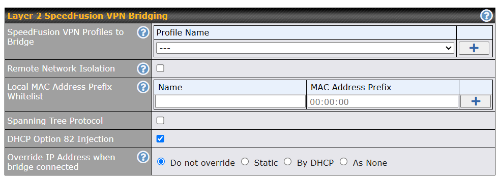
Layer 2 SpeedFusion VPN Bridging | |
SpeedFusion VPN Profiles to Bridge | The remote network of the selected SpeedFusion VPN profiles will be bridged with this local LAN, creating a Layer 2 SpeedFusion VPN, they will be connected and operate like a single LAN, and any broadcast or multicast packets will be sent over the VPN. |
Remote Network Isolation | Enable this option if you want to block network traffic between the remote networks, this will not affect the connectivity between them and this local LAN. |
Local MAC Address Prefix | This feature filters packets with unicast MAC addresses and applies to packets between local networks and the Layer 2 tunnel. Packets forwarded from one Layer 2 tunnel to another will not be filtered. When the list is empty, the feature will be disabled. If MAC addresses are defined in the list, only packets to and from these addresses will be allowed through the Layer 2 tunnel. MAC Address allows input as a prefix, e.g. 10:56:CA will whitelist 10:56:CA:00:00:00 to 10:56:CA:FF:FF:FF. |
Spanning Tree Protocol | Clicking the box will enable STP for this layer 2 profile bridge. |
DHCP Option 82 | Click on the question mark if you want to enable DHCP Option 82. This allows the device to inject Option 82 with Router Name information before forwarding the DHCP Request packet to a SpeedFusion VPN peer, such that the DHCP Server can identify where the request originates from. |
Override IP Address when bridge connected | Select "Do not override" if the LAN IP address and local DHCP server should remain unchanged after the Layer 2 SpeedFusion VPN is up. If you choose to override the IP address when the VPN is connected, the device will not act as a router, and most Layer 3 routing functions will cease to work. |
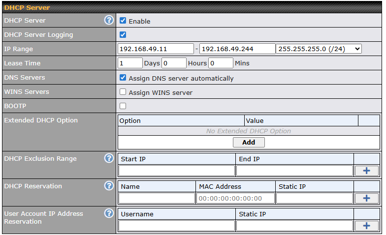
DHCP Server Settings | |
DHCP Server | When this setting is enabled, the Peplink router’s DHCP server automatically assigns an IP address to each computer that is connected via LAN and configured to obtain an IP address via DHCP. The Peplink router’s DHCP server can prevent IP address collisions on the LAN. To enable DHCP bridge relay, please click the |
DHCP Server Logging | Enable logging of DHCP events in the eventlog by selecting the checkbox. |
IP Range | These settings allocate a range of IP addresses that will be assigned to LAN computers by the Peplink router’s DHCP server. |
Lease Time | This setting specifies the length of time throughout which an IP address of a DHCP client remains valid. Upon expiration of Lease Time, the assigned IP address will no longer be valid and the IP address assignment must be renewed. |
DNS Servers | This option allows you to input the DNS server addresses to be offered to DHCP clients. If Assign DNS server automatically is selected, the Peplink router’s built-in DNS server address (i.e., LAN IP address) will be offered. |
BOOTP | Check this box to enable BOOTP on older networks that still require it. |
Extended DHCP Option | In addition to standard DHCP options (e.g. DNS server address, gateway address, subnet mask), you can specify the value of additional extended DHCP options, as defined in RFC 2132. With these extended options enabled, you can pass additional configuration information to LAN hosts. To define an extended DHCP option, click the Add button, choose the option to define, and then enter its value. For values that are in IP address list format, you can enter one IP address per line in the provided text area input control. Each option can be defined once only. |
DHCP Exclusion Range | To reserve a range of IP addresses from the DHCP pool, users may exclude a smaller range of IP addresses to avoid IP release behavior. Note: The start IP should be lower than the end IP, and both the start and end IPs should be within the range of the DHCP pool. |
DHCP Reservation | This setting reserves the assignment of fixed IP addresses for a list of computers on the LAN. The computers to be assigned fixed IP addresses on the LAN are identified by their MAC addresses. The fixed IP address assignment is displayed as a cross-reference list between the computers’ names, MAC addresses, and fixed IP addresses. Name (an optional field) allows you to specify a name to represent the device. MAC addresses should be in the format of 00:AA:BB:CC:DD:EE. Press |
User Account IP Address Reservation | This setting reserves the fixed IP addresses assignment for the list of Remote User Access accounts. |
 icon on this menu item.
 to create a new record. Press
 to remove a record. Reserved clients information can be imported from the Client List, located at
To configure DHCP relay, first click the  button found next to the DHCP Server option to display the settings.
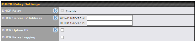
DHCP Relay Settings | |
Enable | Check this box to turn on DHCP relay. Click the |
DHCP Server IP Address | Enter the IP addresses of one or two DHCP servers in the provided fields. The DHCP servers entered here will receive relayed DHCP requests from the LAN. For active-passive DHCP server configurations, enter active and passive DHCP server relay IP addresses in DHCP Server 1 and DHCP Server 2. |
DHCP Option 82 | DHCP Option 82 includes device information as relay agent for the attached client when forwarding DHCP requests from client to server. This option also embeds the device’s MAC address and network name in circuit and remote IDs. Check this box to enable DHCP Option 82. |
DHCP Relay Logging | Enable logging of DHCP Relay events in the eventlog by selecting the checkbox. |
 icon to disable DHCP relay.
Once DHCP is set up, configure LAN Physical Settings, Static Route Settings, and DNS Proxy Settings as noted above.

Static Route Settings | |
Static Route | This table is for defining static routing rules for the LAN segment. A static route consists of the network address, subnet mask, and gateway address. The address and subnet mask values are in w.x.y.z format. Alternatively, static routes can be defined using a domain name and gateway address. The local LAN subnet and subnets behind the LAN will be advertised to the VPN. Remote routes sent over the VPN will also be accepted. Any VPN member will be able to route to the local subnet. Click Entries in this list will allow traffic to be routed to a different subnet that is connected to the LAN interface. Any traffic destined for a network/mask pair will be directed to the corresponding gateway instead of being routed through WANs. |


A - Advanced feature, please click the  button on the top right hand corner of the Static Route section to activate and configure Virtual Network Mapping to resolve network address conflict with remote peers.

In case of a network address conflict with remote peers (i.e. SpeedFusion VPN / IPsec VPN / IP Forwarding WAN are considered as remote connections), you can define Virtual Network Mapping to resolve it.
Note: OSPF & RIPv2 settings should be updated as well to avoid advertising conflicted networks.
For further details on virtual network mapping watch this video:
Virtual Network Mapping | |
One-to-One NAT | Every IP Address in the Local Network has a corresponding unique Virtual IP Address for NAT. |
Many-to-One NAT | The subnet range defined in Local Network will be mapped to a single Virtual IP Address for NAT. Traffic can only be initiated from local to remote, and this traffic will be NAT'ed and behave like coming from the same Virtual IP Address. |
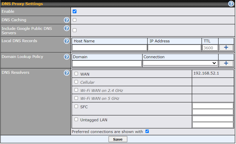
DNS Proxy Settings | |
Enable | To enable the DNS proxy feature, check this box, and then set up the feature at Network > LAN > DNS Proxy Settings. A DNS proxy server can be enabled to serve DNS requests originating from LAN/PPTP/SpeedFusionTM peers. Requests are forwarded to the DNS servers/resolvers defined for each WAN connection. |
DNS Caching | This field is to enable DNS caching on the built-in DNS proxy server. When the option is enabled, queried DNS replies will be cached until the records’ TTL has been reached. This feature can help improve DNS lookup time. However, it cannot return the most up-to-date result for those frequently updated DNS records. By default, DNS Caching is disabled. |
Include Google Public DNS Servers | When this option is enabled, the DNS proxy server will also forward DNS requests to Google's Public DNS Servers, in addition to the DNS servers defined in each WAN. This could increase the DNS service's availability. This setting is disabled by default. |
Local DNS Records | This table is for defining custom local DNS records. A static local DNS record consists of a host name and IP address. When looking up the host name from the LAN to LAN IP of the Peplink router, the corresponding IP address will be returned. Press |
Domain Lookup Policy | DNS Proxy will look up the domain names defined in this table using the specified connections only. |
DNS Resolvers A | This field specifies which DNS servers can receive forwarded DNS requests. If no DNS server is selected, then all of them will be selected by default. If you wish to select a SpeedFusion VPN peer, enter the IP address(es) of the VPN peer's DNS server. Incoming queries will be forwarded to one of the selected servers. If none of the selected servers can be reached, then the router will forward incoming queries to all servers with healthy WAN connections. |
 to create a new record. Press
 to remove a record.
A - Advanced feature, please click the  button on the top right hand corner to activate.
Finally, if needed, configure Bonjour forwarding, Apple’s zero configuration networking protocol. Once VLAN configuration is complete, click Save to store your changes.

Bonjour Forwarding Settings | |
Enable | Check this box to turn on Bonjour forwarding. |
Bonjour Service | Choose Service and Client networks from the drop-down menus, and then click |
 to add the networks. To delete an existing Bonjour listing, click
 .
Drop-In Mode
Drop-in mode (or transparent bridging mode) eases the installation of the Peplink MAX on a live network between the firewall and router, such that changes to the settings of existing equipment are not required.
The following diagram illustrates drop-in mode setup:
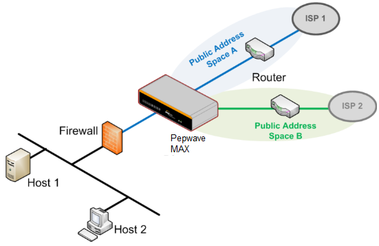
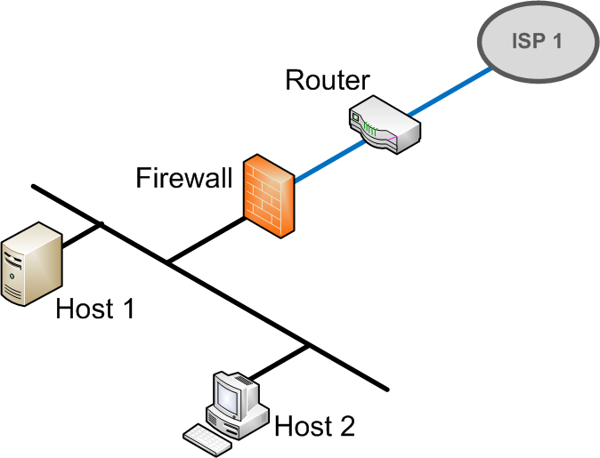
Check the box Enable to enable the Drop-in Mode. After enabling this feature and selecting the WAN for Drop-in mode, various settings including the WAN's connection method and IP address will be automatically updated.
When drop-in mode is enabled, the LAN and the WAN for drop-in mode ports will be bridged. Traffic between the LAN hosts and WAN router will be forwarded between the devices. In this case, the hosts on both sides will not notice any IP or MAC address changes.
After successfully setting up the Peplink MAX as part of the network using drop-in mode, it will, depending on model, support one or more WAN connections. Some MAX units also support multiple WAN connections after activating drop-in mode, though a SpeedFusion license may be required to activate more than one WAN port.
Please note the Drop-In Mode is mutually exclusive with VLAN.
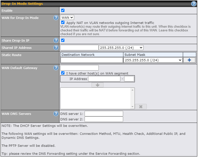
Drop-in Mode Settings | |
Enable | Drop-in mode eases the installation of the Peplink MAX on a live network between the existing firewall and router, such that no configuration changes are required on existing equipment. Check the box to enable the drop-in mode feature. |
WAN for Drop-In Mode | Select the WAN port to be used for drop-in mode. If WAN is selected, the high availability feature will be disabled automatically. |
Shared Drop-In IPA | When this option is enabled, the passthrough IP address will be used to connect to WAN hosts (email notification, remote syslog, etc.). The MAX will listen for this IP address when WAN hosts access services provided by the MAX (web admin access from the WAN, DNS server requests, etc.). To connect to hosts on the LAN (email notification, remote syslog, etc.), the default gateway address will be used. The MAX will listen for this IP address when LAN hosts access services provided by the MAX (web admin access from the WAN, DNS proxy, etc.). |
Shared IP AddressA | Access to this IP address will be passed through to the LAN port if this device is not serving the service being accessed. The shared IP address will be used in connecting to hosts on the WAN (e.g., email notification, remote syslog, etc.). The device will also listen on the IP address when hosts on the WAN access services served on this device (e.g., web admin accesses from WAN, DNS server, etc.). |
WAN Default Gateway | Enter the WAN router's IP address in this field. If there are more hosts in addition to the router on the WAN segment, click the |
WAN DNS Servers | Enter the selected WAN's corresponding DNS server IP addresses. |
 button next to “WAN Default Gateway” and check the other host(s) on the WAN segment box and enter the IP address of the hosts that need to access LAN devices or be accessed by others.
A - Advanced feature, please click the  button on the top right-hand corner to activate.
9.2. Port Settings
To configure port settings, navigate to Network > Port Settings.
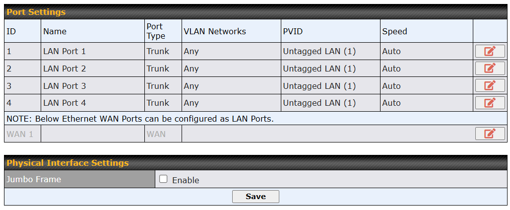
On this screen, you can enable specific ports, determine the speed of the LAN ports, specify whether each port is a trunk or access port, and specify which VLAN each link belongs to, if any.
Untagged frames received by the port are classified to a VLAN indicated by the Port VLAN Identifier (PVID). All frames from the VLAN are untagged on egress. The PVID option is only configurable when Port Type is set to “Trunk”. You may choose to enable Jumbo Frame, which allows larger data packets to be carried.
For supported models, refer to Firmware 8.6.0 – Release Notes, #34968.
9.3. Captive Portal
The captive portal serves as a gateway that clients have to pass if they wish to access the internet using your router. To configure, navigate to Network > LAN > Captive Portal.
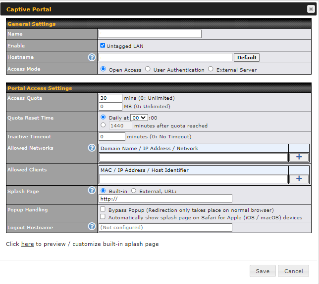
Captive Portal Settings | |
Name | Enter the name for the Captive Portal. |
Enable | Check Enable and then, optionally, select the LANs/VLANs that will use the captive portal. |
Hostname | To customize the portal’s form submission and redirection URL, enter a new URL in this field. To reset the URL to factory settings, click Default. |
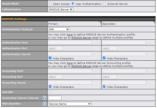
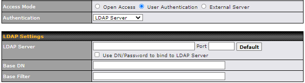
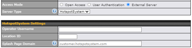
Access Mode | Click Open Access to allow clients to freely access your router. Click User Authentication to force your clients to authenticate before accessing your router. Select External Server to use the Captive Portal with a HotSpot system. As described in the following knowledgebase article: https://forum.peplink.com/t/using-hotspotsystem-wi-fi-on-Peplink-max-routers/ |
Authentication | When selecting the “User Authentication” in the Access Mode field, you will see the available option for the Authentication via drop-down list:
Fill in the necessary information to complete your connection to the server and enable authentication. |
External Server | When selecting the “External Server” in the Access Mode field, you will see the available option for the Service Type via drop-down list:
Fill in the necessary information to complete your connection to the server and enable authentication. |
Access Quota | Set a time and data cap to each user’s Internet usage. |
Quota Reset Time | This menu determines how your usage quota resets. Setting it to Daily will reset it at a specified time every day. Setting a number of minutes after quota reached establishes a timer for each user that begins after the quota has been reached. |
Inactive Timeout | Clients will get disconnected when the inactive the configured time is reached. |
Allowed Networks | Add networks that can bypass the captive Portal in this field. |
Allowed Clients | Add MAC address and /or IP addresses for client devices that are allowed to bypass the Captive Portal. Clients accessing these domains and IP addresses will not be redirected to the splash page. |
Splash Page | Here, you can choose between using the Peplink router’s built-in captive portal and redirecting clients to a URL you define. |
Popup Handling | Configurable options for popup handling: - Automatically show splash page on Safari for Apple (iOS / macOS) devices |
Logout Hostname | A hostname that can be used to log out of the captive portal when being accessed on browser. |
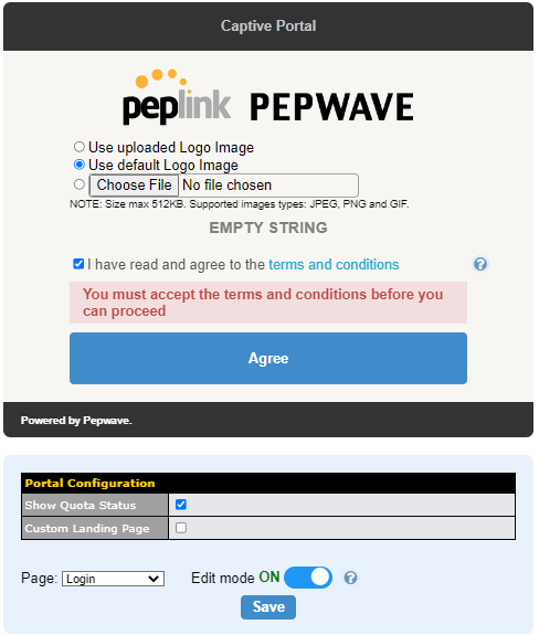
Customize splash page | Click on the provided link in the Captive portal profile to customize the splash page. A new browser tab is opened with a WYSIWYG editor of the splash page. |

 . To delete an existing network from the list of allowed networks, click the
 button next to the listing.