
23. Miscellaneous Settings
The miscellaneous settings include configuration for High Availability, Certificate Manager, service forwarding, service passthrough, GPS forwarding, GPIO, Groupe Networks and SIM Toolkit (depending on whether the feature is supported on the model of Peplink router that is being used).
23.1. High Availability
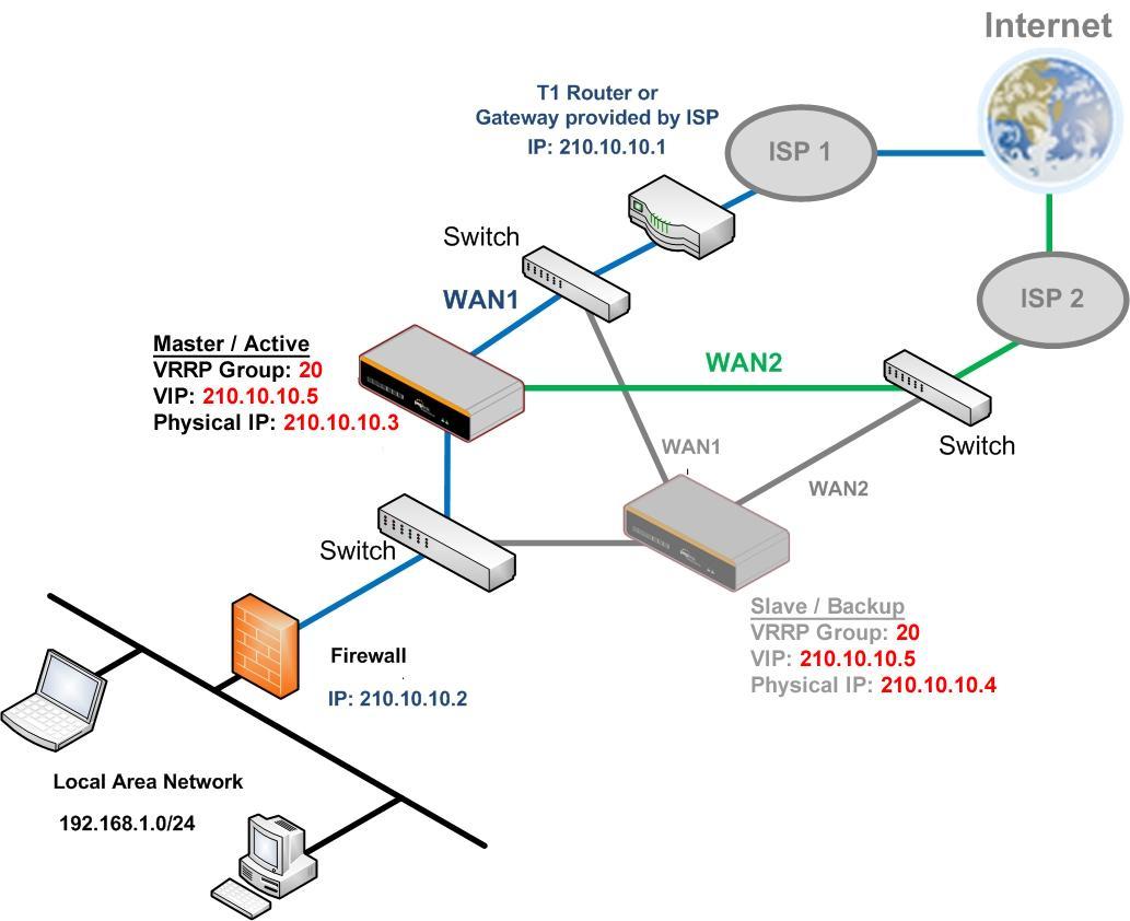
Many Peplink routers support high availability (HA) configurations via an open standard virtual router redundancy protocol (VRRP, RFC 3768). In an HA configuration, two Peplink routers provide redundancy and failover in a master-slave arrangement. In the event that the master unit is down, the slave unit becomes active. High availability will be disabled automatically where there is a drop-in connection configured on a LAN bypass port.
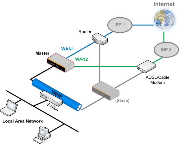
In the diagram, the WAN ports of each Peplink router connect to the router and to the modem. Both Peplink routers connect to the same LAN switch via a LAN port.
An elaboration on the technical details of the implementation of the virtual router redundancy protocol (VRRP, RFC 3768) by Peplink routers follows:
- In an HA configuration, the two Peplink routers communicate with each other using VRRP over the LAN.
- The two Peplink routers broadcast heartbeat signals to the LAN at a frequency of one heartbeat signal per second.
- In the event that no heartbeat signal from the master Peplink router is received in 3 seconds (or longer) since the last heartbeat signal, the slave Peplink router becomes active.
- The slave Peplink router initiates the WAN connections and binds to a previously configured LAN IP address.
- At a subsequent point when the master Peplink router recovers, it will once again become active.
You can configure high availability at Advanced > Misc. Settings > High Availability.
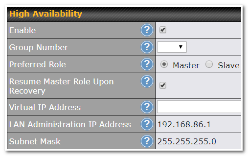
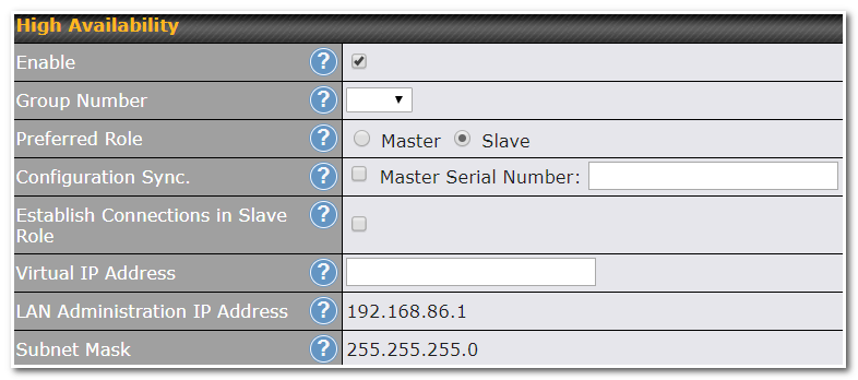
Interface for Master Router | Interface for Slave Router |
|
|
High Availability | |
Enable | Checking this box specifies that the Peplink router is part of a high availability configuration. |
Group Number | This number identifies a pair of Peplink routers operating in a high availability configuration. The two Peplink routers in the pair must have the same Group Number value. |
Preferred Role | This setting specifies whether the Peplink router operates in master or slave mode. Click the corresponding radio button to set the role of the unit. One of the units in the pair must be configured as the master, and the other unit must be configured as the slave. |
Resume Master Role Upon Recovery | This option is displayed when Master mode is selected in Preferred Role. If this option is enabled, once the device has recovered from an outage, it will take over and resume its Master role from the slave unit. |
Configuration Sync. | This option is displayed when Slave mode is selected in Preferred Role. If this option is enabled and the Master Serial Number entered matches with the actual master unit's, the master unit will automatically transfer the configuration to this unit. Please make sure the LAN IP Address and the Subnet Mask fields are set correctly in the LAN settings page. You can refer to the Event Log for the configuration synchronization status. |
Master Serial Number | If Configuration Sync. is checked, the serial number of the master unit is required here for the feature to work properly. |
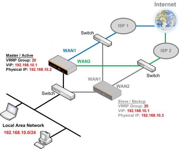
Virtual IP | The HA pair must share the same Virtual IP. The Virtual IP and the LAN Administration IP must be under the same network. |
LAN Administration IP | This setting specifies a LAN IP address to be used for accessing administration functionality. This address should be unique within the LAN. |
Subnet Mask | This setting specifies the subnet mask of the LAN. |
Important Note |
For Peplink routers in NAT mode, the virtual IP (VIP) should be set as the default gateway for all hosts on the LAN segment. For example, a firewall sitting behind the Peplink router should set its default gateway as the virtual IP instead of the IP of the master router.
In drop-in mode, no other configuration needs to be set.
Please note that the drop-in WAN cannot be configured as a LAN bypass port while it is configured for high availability. |
23.2. RADIUS Server
RADIUS Server settings are located at Advanced > Misc. Settings > RADIUS Server.
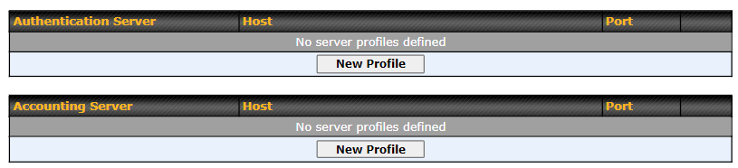
To configure the Authentication Server and Accounting Server, click New Profile to display the following screen:
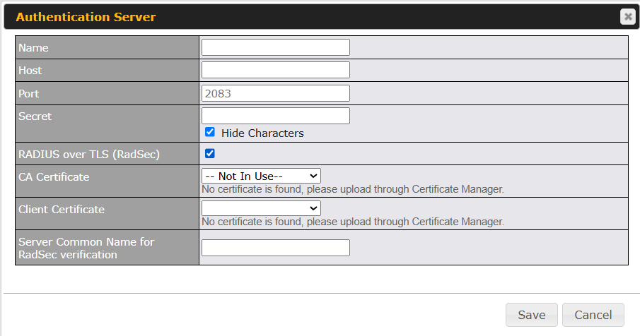
Authentication Server | |
Name | This field is for specifying a name to represent this profile. |
Host | Specifies the IP address or hostname of the RADIUS server host. |
Port | This setting specifies the UDP destination port for authentication requests. By default, the port number is 1812. |
Secret | This field is for entering the secret key for communicating to the RADIUS server. |
RADIUS over TLS (RadSec) | This field is for enabling RadSec. |
CA Certificate | Select a CA Certificate that is defined in Certificate Manager. |
Client Certificate | Select a Client Certificate that is defined in Certificate Manager. |
Server Common Name for RadSec Verification | This field is for entering the server common name. The name will be used for RadSec verification. |
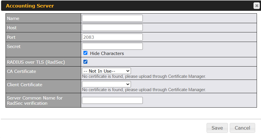
Accounting Server | |
Name | This field is for specifying a name to represent this profile. |
Host | Specifies the IP address or hostname of the RADIUS server host. |
Port | This setting specifies the UDP destination port for accounting requests. By default, the port number is 1813. |
Secret | This field is for entering the secret key for communicating to the RADIUS server. |
RADIUS over TLS (RadSec) | This field is for enabling RadSec. |
CA Certificate | Select a CA Certificate that is defined in Certificate Manager. |
Client Certificate | Select a Client Certificate that is defined in Certificate Manager. |
Server Common Name for RadSec Verification | This field is for entering the server common name. The name will be used for RadSec verification. |
23.3. Certificate Manager
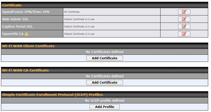
This section allows you to assign certificates for the local VPN, OpenVPN, Captive Portal, MediaFast, ContentHub, Wi-Fi WAN (Client and CA) and web admin SSL for extra security.
Read the following knowledgebase article for full instructions on how to create and import a self-signed certificate: https://forum.peplink.com/t/how-to-create-a-self-signed-certificate-and-import-it-to-a-peplink-product/
Simple Certificate Enrollment Protocol (SCEP) Profiles is to issue certificates automatically from the SCEP server.
General Settings | ||
Name | Profile Name | |
Issuer | ||
Enrollment Server URL | SCEP endpoint to obtain an enrollment certificate. For example, enter something like https://ndes.contoso.com/certsrv/mscep/mscep.dll. | |
Password | SCEP server password. | |
Certificate Renewal Interval | Days to renew/obtain an enrollment certificate. | |
Certificate Subject | ||
Common Name (CN) | Hostname for certificate is issued. (Required) | |
Organization Unit (OU) | Department, section, trademark (Optional) | |
Organization (O) | Organization name for certificate is issued. (Required) | |
Locality (L) | City name (Optional) | |
State (S) | State for certificate is issued. (Required) | |
Country (C) | Country Code in two letters (eg. US) (Required) | |
E-mail (E) | Email address (Optional) | |
Configured Certificate | ||
Certificates | Option to choose which service(s) to apply. | |
23.4. Service Forwarding
Service forwarding settings are located at Advanced > Misc. Settings > Service Forwarding.
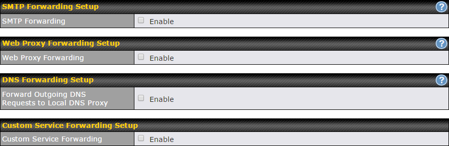
Service Forwarding | |
SMTP Forwarding | When this option is enabled, all outgoing SMTP connections destined for any host at TCP port 25 will be intercepted. These connections will be redirected to a specified SMTP server and port number. SMTP server settings for each WAN can be specified after selecting Enable. |
Web Proxy Forwarding | When this option is enabled, all outgoing connections destined for the proxy server specified in Web Proxy Interception Settings will be intercepted. These connections will be redirected to a specified web proxy server and port number. Web proxy interception settings and proxy server settings for each WAN can be specified after selecting Enable. |
DNS Forwarding | When this option is enabled, all outgoing DNS lookups will be intercepted and redirected to the built-in DNS name server. If any LAN device is using the DNS name servers of a WAN connection, you may want to enable this option to enhance the DNS availability without modifying the DNS server setting of the clients. The built-in DNS name server will distribute DNS lookups to corresponding DNS servers of all available WAN connections. In this case, DNS service will not be interrupted, even if any WAN connection is down. |
Custom Service Forwarding | When custom service forwarding is enabled, outgoing traffic with the specified TCP port will be forwarded to a local or remote server by defining its IP address and port number. |
23.4.1. SMTP Forwarding
Some ISPs require their users to send e-mails via the ISP’s SMTP server. All outgoing SMTP connections are blocked except those connecting to the ISP’s. Peplink routers support intercepting and redirecting all outgoing SMTP connections (destined for TCP port 25) via a WAN connection to the WAN’s corresponding SMTP server.
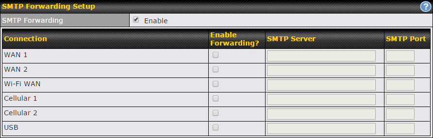
To enable the feature, select Enable under SMTP Forwarding Setup. Check Enable Forwarding for the WAN connection(s) that needs forwarding. Under SMTP Server, enter the ISP’s e-mail server host name or IP address. Under SMTP Port, enter the TCP port number for each WAN.
The Peplink router will intercept SMTP connections. Choose a WAN port according to the outbound policy, and then forward the connection to the SMTP server if the chosen WAN has enabled forwarding. If the forwarding is disabled for a WAN connection, SMTP connections for the WAN will simply be forwarded to the connection’s original destination.
Note |
If you want to route all SMTP connections only to particular WAN connection(s), you should create a custom rule in outbound policy. |
23.4.2. Web Proxy Forwarding
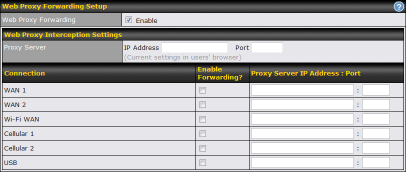
When this feature is enabled, the Peplink router will intercept all outgoing connections destined for the proxy server specified in Web Proxy Interception Settings, choose a WAN connection with reference to the outbound policy, and then forward them to the specified web proxy server and port number. Redirected server settings for each WAN can be set here. If forwarding is disabled for a WAN, web proxy connections for the WAN will be simply forwarded to the connection’s original destination.
23.4.3. DNS Forwarding

When DNS forwarding is enabled, all clients’ outgoing DNS requests will also be intercepted and forwarded to the built-in DNS proxy server.
23.4.4. Custom Service Forwarding

After clicking the enable checkbox, enter your TCP port for traffic heading to the router, and then specify the IP Address and Port of the server you wish to forward the service to.
23.5. Service Passthrough
Service passthrough settings can be found at Advanced > Misc. Settings > Service Passthrough.
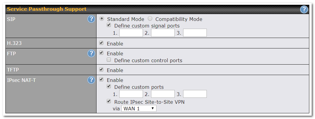
Some Internet services need to be specially handled in a multi-WAN environment. Peplink routers can handle these services such that Internet applications do not notice being behind a multi-WAN router. Settings for service passthrough support are available here.
Service Passthrough Support | |
SIP | Session initiation protocol, aka SIP, is a voice-over-IP protocol. The Peplink router can act as a SIP application layer gateway (ALG) which binds connections for the same SIP session to the same WAN connection and translates IP addresses in the SIP packets correctly in NAT mode. Such passthrough support is always enabled, and there are two modes for selection: Standard Mode and Compatibility Mode. If your SIP server’s signal port number is non-standard, you can check the box Define custom signal ports and input the port numbers to the text boxes. |
H.323 | With this option enabled, protocols that provide audio-visual communication sessions will be defined on any packet network and pass through the Peplink router. |
FTP | FTP sessions consist of two TCP connections; one for control and one for data. In a multi-WAN situation, they must be routed to the same WAN connection. Otherwise, problems will arise in transferring files. By default, the Peplink router monitors TCP control connections on port 21 for any FTP connections and binds TCP connections of the same FTP session to the same WAN. If you have an FTP server listening on a port number other than 21, you can check Define custom control ports and enter the port numbers in the text boxes. |
TFTP | The Peplink router monitors outgoing TFTP connections and routes any incoming TFTP data packets back to the client. Select Enable if you want to enable TFTP passthrough support. |
IPsec NAT-T | This field is for enabling the support of IPsec NAT-T passthrough. UDP ports 500, 4500, and 10000 are monitored by default. You may add more custom data ports that your IPsec system uses by checking Define custom ports. If the VPN contains IPsec site-to-site VPN traffic, check Route IPsec Site-to-Site VPN and choose the WAN connection to route the traffic to. |
23.6. GPIO
GPIO (General Purpose Input/Output) and Ignition Sensing are specifically designed for vehicular, IoT, and industrial deployments. For more information, kindly refer to the link below:
https://download.peplink.com/resources/gpio_and_ignition_sensing_guide.pdf
Ignition Sensing installation
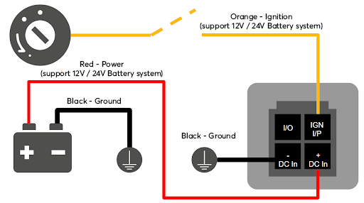
Function | Colour Wire | ||
| I/O | optional * | Brown |
IGN I/P | connected to positive feed on the ignition ** | Orange | |
DC IN | connected to permanent negative feed (ground) | Black | |
DC IN + | connected to permanent positive feed (power) | Red | |
* Currently not functional; will be used for additional features in future firmware. ** Connecting IGN I/P is optional and is needed only if the Ignition Sensing feature is configured. | |||
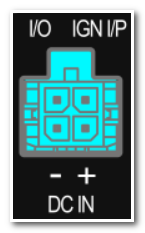
Connectivity diagram for devices with 4-pin connector
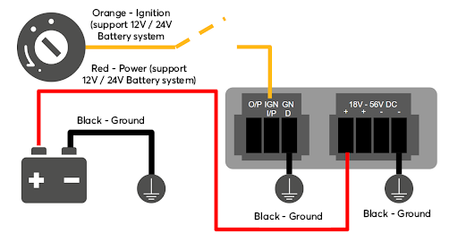
Connectivity diagram for devices with terminal block connection
GPIO Menu
Note: This feature is applicable for certain models that come with a GPIO interface.
Ignition Sensing options can be found in Advanced > Misc. Settings > GPIO.
The configurable option for Ignition Input is Delay; the time in seconds that the router stays powered on after the ignition is turned off.
a.) Ignition sensing: 9-30V active high for IGN purpose
b.) Input Sensing: I/O input
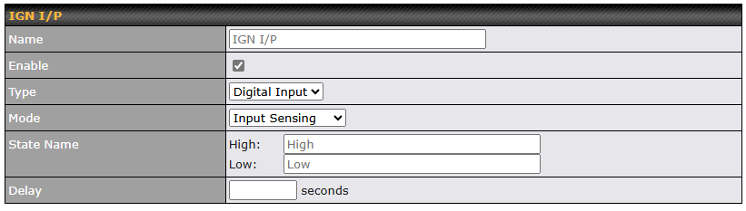
The O/P (connected to the I/O pin on a 4 pin connector) can be configured as a digital input, a digital output, or an analog input.
Digital Input – the connection supports input sensing; it reads the external input and determines if the settings should be ‘High’ (on) or ‘Low’ (off).
State Name – This field is to custom names shows on event log when digital input is high or low.

Note: The Digital Output state (on/off) upon rebooting the device may vary depending on the model, eg. MAX BR1 MK2 = Persistent; MAX Transit Mini with ContentHub = Reset to default, etc.
Analog Input - to be confirmed. In most cases, it should read the external input and determine the voltage level.
23.7. NTP Server
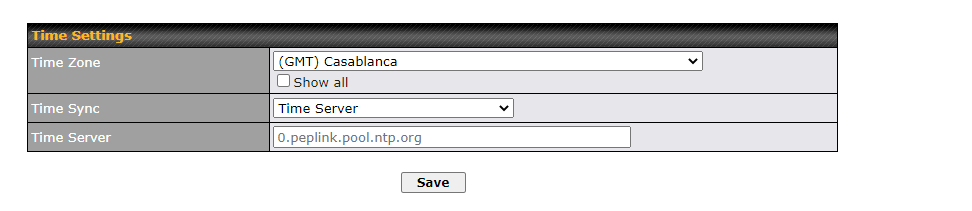
Peplink routers can now serve as a local NTP server. Upon start up, it is now able to provide connected devices with the accurate time, precise UTC from either an external NTP server or via GPS and ensuring that connected devices always receive the correct time.
Compatible with: BR1 ENT, BR1 Pro CAT-20/5G, 700 HW3, HD2/4, Transit
NTP Server setting can be found via: Advanced > Misc. Settings > NTP Server

Time Settings can be found at System > Time > Time Settings
23.8. Grouped Networks
Advanced > Grouped Networks allows you to configure destination networks in a grouped format.

Select Add Group to create a new group with single IP addresses, subnets from different VLANs, or domain names.
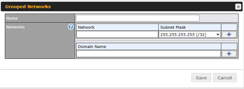

The created network groups can be used in outbound policies and firewall rules.
23.9. SIM Toolkit
The SIM Toolkit, accessible via Advanced > Misc Settings > SIM Toolkit, supports two functionalities, USSD and SMS.
USSD
Unstructured Supplementary Service Data (USSD) is a protocol used by mobile phones to communicate with their service provider’s computers. One of the most common uses is to query the available balance.
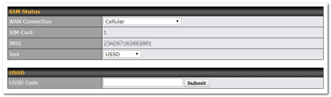
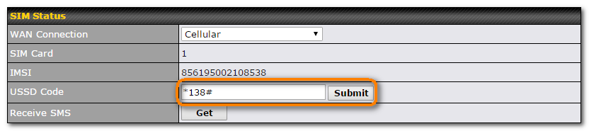
Enter your USSD code under the USSD Code text field and click Submit.
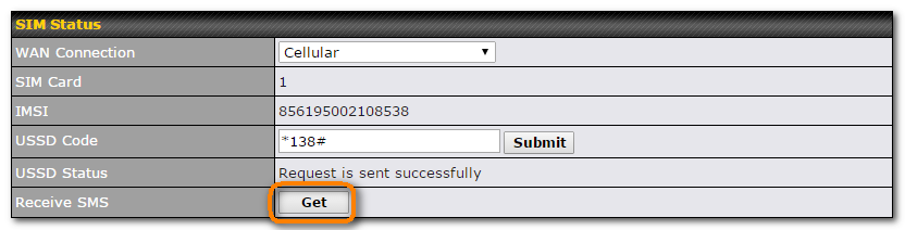
You will receive a confirmation. To check the SMS response, click Get.
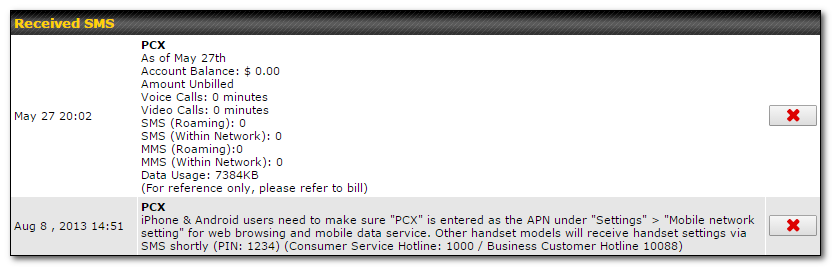
After a few minutes you will receive a response to your USSD code.
SMS
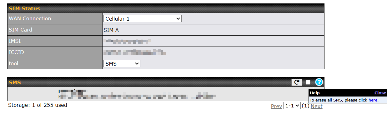
The SMS option allows you to read SMS (text) messages that have been sent to the SIM in your Pepwave router. Clicking the  will allow users to erase all SMS on the SIM card.
23.10. UDP Relay
You may define the UDP relay by clicking the Advanced > Misc Settings > UDP Relay. You can click  to enable the UDP relay to relay UDP Broadcast or Multicast traffic for LAN/VLAN/SpeedFusion VPN.

Click “New UDP Relay Rule” to define the relay rule.

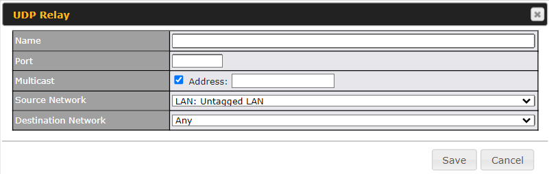
UDP Relay | |
Name | This field is for specifying a name to represent this profile. |
Port | This field is to enter the specific port number for the UDP relay. |
Multicast | If Multicast is not selected, it will broadcast relay rule. If Multicast is selected, you may need to enter a valid multicast address. |
Secure Network | Select the specific connection as a source network to where the device is to relay UDP Broadcast packets. |
Destination Network | You may select the specific connection from the drop-down list or may custom combination network as a destination network that receives the UDP packet relays. |