
12. IPsec VPN
IPsec VPN functionality securely connects one or more branch offices to your company's main headquarters or to other branches. Data, voice, and video communications between these locations are kept safe and confidential across the public Internet.
IPsec VPN on Peplink routers is specially designed for multi-WAN environments. For instance, if a user sets up multiple IPsec profiles for a multi-WAN environment and WAN1 is connected and healthy, IPsec traffic will go through this link. However, should unforeseen problems (e.g., unplugged cables or ISP problems) cause WAN1 to go down, our IPsec implementation will make use of WAN2 and WAN3 for failover.
12.1. IPsec VPN Settings
Many Peplink products can make multiple IPsec VPN connections with Peplink, Peplink, Cisco, and Juniper routers. Note that all LAN subnets and the subnets behind them must be unique. Otherwise, VPN members will not be able to access each other. All data can be routed over the VPN with a selection of encryption standards, such as 3DES, AES-128, and AES-256. To configure IPsec VPN on Peplink devices that support it, navigate to Advanced>IPsec VPN.
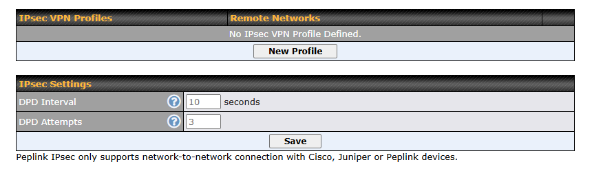
Click the New Profile button to create new IPsec VPN profiles that make VPN connections to remote Peplink, Cisco, or Juniper routers via available WAN connections. To edit any of the profiles, click on its associated connection name in the leftmost column.
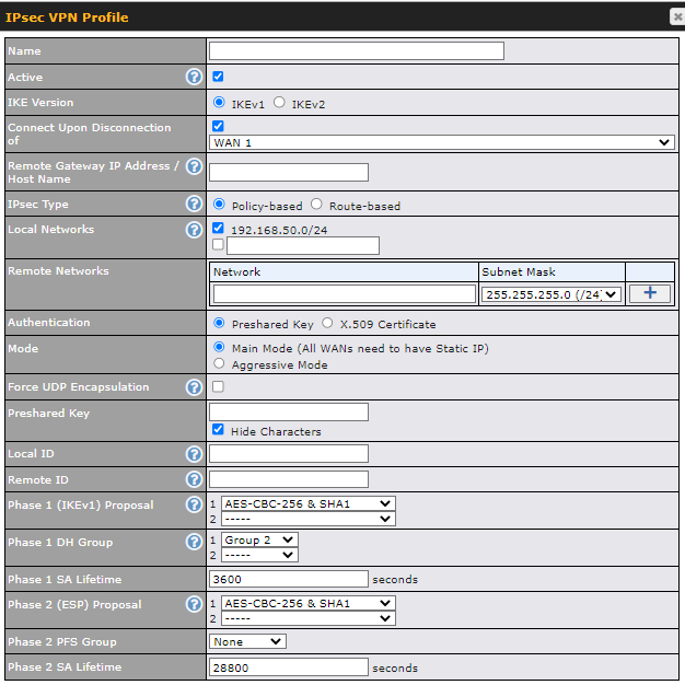
IPsec VPN Profile Settings | |
Name | This field is for specifying a local name to represent this connection profile. |
Active | When this box is checked, this IPsec VPN connection profile will be enabled. Otherwise, it will be disabled. |
IKE Version | Two versions of the IKE standards are available:
|
Connect Upon Disconnection of | Check this box and select a WAN to connect to this VPN automatically when the specified WAN is disconnected. |
Remote Gateway IP Address / Host Name | Enter the remote peer’s public IP address. For Aggressive Mode, this is optional. |
IPsec Type | Policy-based - (default) All the matched traffic as defined in Local Networks and Remote Networks will be routed to this IPsec connection, this cannot be overridden by other routing methods. Route-based - Outbound Policy rule is required to route traffic to this tunnel and comes with more flexibility to control how to route traffic compared to Policy-based. If you want to modify the traffic selector instead of using the default (0.0.0.0/0). Note: This option is available for certain following models only:
|
Local Networks | Enter the local LAN subnets here. If you have defined static routes, they will be shown here. Using NAT, you can map a specific local network / IP address to another, and the packets received by remote gateway will appear to be coming from the mapped network / IP address. This allows you to establish IPsec connection to a remote site that has one or more subnets overlapped with local site. Two types of NAT policies can be defined: One-to-One NAT policy: if the defined subnet in Local Network and NAT Network has the same size, for example, policy "192.168.50.0/24 > 172.16.1.0/24" will translate the local IP address 192.168.50.10 to 172.16.1.10 and 192.168.50.20 to 172.16.1.20. This is a bidirectional mapping which means clients in remote site can initiate connection to the local clients using the mapped address too. Many-to-One NAT policy: if the defined NAT Network on the right hand side is an IP address (or having a network prefix /32), for example, policy "192.168.1.0/24 > 172.168.50.1/32" will translate all clients in 192.168.1.0/24 network to 172.168.50.1. This is a unidirectional mapping which means clients in remote site will not be able to initiate connection to the local clients. |
Remote Networks | Enter the LAN and subnets that are located at the remote site here. |
Authentication | To access your VPN, clients will need to authenticate by your choice of methods. Choose between the Preshared Key and X.509 Certificate methods of authentication. |
Mode | Choose Main Mode if both IPsec peers use static IP addresses. Choose Aggressive Mode if one of the IPsec peers uses dynamic IP addresses. |
Force UDP Encapsulation | For forced UDP encapsulation regardless of NAT-traversal, tick this checkbox. |
Pre-shared Key | This defines the peer authentication pre-shared key used to authenticate this VPN connection. The connection will be up only if the pre-shared keys on each side match. |
Remote Certificate (pem encoded) | Available only when X.509 Certificate is chosen as the Authentication method, this field allows you to paste a valid X.509 certificate. |
Local ID | In Main Mode, this field can be left blank. In Aggressive Mode, if Remote Gateway IP Address is filled on this end and the peer end, this field can be left blank. Otherwise, this field is typically a U-FQDN. |
Remote ID | In Main Mode, this field can be left blank. In Aggressive Mode, if Remote Gateway IP Address is filled on this end and the peer end, this field can be left blank. Otherwise, this field is typically a U-FQDN. |
Phase 1 (IKE) Proposal | In Main Mode, this allows setting up to six encryption standards, in descending order of priority, to be used in initial connection key negotiations. In Aggressive Mode, only one selection is permitted. |
Phase 1 DH Group | This is the Diffie-Hellman group used within IKE. This allows two parties to establish a shared secret over an insecure communications channel. The larger the group number, the higher the security. Group 2: 1024-bit is the default value. Group 5: 1536-bit is the alternative option. |
Phase 1 SA Lifetime | This setting specifies the lifetime limit of this Phase 1 Security Association. By default, it is set at 3600 seconds. |
Phase 2 (ESP) Proposal | In Main Mode, this allows setting up to six encryption standards, in descending order of priority, to be used for the IP data that is being transferred. In Aggressive Mode, only one selection is permitted. |
Phase 2 PFS Group | Perfect forward secrecy (PFS) ensures that if a key was compromised, the attacker will be able to access only the data protected by that key. None - Do not request for PFS when initiating connection. However, since there is no valid reason to refuse PFS, the system will allow the connection to use PFS if requested by the remote peer. This is the default value. Group 2: 1024-bit Diffie-Hellman group. The larger the group number, the higher the security. Group 5: 1536-bit is the third option. |
Phase 2 SA Lifetime | This setting specifies the lifetime limit of this Phase 2 Security Association. By default, it is set at 28800 seconds. |

WAN Connection Priority | |
WAN Connection | Select the appropriate WAN connection from the drop-down menu. |
IPsec Settings | |
DPD Interval | Time interval between Dead Peer Detection (DPD) messages (R_U_THERE in IKEv1 or INFORMATIONAL in IKEv2) that check if the peer is still active when no other traffic is present. Default: 10 seconds (2–30 seconds) |
DPD Attempts | Total number of DPD messages sent before the peer is considered unreachable. Default: 3 times (2-10 times) |