27. Switch
27.1. Switch Controller
Navigate to Switch Tab > Switch Controller > Controller.
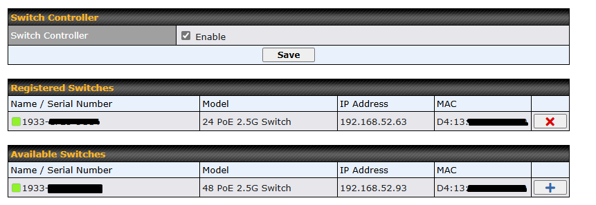
Switch Controller | |
Registered Switches | List of registered switches. Press “X” to remove the selected switch from the list. |
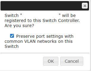
Available Switches | List of available switches connected to the device. Press “+” to register the selected switch to the Registered Switches list. Note: When option “Preserve port settings with common VLAN networks on this Switch” is ticked when registering the selected switch, the port settings whose VLANs are defined in Switch Controller will be preserved. Otherwise, they will be replaced by VLAN 1. |
NOTE: PoE 2.5G Switch will only be managed by either InControl or Device switch controller. Do not enable the Switch Controller if the switch needs to be managed by InControl.
27.2. Admin Security
Navigate to Switch Tab > Switch Controller > Admin Security.
There are two types of user accounts available for accessing the Web Admin: admin and user. The admin login has full administrative access, while the user login is read-only. The user level can access only the device’s status information; users cannot make any changes on the device.
A web login session will be logged out automatically when it has been idle longer than the Web Session Timeout. Before the session expires, you may click the Logout button in the web admin to exit the session.
0 hours 0 minutes signifies an unlimited session time. This setting should be used only in special situations, as it will lower the system security level if users do not log out before closing the browser. The default is 4 hours, 0 minutes.
For security reasons, after logging in to the web admin Interface for the first time, it is recommended to change the administrator password. Configuring the administration interface to be accessible only from the LAN can further improve system security. Administrative settings configuration is located at System>Admin Security.
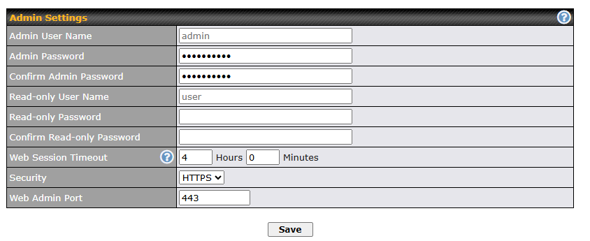
Admin Settings | |
Admin User Name | Admin User Name is set as admin by default, but can be changed, if desired. |
Admin Password | This field allows you to specify a new administrator password. |
Confirm Admin Password | This field allows you to verify and confirm the new administrator password. |
Read-only User Name | Read-only User Name is set as user by default, but can be changed, if desired. |
Read-only Password | This field allows you to specify a new user password. Once the user password is set, the read-only user feature will be enabled. |
Confirm Read-only Password | This field allows you to verify and confirm the new user password. |
Web Session Timeout | This field specifies the number of hours and minutes that a web session can remain idle before the Pepwave router terminates its access to the web admin interface. By default, it is set to 4 hours. |
Security | This option is for specifying the protocol(s) through which the web admin interface can be accessed:
Default will be HTTPS. |
Web Admin Port | This field is for specifying the port number on which the web admin interface can be accessed. |
27.3. Switch Information
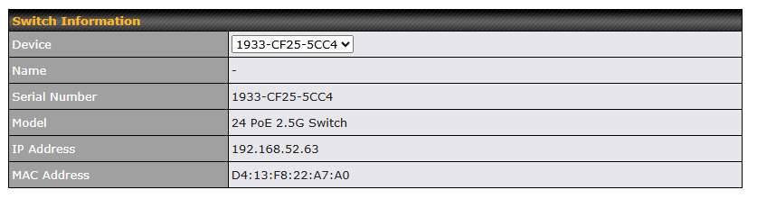
Switch Information | |
Device | Drop down list to select Switch to be configured. |
Name | Name of the switch.(not sure where to define) |
Serial Number | Selected switch serial number. |
Model | Selected switch model. |
IP Address | Uplink IP address of the selected switch. |
MAC Address | Selected switch MAC address. |
27.4. STP
Navigate to Switch Tab > STP.
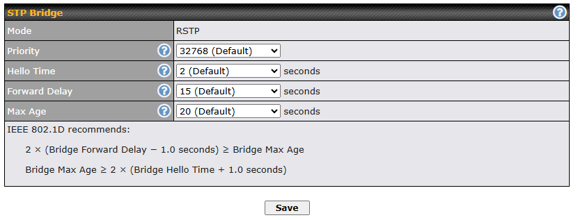
STP Bridge | |
Mode | RSTP |
Priority | This field specifies the bridge priority for root switch election. The switch with the lowest bridge priority is elected as the root switch (Default value: 32768). |
Hello Time (A) | Time between each exchange of bridge protocol data units (BPDU). (Default value: 2 seconds). |
Forward Delay (A) | Delay used by STP Bridges to transit Root and Designated Ports to Forwarding. (Default value: 15 seconds). |
Max Age (A) | Maximum age of the information transmitted by the bridge when it is the Root Bridge. (Default value: 20 seconds). |
(A) – Advanced feature. Click the  button on the top right-hand corner to activate.
27.5. Switch Ports
Navigate to Switch Tab > Interfaces > Switch Ports.
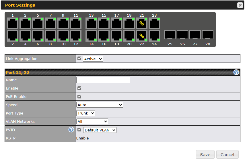
For each port, you can set PoE scheduling, port type (Trunk and Access), as well as the VLAN which they belong to.
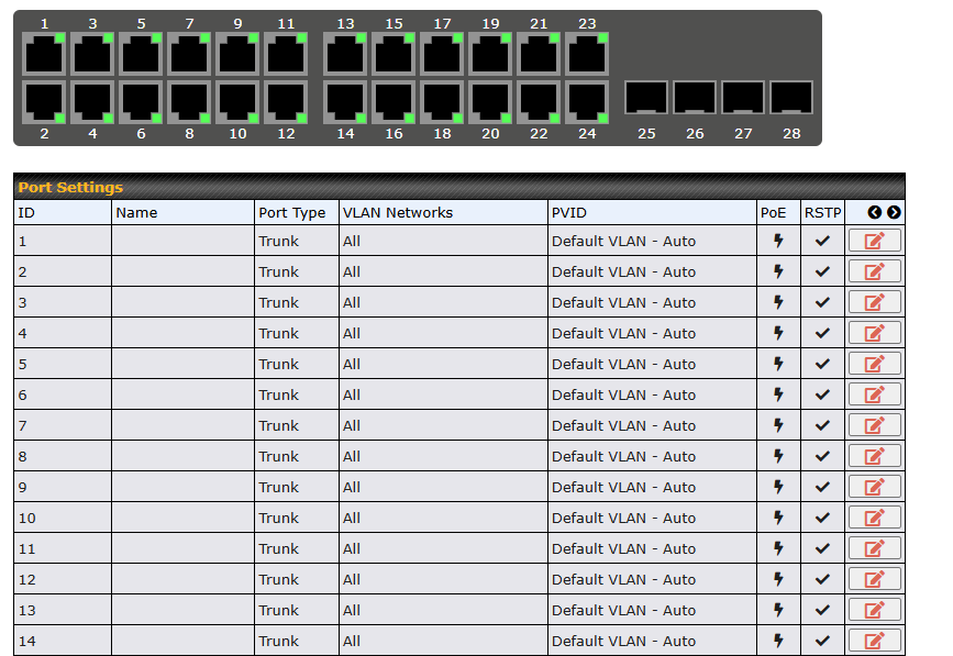
To configure a port, you may click on the port icon or the pen icon from the Port Settings table to show the Port parameters.
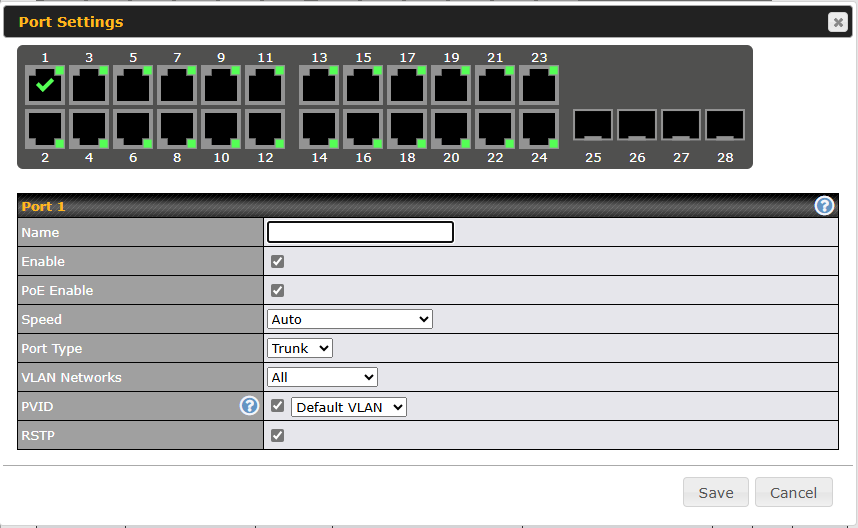
Port Settings | |
Name | Set a name for the port |
Enable checkbox | Enables / Disables the Port |
PoE Enable checkbox | Enables / Disables PoE on the Port |
Speed^ | Set the port speed to Auto, 10 Mbps half/full duplex or 100 Mbps half/full duplex, or 1GB full duplex. |
Port Type | Set as Trunk or Access |
VLAN Networks | Designate one or more VLANs to be used on this port. |
PVID** | Untagged frames received by the port are classified to a VLAN indicated by Port VLAN Identifier (PVID). All frames from the VLAN are untagged on egress.** |
RSTP checkbox | Enables or Disables Rapid Spanning Tree Protocol |
** PVID option is only configurable when Port Type is set to “Trunk”.
^ Configuration options on certain ports are configurable port speeds to 2.5 Gbps. May refer to the datasheet or label below switch ports.
^ Configurable options on SFP+ ports are similar to the above, but configurable port speeds are between 100 Mbps Full Duplex up to 10 Gbps Full Duplex.
27.6. LACP (802.3ad) Configuration
LACP is part of the IEEE specification 802.3ad and allows you to bundle several physical ports to form a single logical channel.
Bundling multiple physical ports into a single logical link allows you to increase throughput beyond the limitations of a single connection and provides redundancy in case one link goes down.
Select multiple ports by clicking on them and selecting the Link Aggregation checkbox to enable link aggregation for the selected ports.