
13. Settings (Group Level)
This chapter covers the group-level Settings menu, which administers a group as a whole: its devices, how InControl 2 communicates with them, their firmware, the group administrators and the change history. Every screen in this chapter operates at group level, so a setting made once applies to all targeted devices in the group. Several screens show no settings until their management checkbox is selected.
Settings made on the device are overwritten where InControl 2 manages them. Where InControl 2's management option is enabled for Wi-Fi AP SSID and Radio, SpeedFusion VPN, Outbound Policy, Firewall Rules, Web Admin Settings or Time zone, InControl 2 overwrites any change made directly on the device with the settings defined in InControl 2. The full rule set is under Bulk Configurator below (13.12 Bulk Configurator).
When two settings target the same device
Several configuration options under Group > Settings can select the same device more than once. Each option resolves the overlapping device precedence by its own rule:
Screen | Which setting the device takes | See |
Bulk Configurator | The topmost configuration in the list | |
GPIO | The topmost profile in the list | |
Serial-port-based InTouch | The first enabled profile from the top. The device-level setting overrides the group | |
Scheduled Reboot (Device System Management) | The first matched schedule instruction | |
Geo-fencing | Notifications are sent for every fence. Wi-Fi AP and tagging actions run for the topmost fence only |
13.1. Device Management (Group Level)
Lists every device in the group and provides the entry points for adding devices, or for exporting or updating device information in bulk. The grid includes Wi-Fi channel figures and client counts, so it also serves as a fleet overview. The Redirecting Devices to InControl Appliance notice above the grid refers to appliance redirection, which is configured under External InControl Appliance Settings on the Device System Management screen (13.4.9 External InControl Appliance Settings).
Where to find it
Group > Settings > Device Management
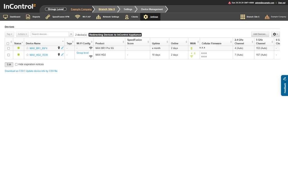
The device list. The columns to the right of Device Name continue past the visible edge of the table.
13.1.1. What This Screen Shows
The page contains one grid, Devices, with a device count above it, for example 2 device(s).

The Devices grid with two devices listed. The columns run from Status and Device Name to the 2.4 GHz, 5 GHz and 6 GHz Channel columns.
Column | What it shows |
Status | Device status icons. Each icon has a tooltip naming the condition it reports. The full icon set is listed under Status icons below |
Device Name | The device name. Each name links to that device |
Tags | Tags applied to the device |
Wi-Fi Config | The source of the device's Wi-Fi configuration. A device configured at group level shows Group level, which links to the group's Wi-Fi AP SSID settings (7.2 Group-wide SSID Settings) |
Product | Product model, for example MAX BR1 Pro 5G |
SpeedFusion Score | SpeedFusion Score for the device |
Uptime | Device uptime, shown as a relative time |
Online | Online time, shown as a relative time |
WAN | WAN information |
Cellular Firmware | Cellular module firmware version. A device with two modules lists both |
2.4 GHz Channel | Channel in use, with the selection method in brackets, for example 4 (Auto) |
5 GHz Channel | Channel in use, with the selection method in brackets |
6 GHz Channel | Channel in use. - when the band is not in use |
Usage | Current throughput, for example 7.0 kbps |
Clients | Client count |
Firmware | Device firmware version and build |
Last Config Applied | When configuration was last applied, shown as a relative time |
Relative times show the exact timestamp as a tooltip. Hover over a value such as 4 days ago to display the full date and time.
13.1.2. Status Icons
A status icon set sits above the grid with a Match all option. Each icon has a tooltip stating its meaning. The tables below list each tooltip and serve as the reference for the Status column.
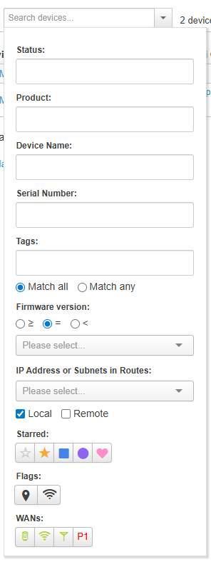
The panel opened from the arrow beside the search box. Match all and Match any are under Tags, and the Starred, Flags and WANs icon sets are at the bottom.
Device state and enabled features:
Tooltip | Reports |
Online | The device is online |
With GPS data | The device is reporting GPS data |
Follow another device's GPS location | The device takes its location from another device rather than from its own GPS |
Wi-Fi AP enabled | Wi-Fi AP is enabled on the device |
Captive portal enabled | A captive portal is enabled on the device |
Router mode | The device is in router mode |
Scheduled reboot | A reboot schedule is set on the device |
eSIM Pooled Plan | The device is on an eSIM pooled plan |
Cellular WAN connections are locked to specific SIM cards. | The cellular WAN connections are locked to specific SIM cards |
Conditions that need attention:
Tooltip | Reports |
Device's web admin password remains with the default one. | The device web admin password has never been changed |
Invalid license | The device has an invalid licence |
Firmware upgrade is available. | A newer firmware version is available for the device |
One or more Starlink terminal connected to this device has firmware pending to install. | A connected Starlink has firmware waiting to install |
One or more WANs hit 100% usage and restricted to routing management traffic only. | A WAN has reached its usage allowance and carries management traffic only |
Configuration state. Check these when a device does not take group settings:
Tooltip | Reports |
Config patches available | Configuration patches are waiting for the device |
Configuration to device stopped. Configuration rolled back. | Configuration was stopped and the previous configuration was restored |
InControl stopped to apply configurations to device. | InControl 2 has stopped applying configuration to the device |
Device disabled configurations from InControl | The device is refusing configuration from InControl 2 |
WAN icons:
Tooltip | Reports |
Ethernet | An Ethernet WAN |
Wi-Fi | A Wi-Fi WAN |
Cellular | A cellular WAN |
Priority-1 down WANs | WANs at priority 1 that are down |
13.1.3. Controls on This Screen
Control | What it does |
Search devices... | Filters the device list |
Search options (arrow beside Search devices...) | Opens a panel with Match all and Match any under Tags, and the Starred, Flags and WANs icon sets listed under Status icons above |
Tag | Opens the Tag menu, described under The Tag menu below. Disabled until a device row is selected |
Actions | Opens the Actions menu, described under The Actions menu below. Disabled until a device row is selected |
Add Devices... | Opens the Group > Settings > Add Devices page, headed Add Devices Into Groups and described under Add Devices below (13.2 Add Devices (Group Level)) |
Edit | Toggles the grid's edit mode. When clicked, the row checkboxes, Tag, Actions and Update device info by CSV file are hidden |
Hide expiration notices | Suppresses expiration notices in this list. Shown beside Edit when the page opens |
Download as CSV | Exports the device list as a CSV file |
Update device info by CSV file | A link under the device table that uploads device names and locations from a CSV file. See Update device info by CSV file below |
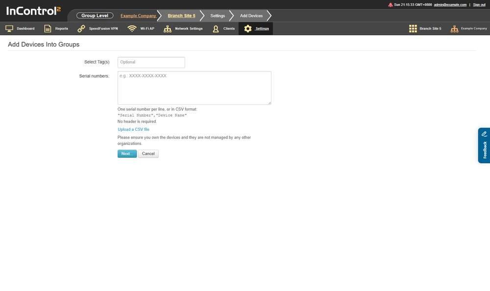
The Add Devices page opened from Add Devices... The breadcrumb reads Settings > Add Devices, and the page is headed Add Devices Into Groups.
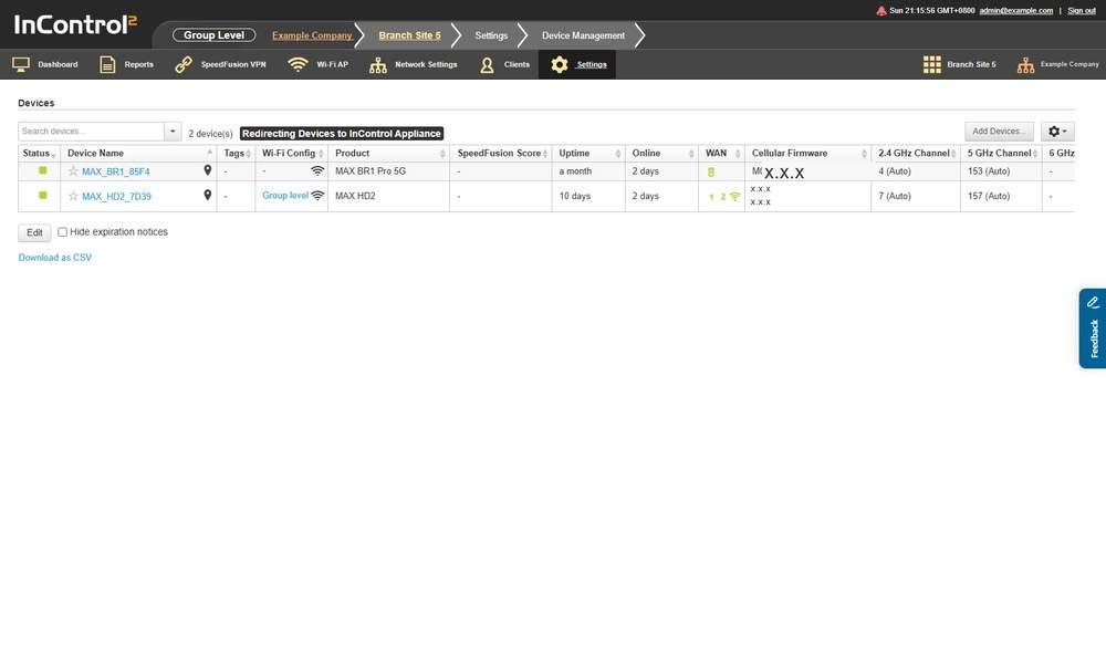
After Edit is clicked, the row checkboxes, Tag, Actions and Update device info by CSV file are hidden. Hide expiration notices remains beside Edit.
13.1.4. Selecting Devices for a Bulk Action
Tag and Actions are the bulk controls on this screen. Both are disabled until at least one device row is selected.
Selecting a row changes the area above the grid:
- A Selected N devices: line appears, for example Selected 1 devices:, with the count and the names of the selected devices.
- Clear all selections appears beside it and clears the selection.
- Tag and Actions become active.
13.1.5. The Tag Menu
Tags the selected devices in bulk. The menu has three entries.
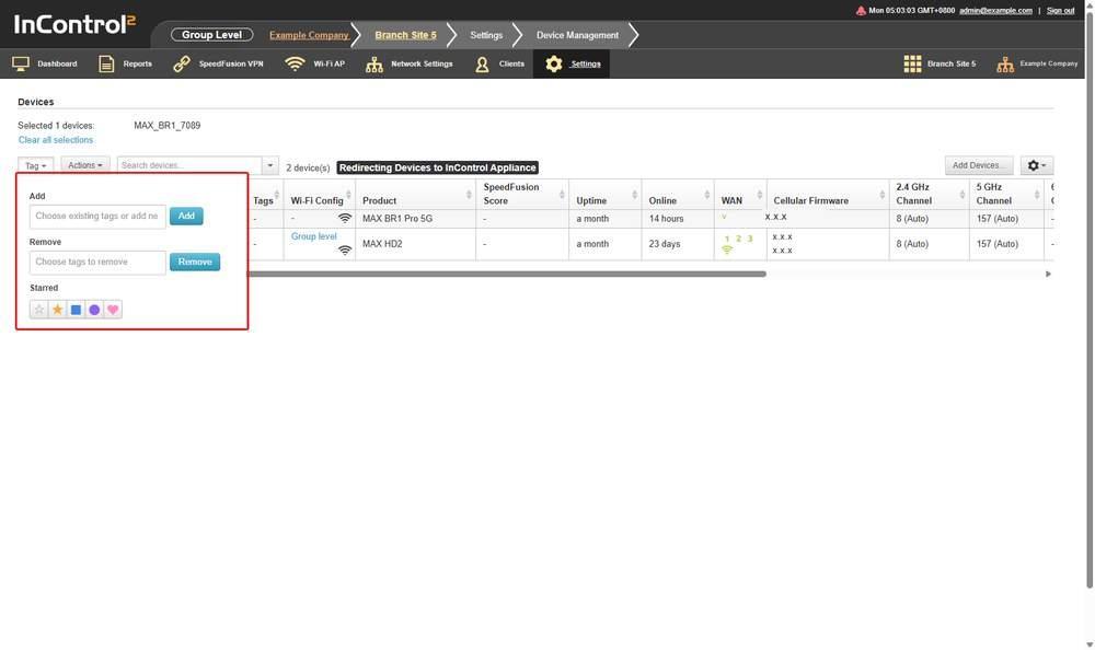
The Tag menu with one device selected, outlined in red. Add and Remove each pair a tag entry field with a button of the same name.
Entry | What it holds |
Add | A tag entry field and an Add button, which applies the tags to the selected devices |
Remove | A tag entry field and a Remove button, which removes the tags from the selected devices |
Starred | A row of five markers, with no button of its own |
Device Selection on most other screens in this chapter selects devices by tag, so tags applied here determine which devices later settings reach.
13.1.6. The Actions Menu
Runs a single bulk action against the selected devices.
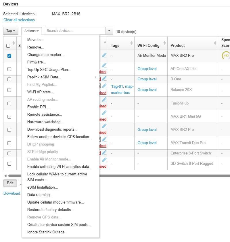
The Actions menu with one device selected. The Selected 1 devices line above the grid names the device, and entries that do not apply to it are greyed.
The entry list is not fixed. Entries appear according to the device types in the group, and entries that do not apply to the selected device are greyed rather than hidden. A group with switches and access points adds AP routing mode..., DHCP snooping and STP bridge priority, which a group of routers only does not show. The table below lists all entries. The entries shown in a given group depend on its device types.
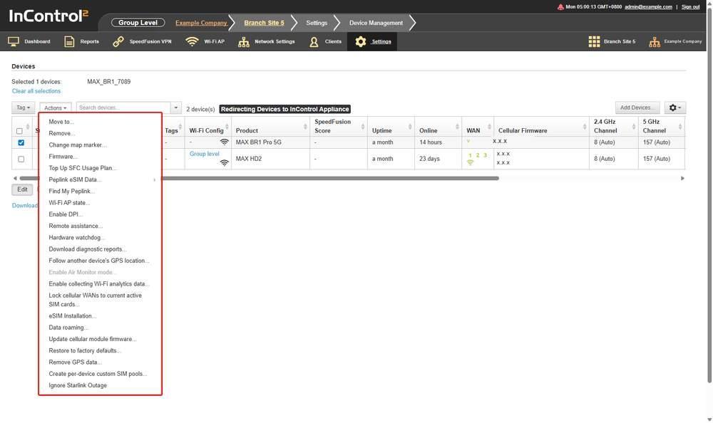
The full Actions menu, outlined in red, with Restore to factory defaults... near the bottom.
Every entry except Firmware... and Peplink eSIM Data... opens a form. Each form can be closed with Cancel or Close, so no entry commits a change on the click alone. Firmware... opens the device's Firmware Management screen (16.1 Firmware Management), and Peplink eSIM Data... opens a submenu of three entries.
Cancel changes nothing. The commit button is named for the action: Save on most forms, and Move, Create or Activate on the three that do something other than save a setting.
Check the Selected N devices: line first. Every entry applies to the whole selection. This is most important for Restore to factory defaults..., Remove... and the entries beginning Top Up.
13.1.7. What Each Entry Opens
Entry | Opens |
Move to... | A target group dropdown, plus Retain tags and InControl managed settings, Retain device name and Retain device location. The form warns that the move may move some group level SpeedFusion VPN profiles to organization level to keep connections up. The button is Move |
Remove... | Removes the selected devices from InControl 2. The form states that all data collected from them will be cleared from the system, and asks whether InControl 2 managed settings on the devices should be removed or retained. The default is retained. The button is OK |
Change map marker… | A grid of eleven marker icons: plain pin, aircraft, bus, fire appliance, car, police car, boat, taxi, van, truck and ambulance. The form has no text controls |
Firmware... | Not a form. Opens the selected device's Firmware Management screen, described in the Device-Level chapter (16.1 Firmware Management). Applies to routers and switches |
Top Up SFC Usage Plan... | Adds SpeedFusion Connect usage to the selected devices |
Peplink eSIM Data... | Not a form. A parent entry with three entries: Top Up Peplink NA & EU eSIM Data Plan..., Top Up Peplink Global eSIM Data Plan... and Add device to Peplink eSIM Data Pooled Plan... |
Find My Peplink... | Locates the selected devices. Greyed on devices that do not support it |
Wi-Fi AP state... | On or Off, with the affected devices named in the form |
AP routing mode... | Sets the routing mode on access points. Greyed unless the selection includes one |
Enable DPI... | Enable or Disable for deep packet inspection. The form lists its firmware requirements: AP One on 3.7.3 or 3.8.1 and above, and listed Balance and MAX models on 7.0.1 and above |
Remote assistance... | Enable or Disable. Enable offers a choice between a day count with direct connection disallowed, or direct connection allowed with remote assistance on until manually turned off |
Hardware watchdog... | Enable or Disable |
Download diagnostic reports... | Downloads diagnostic reports from the selected devices |
Follow another device's GPS location... | A device picker with Followed Device and Unfollow as the two states |
DHCP snooping | An Enable checkbox. The form states that it is for SD Switches only, and that it prevents unauthorised DHCP servers from offering addresses to clients: when enabled, DHCP server discovery messages reach only the switch ports set to Allow DHCP Server. Off by default |
STP bridge priority | A Priority dropdown with the sixteen standard values, 0 to 61440 in steps of 4096. The switch with the lowest priority is elected root. Default 32768 |
Enable Air Monitor mode... | Puts supported devices into Air Monitor mode. Greyed on devices without it |
Enable collecting Wi-Fi analytics data... | Enable or Disable. Requires firmware 7.0 and above on Balance and MAX, 3.5.4 and above on AP devices |
Lock cellular WANs to current active SIM cards... | Lock, so the device connects only on the currently active SIM cards, or Unlock, so it connects on any SIM card |
eSIM Installation... | A short question form, described below |
Data roaming... | Enable or Disable, applied to every cellular WAN on every selected device |
Update cellular module firmware... | Updates the cellular module, which is separate from device firmware |
Restore to factory defaults... | Returns the selected devices to factory settings |
Remove GPS data... | Clears stored GPS history. Greyed where there is none |
Create per-device custom SIM pools... | The largest form in the menu, described below |
Ignore Starlink Outage | Enable or Disable, Disable by default. Available for routers, greyed for switches |
Caution: Clear Retain tags and InControl managed settings on Move to... only when intended. The devices then arrive in the new group without their tags and InControl 2 managed settings, and the organization Operation Log records All InControl managed settings are removed from the device(s). Tag based Device Selection rules in the new group do not match these devices until they are tagged again.
Caution: Restore to factory defaults... returns every device on the Selected N devices: line to factory settings, and each listed device loses its configuration. Check that line before clicking the commit button.
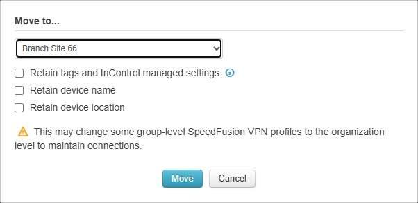
Move to... with a target group selected. The three Retain checkboxes are above the warning about group level SpeedFusion VPN profiles, and the button is Move.
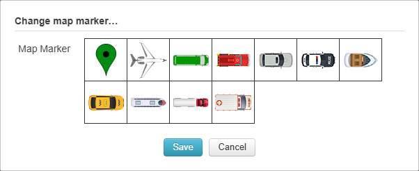
Change map marker... A grid of marker icons with Save and Cancel below it.
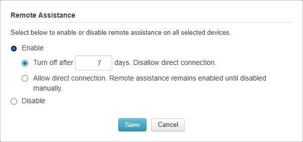
Remote Assistance with Enable selected. Below it, Turn off after a number of days (7 here) disallows direct connection, and Allow direct connection is the alternative.
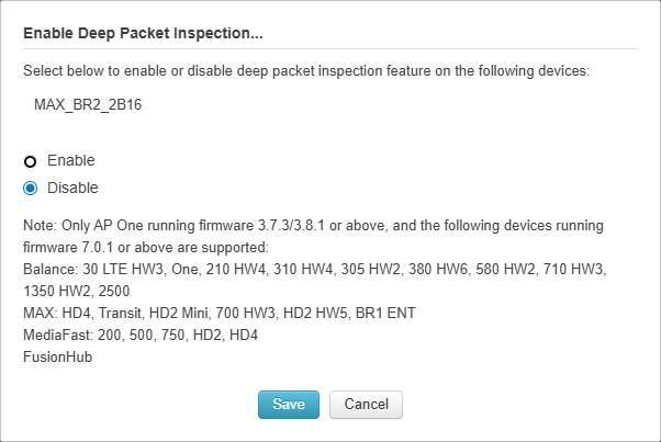
Enable Deep Packet Inspection. The form names the selected device, and its note lists the supported models and firmware.
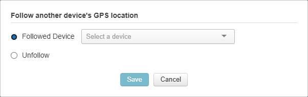
Follow another device's GPS location. Followed Device takes a device from the dropdown, and Unfollow is the other choice.
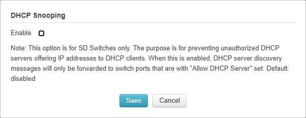
DHCP Snooping. A single Enable checkbox, with a note stating that it is for SD Switches only and disabled by default.
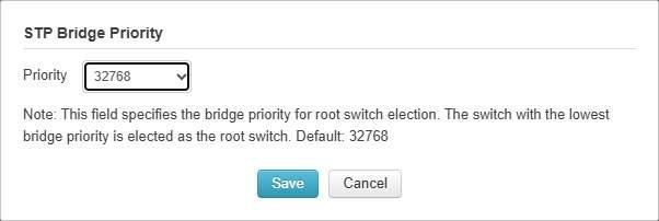
STP Bridge Priority showing the default value, 32768. The note states that the switch with the lowest bridge priority is elected root switch.
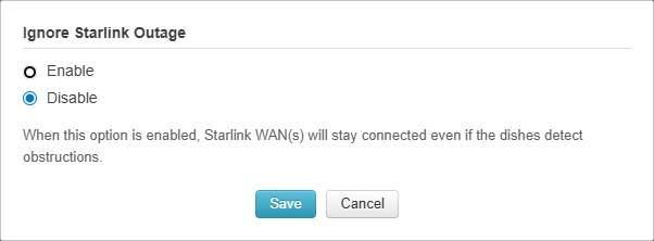
Ignore Starlink Outage with Disable selected. The note states that with Enable, Starlink WANs stay connected even if the Starlinks detect obstructions.
This menu has no reboot entry. Reboot a single device from Device > Settings > Device Tools (16.4 Device Tools), or set a reboot schedule under Scheduled Reboot on Device System Management (13.4.8 Scheduled Reboot). Download diagnostic reports... is the bulk equivalent of Diagnostic Report on Device Details (14.1.7 Diagnostic Report).
13.1.8. The Menu Changes with the Device You Selected
Entries that do not apply to the selected device are greyed rather than hidden. A greyed entry means the action does not apply to that device. This is expected and does not indicate a fault.
The list is the same for every device. Only the set of available entries changes. For a router and a switch in the same group:
Entry | Router | Switch |
Wi-Fi AP state... | Live | Greyed |
Enable DPI... | Live | Greyed |
Download diagnostic reports... | Live | Greyed |
Enable collecting Wi-Fi analytics data... | Live | Greyed |
Lock cellular WANs to current active SIM cards... | Live | Greyed |
eSIM Installation... | Live | Greyed |
Data roaming... | Live | Greyed |
Update cellular module firmware... | Live | Greyed |
Ignore Starlink Outage | Live | Greyed |
DHCP snooping | Greyed | Live |
STP bridge priority | Greyed | Live |
All other entries are live for both: Move to..., Remove..., Change map marker…, Firmware..., Top Up SFC Usage Plan..., Peplink eSIM Data..., Remote assistance..., Hardware watchdog..., Follow another device's GPS location..., Restore to factory defaults... and Create per-device custom SIM pools.... Three are greyed for both a router and a switch and require a device that supports them: Find My Peplink..., AP routing mode... and Enable Air Monitor mode....
Note the following:
- The switch entries appear only when the group contains a switch. A group of routers only does not list DHCP snooping or STP bridge priority.
- A mixed selection widens the menu. With devices of different types selected together, an entry is live when any selected device supports it. When an action is specific to one device type, select by device type, and check the Selected N devices: line before clicking.
13.1.9. eSIM Installation
The form asks questions rather than presenting settings, and the second question depends on the answer to the first. For installation on one device, and the requirements of each installation method, see How to install an eSIM in the Device Level Tools chapter (16.4.8 How to Install an eSIM).
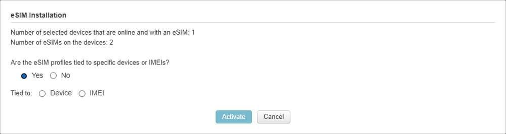
eSIM Installation. Selecting Yes adds a second question, Tied to, with Device or IMEI.
The form opens with two counts and one question:
Line | Meaning |
Number of selected devices that are online and with an eSIM | How many of the selected devices the action can reach |
Number of eSIMs on the devices | Total eSIM profiles across those devices |
Are the eSIM profiles tied to specific devices or IMEIs? | Yes or No |
The answer determines the next question:
- Yes adds a Tied to question, with Device or IMEI.
- No asks which cellular WAN to use, Cellular WAN 1 or Cellular WAN 2.
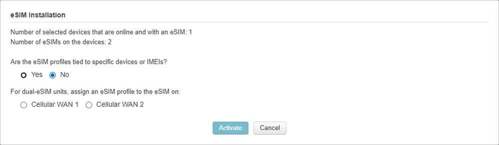
eSIM Installation with No selected. The form asks which eSIM on a dual eSIM unit receives the profile: Cellular WAN 1 or Cellular WAN 2.
The button is Activate. Nothing is activated until it is clicked.
13.1.10. Create Per-device Custom SIM Pools
Creates one custom pool for each selected device that has SIM cards attached, named with the Pool Name Prefix followed by the device name. The form has sixteen controls, six of which reveal further fields.
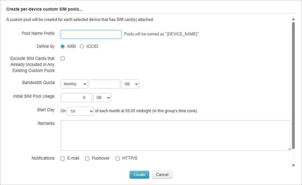
Create per-device custom SIM pools in its default state. Each notification checkbox at the bottom reveals its own block of fields.
Control | Values |
Pool Name Prefix | Free text, placed before the device name |
Define by | IMSI or ICCID |
Exclude SIM Cards that Already Included in Any Existing Custom Pools | Checkbox |
Bandwidth Quota | Daily, Weekly, Monthly or Yearly, with a figure and MB, GB or TB |
Initial SIM Pool Usage | A figure with MB or GB, for a pool that starts partway through its cycle |
Start Day | 1st to 28th, plus Last day, so the cycle start is valid in every month |
Remarks | Free text |
Stop Routing User Traffic | Checkbox, applied when the quota is exceeded. Bandwidth Throttling is the alternative and requires firmware 8.5.3 or newer. Earlier firmware uses Stop Routing User Traffic instead |
Bandwidth Throttling | Checkbox |
Six settings reveal further fields:
Set this | And this appears |
Bandwidth Quota to Weekly | Start Weekday, Sunday to Saturday |
Bandwidth Quota to Yearly | Start Date, as a month and a day |
Bandwidth Throttling | When Bandwidth Quota Exceeded, for the throttled rate |
HTTP/S | HTTP/S Notification URL |
Pushover | Pushover Application/API Token and Pushover user/group key(s) |
Eighteen further controls, described below |
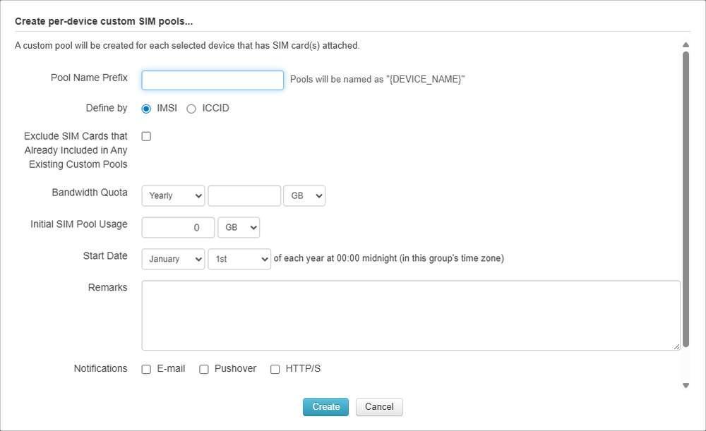
Bandwidth Quota set to Yearly. The Start Date row takes a month and a day.
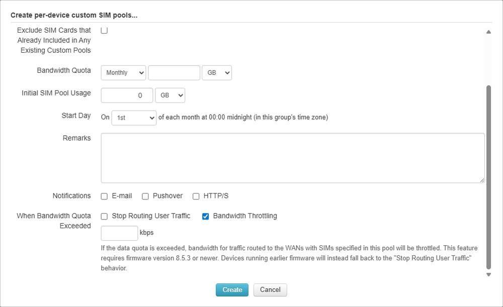
Bandwidth Throttling selected. A kbps field appears below it, with a note that this requires firmware 8.5.3 or newer and that earlier firmware uses Stop Routing User Traffic instead.
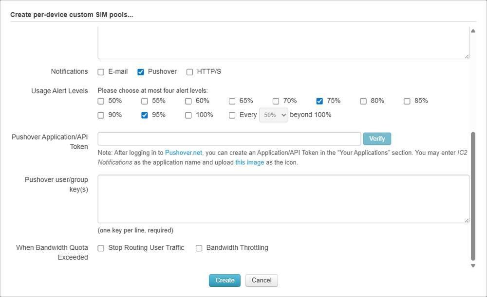
Pushover selected. The alert levels appear, followed by the Pushover Application/API Token field with its Verify button and the user or group key box, one key per line.
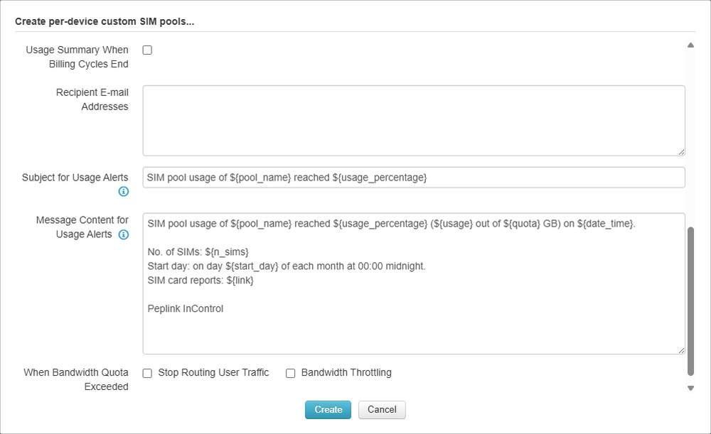
E-mail selected. The full set of alert levels, a beyond 100% option, a billing cycle summary, and the recipient, subject and message fields.
The E-mail block contains:
- Alert levels as eleven independent checkboxes, from 50% to 100% in steps of five.
- Every 50% / 100% beyond 100%, a checkbox with its own step choice, for pools expected to exceed their quota.
- Usage Summary When Billing Cycles End, a separate checkbox.
- Recipient E-mail Addresses, Subject for Usage Alerts and Message Content for Usage Alerts.
The button is Create.
Note the following:
- The alert levels are independent checkboxes, not a single threshold. A pool can alert at 80% and at 100% only.
- Initial SIM Pool Usage lets a pool created partway through a cycle start from the usage already consumed rather than from zero.
13.1.11. Update Device Info by CSV File
Renames devices or sets their site addresses in bulk.
Update device info by CSV file is a link under the device table, beside Download as CSV. It is not in the Actions menu. It opens a dialog with a drop zone, Drop CSV file here to upload (or Click), and a single Done button.
The dialog sets these rules for the file:
- The file contains either two fields, "SN", "Name", or five fields, "SN", "Name", "Address", "Latitude", "Longitude".
- The first line must be a field header.
- Every value is required except latitude and longitude. When those are empty, they are looked up from the address.
- Uploaded addresses, latitudes and longitudes overwrite each device's static location.
- A device that reports its own GPS location ignores the static location.
Caution: An upload with the five field layout replaces the static location of every device listed in the file. Download the device list with Download as CSV first, so the previous names and locations can be restored.
13.1.12. Checking the Fleet After a Change
- 1.Save the group level change on its own screen.
- 2.Open Group > Settings > Device Management.
- 3.Check Last Config Applied for each device. A value that has not changed since the save indicates a device that has not received the change.
- 4.Check the Status column for the four configuration state icons listed under Status icons: Config patches available, Configuration to device stopped. Configuration rolled back., InControl stopped to apply configurations to device. and Device disabled configurations from InControl. Each indicates a device that has not received the change.
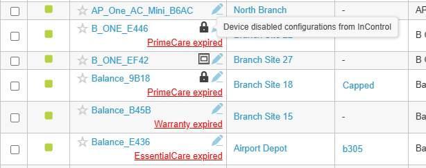
Step 4. A lock icon beside a device name. Its tooltip reads Device disabled configurations from InControl. The organization level grid is shown; the group level grid uses the same icons.
- 5.Click Download as CSV to save a copy of the grid.

Step 5. Download as CSV, outlined in red, below the Devices grid beside Update device info by CSV file.
13.2. Add Devices (Group Level)
Adds devices to the group by serial number, with optional tagging in the same step. The page states: Please ensure you own the devices and they are not managed by any other organizations. A device held by another organization cannot be added here.
Where to find it
Group > Settings > Add Devices
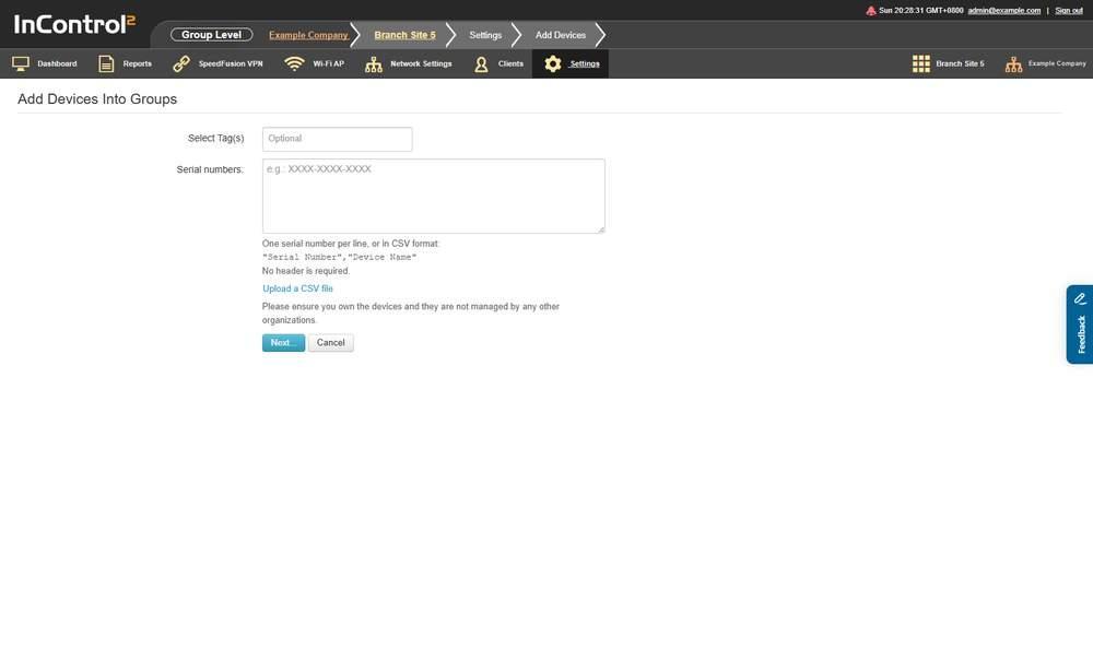
The serial number box accepts one serial number per line. The Select Tag(s) field above it is optional.
13.2.1. What This Screen Shows
The page contains one form, Add Devices Into Groups.
Field | Notes |
Select Tag(s) | Optional. Tags to apply to the devices being added. Tag-based Device Selection rules elsewhere in this chapter, such as Logging, SNMP, NetFlow and Notifications, then match the new devices without separate tagging through the Tag menu on Device Management (13.1.5 The Tag Menu) |
Serial numbers | One serial number per line, or in CSV format "Serial Number","Device Name". No header row is required. The box shows the placeholder e.g.: XXXX-XXXX-XXXX. The CSV format includes an optional device name, so devices can be named as they are added |
13.2.2. Controls on This Screen
Control | What it does |
Upload a CSV file | Supplies the serial numbers from a file. It remains on the form at every step of the wizard |
Next... | Continues to the next step of the wizard |
Cancel | Cancels the addition |
13.2.3. What Next... Does
Next... continues the wizard on the same page. Upload a CSV file, Next... and Cancel remain at each step.
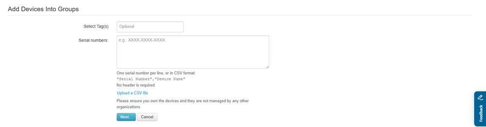
The first step. Select Tag(s), the serial number box, and the three controls that remain throughout the wizard: Upload a CSV file, Next... and Cancel.
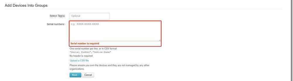
The result of Next... with the serial number box empty. The box, outlined in red, shows the message Serial number is required, and the rest of the form is unchanged.
At least one serial number is required before the wizard continues.
13.3. Device IP Settings
Imports LAN and VLAN IP settings for many devices at once from CSV text, and lists the field names the CSV must use. The two field tables are reference text on the page, not editable grids.
Where to find it
Group > Settings > Device IP Settings
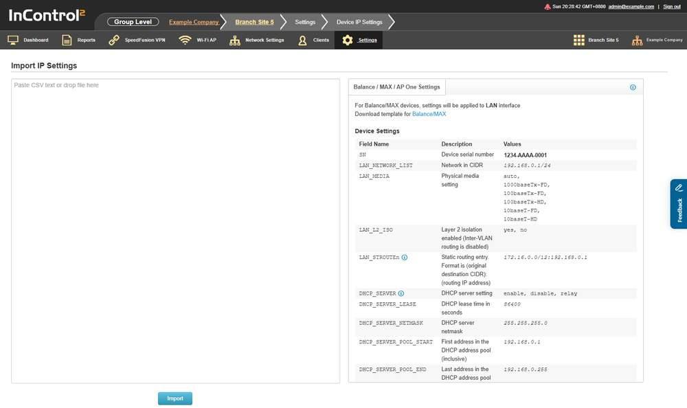
The import box at the top accepts pasted CSV text or a dropped file. The two reference tables below it list every field name the CSV may contain.
13.3.1. The Import Box
The screen opens on a single tab, Balance / MAX / AP One Settings.
Control | What it does |
Paste CSV text or drop file here | Accepts the settings as pasted text or as a dropped file |
Import | Applies the pasted or dropped settings |
Download template for Balance/MAX | Downloads a CSV template for Balance and MAX devices |
Balance / MAX / AP One Settings | The tab containing the instructions and field reference shown here |
The page states that for Balance and MAX devices the settings are applied to the LAN interface.
A separate link on this screen has the tooltip Click here for legacy AP One devices' IP settings. Legacy AP One units are configured there rather than through this field set.
13.3.2. Device Settings Field Reference
The Device Settings table lists the field names that apply to the device itself.
Field Name | Description | Values |
SN | Device serial number. The only field that identifies the device, so every row must contain a correct serial number | 1234-AAAA-0001 |
LAN_NETWORK_LIST | Network in CIDR | 192.168.0.1/24 |
LAN_MEDIA | Physical media setting | auto, 1000baseTx-FD, 100baseTx-FD, 100baseTx-HD, 10baseT-FD, 10baseT-HD |
LAN_L2_ISO | Layer 2 isolation enabled (Inter-VLAN routing is disabled) | yes, no |
LAN_STROUTEn | Static routing entry. Format is (original destination CIDR):(routing IP address) | 172.16.0.0/12:192.168.0.1 |
DHCP_SERVER | DHCP server setting | enable, disable, relay |
DHCP_SERVER_LEASE | DHCP lease time in seconds | 86400 |
DHCP_SERVER_NETMASK | DHCP server netmask | 255.255.255.0 |
DHCP_SERVER_POOL_START | First address in the DHCP address pool (inclusive) | 192.168.0.1 |
DHCP_SERVER_POOL_END | Last address in the DHCP address pool (inclusive) | 192.168.0.255 |
DHCP_RESERVATION | DHCP reserved addresses | 00:00:00:00:00:01#192.168.0.10#optional-name-field |
DHCP_LOG_ENABLE | DHCP logging enabled | yes, no |
DHCP_SERVER_DNS | DNS primary and (optional) secondary addresses | 192.168.0.1 192.168.0.2 |
DHCP_SERVER_WINS | WINS primary and (optional) secondary addresses | 192.168.0.1 192.168.0.2, default |
DHCP_OPTION_15 | DHCP Option 15 domain name | example.com |
DHCP_RELAY_OPTION_82 | DHCP Option 82 (52 hex) enabled | yes, no |
DHCP_RELAY_SERVER | DHCP primary and (optional) secondary relay addresses | 192.168.0.1 192.168.0.2 |
13.3.3. Which Fields Are Required
Several rows in the table have an information icon. Their tooltips state which fields are required.
DHCP_SERVER determines which other fields are required:
DHCP_SERVER set to | Required alongside it | Optional alongside it |
enable | DHCP_SERVER_LEASE, DHCP_SERVER_NETMASK, DHCP_SERVER_POOL_START, DHCP_SERVER_POOL_END, DHCP_LOG_ENABLE | DHCP_RESERVATION, DHCP_SERVER_DNS, DHCP_SERVER_WINS, DHCP_OPTION_15 |
relay | DHCP_RELAY_OPTION_82, DHCP_RELAY_SERVER, DHCP_LOG_ENABLE | |
disable | No DHCP_SERVER_* fields are required |
Any DHCP_SERVER_* field that is not specified is ignored.
DHCPn_SERVER follows the same rule for the VLAN fields, using the n prefixed names, and ignores unspecified DHCPn_SERVER_* fields in the same way.
LAN_STROUTEn is optional. The tooltip states it may be left blank or the column omitted, and that multiple static routes are defined by incrementing the route number, for example LAN_STROUTE1 and LAN_STROUTE2.
AP_IP_ADDR_MODE sets the address type of an AP and takes static or dhcp. Its tooltip states that with static the fields AP_IP_ADDR, AP_LAN_SUBNETMASK, AP_GATEWAY and AP_DNS are required, and that with dhcp those four fields are ignored.
DHCP_RESERVATION is optional and takes a space separated list. Each entry has the format [MAC address]#[IP address]#[optional name]. The name field supports ASCII alphanumeric characters, _ and - only. Do not use any other character, including a space.
13.3.4. VLAN Settings Field Reference
The VLAN Settings table lists the same settings per VLAN. The n in each field name is the VLAN index. VLAN entries are optional. Multiple VLANs are defined by incrementing the LAN and DHCP number, for example LAN1_VLAN_ID, LAN1_NAME through to LAN5_VLAN_ID, LAN5_NAME.
Field Name | Description | Values |
LANn_VLAN_ID | ID of the VLAN | 1-4094 |
LANn_NAME | Name of the VLAN | "VLAN 1", "Marketing Network", etc |
LANn_NETWORK_LIST | Network in CIDR | 192.168.0.1/24 |
LANn_L2_ISO | Layer 2 isolation enabled (Inter-VLAN routing is disabled) | yes, no |
DHCPn_SERVER | DHCP server setting | enable, disable, relay |
DHCPn_SERVER_LEASE | DHCP lease time in seconds | 86400 |
DHCPn_SERVER_NETMASK | DHCP server netmask | 255.255.255.0 |
DHCPn_SERVER_POOL_START | First address in the DHCP address pool (inclusive) | 192.168.0.1 |
DHCPn_SERVER_POOL_END | Last address in the DHCP address pool (inclusive) | 192.168.0.255 |
DHCPn_RESERVATION | DHCP reserved addresses | 00:00:00:00:00:01#192.168.0.10#optional-name-field |
DHCPn_LOG_ENABLE | DHCP logging enabled | yes, no |
DHCPn_SERVER_DNS | DNS primary and (optional) secondary addresses | 192.168.0.1 192.168.0.2 |
DHCPn_SERVER_WINS | WINS primary and (optional) secondary addresses | 192.168.0.1 192.168.0.2, default |
DHCPn_OPTION_15 | DHCP Option 15 domain name | example.com |
DHCPn_RELAY_OPTION_82 | DHCP Option 82 (52 hex) enabled | yes, no |
DHCPn_RELAY_SERVER | DHCP primary and (optional) secondary relay addresses | 192.168.0.1 192.168.0.2 |
Caution: VLANs imported here are applied to the devices only. The tooltip on the VLAN reference states that they are not imported to the VLAN Networks page on InControl 2. Create them on the VLAN Networks page as well to keep the two consistent.
13.4. Device System Management
Manages the device-level system settings for the whole group, section by section, including event, SNMP and flow record export, and configures redirection to an external InControl Appliance. The Bulk Configurator rules (13.12.1 What the Page Tells You First) list Web Admin Settings and Time zone among the settings InControl 2 manages. Where InControl 2 manages them, a change made on the device is overwritten, so make lasting changes here.
Where to find it
Group > Settings > Device System Management
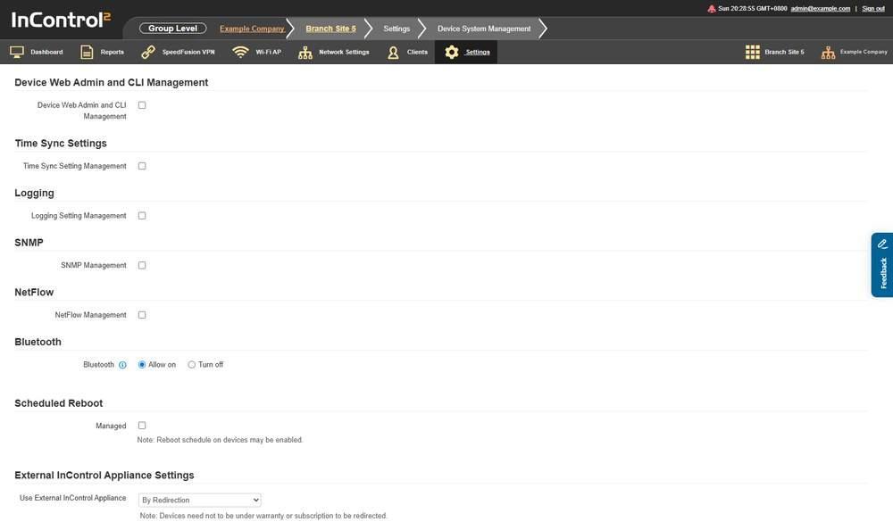
Each section has its own management checkbox. A section's settings are configurable at group level only after its checkbox is selected.
13.4.1. The Section Gates
The screen is divided into sections, and most have their own management checkbox. Until a section's checkbox is selected, InControl 2 does not manage that setting at group level and the section's settings are hidden. Every section is gated except Bluetooth and External InControl Appliance Settings. Selecting a gate is itself a change: the section is managed at group level as soon as the changes are saved. Before selecting the gate, read 8.1.1 Before You Tick a Manage Checkbox.
Section | Gate checkbox |
Device Web Admin and CLI Management | Device Web Admin and CLI Management |
Time Sync Settings | Time Sync Setting Management |
Logging | Logging Setting Management |
SNMP | SNMP Management |
NetFlow | NetFlow Management |
Scheduled Reboot | Managed |
Below Scheduled Reboot the page states: Note: Reboot schedule on devices may be enabled. With the group level gate off, a reboot schedule may still be running on the devices themselves.
Most gated sections have their own Device Selection list, so each targets its own subset of the group. Logging, SNMP and NetFlow each have one, Device Web Admin and CLI Management has one under General, and Scheduled Reboot sets Device Selection per instruction. Time Sync Settings has no Device Selection list.
13.4.2. Device Web Admin and CLI Management
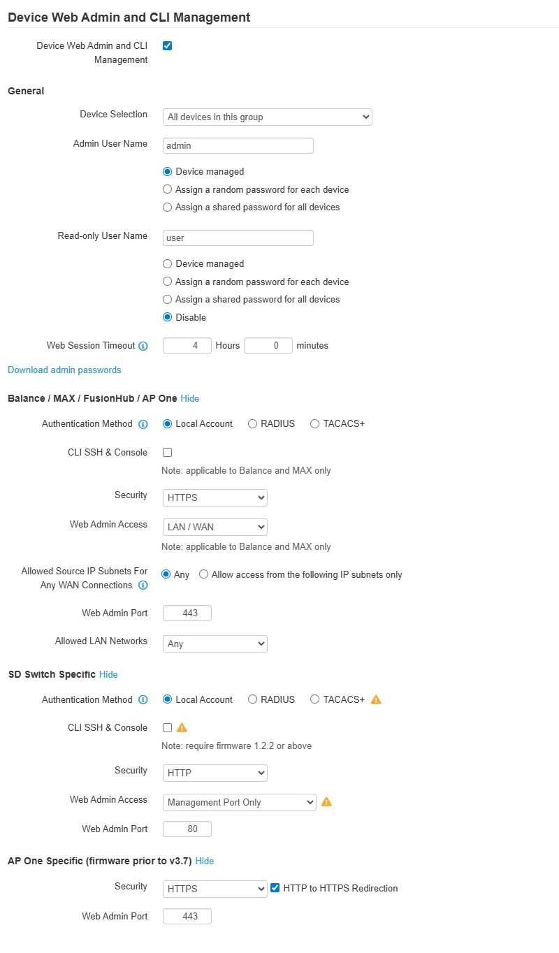
The section with its gate selected. General is followed by separate blocks for Balance / MAX / FusionHub / AP One, SD Switch Specific and AP One Specific.
Setting | What the interface states |
Web Session Timeout | Given in hours and minutes. A web login session is logged out automatically after it has been idle longer than this. Default: 4 hours 0 minutes |
Authentication Method | Local Account, RADIUS, TACACS+ |
NAS-Identifier | Option list beginning None, Device Name, LAN MAC Address, Device Serial Number. Require firmware 8.6.0 or above. |
Primary Server, Secondary Server | The authentication servers. Require firmware 8.5.3 or above. |
Source Network Address | A VLAN network or Untagged LAN. Note: Untagged LAN will be applied if a device does not have the selected VLAN Network defined. |
Allowed Source IP Subnets For Any WAN Connections | Any, or Allow access from the following IP subnets only |
Three of these settings carry warnings.
Web Session Timeout accepts 0 hours 0 minutes, which means an unlimited session time. InControl 2 states that this should be used only in special situations, as it lowers the system security level if users do not log out before closing the browser. Clicking Logout in the web admin ends a session before it expires.
Authentication Method determines which accounts are active. With an external method selected, the web admin authenticates against that service and the local admin and user accounts are disabled. If the device cannot reach the external service, the local accounts are enabled again for emergency access, so a RADIUS or TACACS+ outage does not lock the device out permanently. TACACS+ support is available on all products except Balance/MAX and AP One with firmware below 8.1.0 and 3.8.1 respectively.
Allowed Source IP Subnets For Any WAN Connections restricts web admin access from WAN connections to the listed subnets.
- Any allows web admin access from anywhere with no IP address restriction.
- Allow access from the following IP subnets only restricts access to the subnets defined.
- Each subnet is written as w.x.y.z/m, where w.x.y.z is an IP address and m is the subnet mask in CIDR format, between 0 and 32 inclusive, for example 192.168.0.0/24.
- Enter multiple subnets one per line.
- On Balance and MAX the restriction applies only when LAN / WAN is selected in the Web Admin Access field above it. Set that field first.
13.4.3. Time Sync Settings
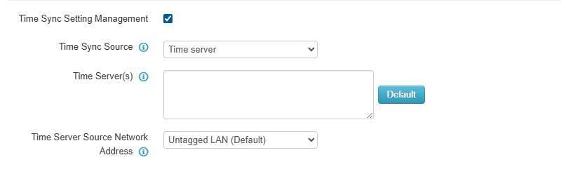
Time Sync Setting Management selected. Time Sync Source, Time Server(s) with its Default button, and Time Server Source Network Address appear below it.
Setting | Options and notes |
Time Sync Source | Time server, GPS, GPS with Time Server as fallback. On unsupported devices only time servers are used as the source |
Time Server(s) | The time servers to use, with a Default option. On unsupported devices only the first time server is used |
Time Server Source Network Address | A VLAN network or the untagged LAN. If the selected VLAN network is unavailable, the untagged LAN is used |
The two unsupported device notes are stated in the tooltips. On devices that do not support GPS time sync, a group set to GPS uses time servers, and only the first entry of a time server list is used.
13.4.4. Logging
Selecting Logging Setting Management reveals a logging profile on its own tab, Profile 1.
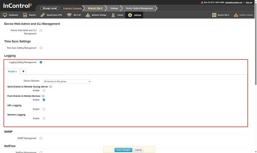
Logging Setting Management selected. The checkbox and the Profile 1 tab it reveals are outlined in red. The four logging destinations each appear as a single Enable checkbox under the profile's Device Selection list.
Setting | Notes |
Device Selection | All devices in this group, Devices with any of the following tags, Devices with all of the following tags, Devices with none of the following tags |
Send Events to Remote Syslog Server | Enable checkbox |
Push Events to Mobile Devices | Enable checkbox |
URL Logging | Enable checkbox |
Session Logging | Enable checkbox |
The four checkboxes are independent. The Device Selection list applies to the profile rather than to the section as a whole.
13.4.5. SNMP
Selecting SNMP Management reveals the SNMP service settings and two credential lists.
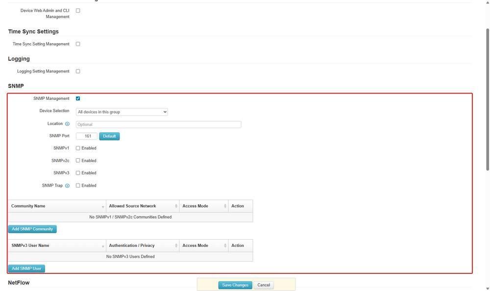
SNMP Management selected. The checkbox and the settings it reveals, including the two credential lists, are outlined in red. The lists define the communities and users permitted to use each enabled version.
Setting | Notes |
Device Selection | All devices in this group plus the three tag-based choices |
Location | The DisplayString value of sysLocation. Not applicable to AP One running firmware prior to 3.7 |
SNMP Port | The port SNMP listens on, with a Default option |
SNMPv1 Enabled | Checkbox |
SNMPv2c Enabled | Checkbox |
SNMPv3 Enabled | Checkbox |
SNMP Trap Enabled | Checkbox. Not applicable to AP One running firmware prior to 3.7 |
Two lists are below these settings.
SNMPv1 and SNMPv2c communities, with columns Community Name, Allowed Source Network, Access Mode and Action. When empty it reads No SNMPv1 / SNMPv2c Communities Defined. Add SNMP Community adds an entry.
SNMPv3 users, with columns User Name, Authentication / Privacy, Access Mode and Action. When empty it reads No SNMPv3 Users Defined. Add SNMP User adds an entry.
Enabling a version does not create a credential. Selecting SNMPv3 Enabled does not create an SNMPv3 user, so add the matching entry in the list below before polling the device.
13.4.6. NetFlow
Selecting NetFlow Management reveals the flow export settings.
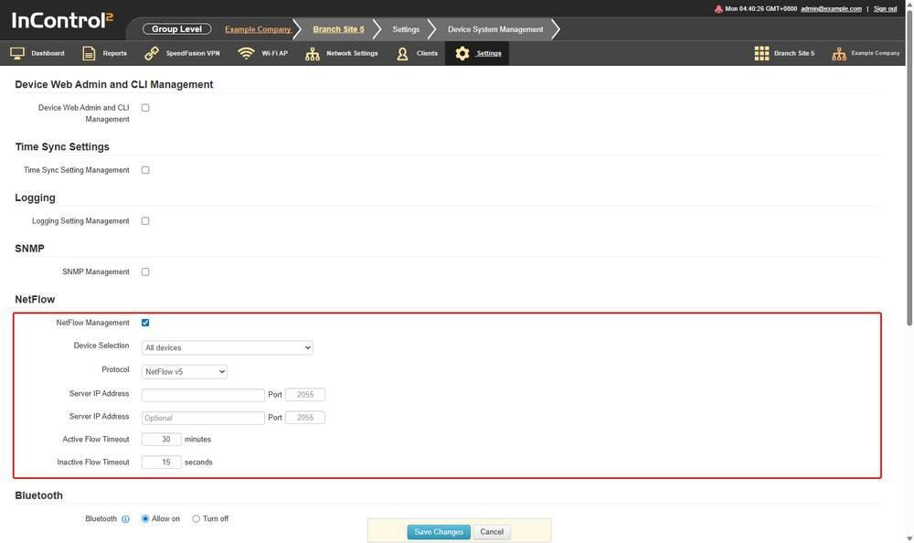
NetFlow Management selected. The checkbox and the fields it reveals are outlined in red. There are two collector rows, and the two timeouts use different units.
Setting | Notes |
Device Selection | All devices plus the three tag-based choices |
Protocol | NetFlow v5, NetFlow v9, IPFIX |
Server | Collector IP Address and Port. Two server rows are available |
Active Flow Timeout | A number, in minutes |
Inactive Flow Timeout | A number, in seconds |
The two timeouts use different units: Active Flow Timeout is in minutes and Inactive Flow Timeout in seconds.
13.4.7. Bluetooth
Bluetooth is not gated. The tooltip on the setting describes each option.

The Bluetooth section with Allow on selected. It has no management checkbox.
Option | Effect |
Allow on | Bluetooth on all devices in the group can be turned on or off in the Peplink app or on the web admin |
Turn off | Bluetooth on all devices in the group is unconditionally turned off |
Allow on permits Bluetooth to be switched on at the device. It does not switch it on.
13.4.8. Scheduled Reboot
Selecting Managed reveals a list of schedule instructions.
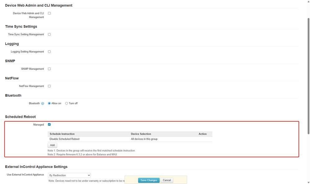
Managed selected. The checkbox and the Schedule Instruction list it reveals are outlined in red. Each entry pairs an instruction with a device selection, and Add appends another.
The list has the columns Schedule Instruction, Device Selection and Action. The first entry shows the instruction Disable Scheduled Reboot with the device selection All devices in this group. Add appends another instruction.
Two notes are below the list:
- Note 1: Devices in the group will receive the first matched schedule instruction.
- Note 2: Require firmware 6.3.2 or above for Balance and MAX
Under Note 1, a device selected by two instructions takes the first that matches it. Order the list from the most specific selection to the most general.
13.4.9. External InControl Appliance Settings
Directs the group's devices to a customer operated InControl Appliance instead of the hosted service.
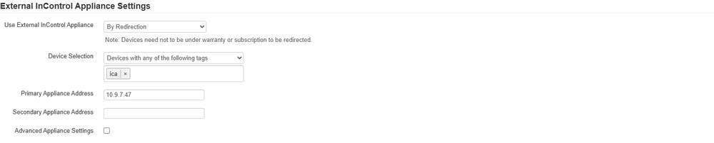
By Redirection selected, with Device Selection set to devices with a tag and a Primary Appliance Address entered. The note below the first field applies to this mode.
Field | Options or notes |
Use External InControl Appliance | Disabled, By Redirection, By Configuration |
Device Selection | All devices, Devices with any of the following tags, Devices with all of the following tags, Devices with none of the following tags |
Tags | Free text tag entry, used with the three tag-based Device Selection options. Each entered tag has a × to remove it |
Primary Appliance Address | Address of the appliance |
Secondary Appliance Address | Optional second address |
Advanced Appliance Settings | Checkbox that reveals two further fields, described below |
With Use External InControl Appliance set to Disabled or By Redirection the page states: Note: Devices need not to be under warranty or subscription to be redirected.
13.4.10. What Changes When By Configuration Is Chosen
Selecting By Configuration changes the screen in two ways.
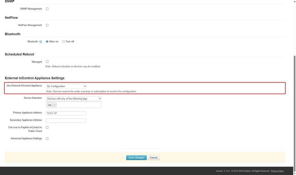
By Configuration selected. The field and the note below it, outlined in red, now require warranty or subscription, and a Fail over to Peplink InControl in Public Cloud checkbox appears lower in the block.
Change | Detail |
The note is replaced | It becomes Note: Devices need to be under warranty or subscription to receive the configuration. |
A new checkbox appears | Fail over to Peplink InControl in Public Cloud |
Redirection reaches devices with no active warranty or subscription. Configuration does not.
Caution: Confirm which mode your appliance deployment expects before saving. By Redirection and By Configuration apply to every device the Device Selection rule matches. The warranty note reverses between the two, and By Configuration adds the Fail over to Peplink InControl in Public Cloud checkbox. For help choosing a mode, contact Peplink support or your Peplink partner.
13.4.11. Advanced Appliance Settings
Selecting Advanced Appliance Settings reveals two fields.
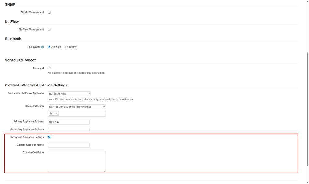
Advanced Appliance Settings selected. The checkbox and the two fields it reveals, outlined in red, are at the bottom of the appliance block.
Field | Notes |
Custom Common Name | A single line text field |
Custom Certificate | A text area for the full certificate |
Take the values for both fields from your InControl Appliance deployment.
13.4.12. Controls on This Screen
Control | What it does |
Save Changes | Saves the changes. Disabled until something is changed |
Cancel | Discards the changes |
13.5. Certificate Management (Group Level)
Holds the private keys and certificates that InControl 2 pushes to each device in the group, organized by certificate purpose.
Where to find it
Group > Settings > Certificate Management
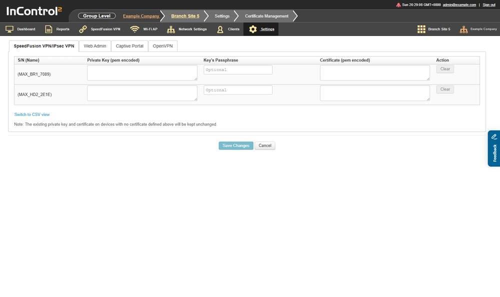
One row per device, with the certificate tabs across the top. The SpeedFusion VPN/IPsec VPN tab is shown.
13.5.1. Tabs
The page has four tabs.
Tab | Purpose |
SpeedFusion VPN/IPsec VPN | Certificates for SpeedFusion VPN and IPsec VPN. This tab opens first |
Web Admin | Certificates for the device web admin interface |
Captive Portal | Certificates for the captive portal. This tab is a profile editor, not the device grid, so the columns and controls described below do not apply to it |
OpenVPN | Certificates for OpenVPN |
13.5.2. What This Screen Shows
One row per device. The devices listed depend on the tab, and the three grid tabs do not list the same devices. For example, Web Admin can include FusionHub and switches, while OpenVPN lists no access points.
Caution: Check which tab is selected before pasting a key into a row. A device listed on one tab may not appear on another.
Column | What it shows |
S/N (Name) | Device serial number, with the device name in brackets |
Private Key (pem encoded) | Text area for the PEM encoded private key |
Key's Passphrase | Passphrase for the key. Marked Optional |
Certificate (pem encoded) | Text area for the PEM encoded certificate |
Action | The per row Clear button |
The page states: Note: The existing private key and certificate on devices with no certificate defined above will be kept unchanged. A blank row does not remove the existing certificate from that device.
13.5.3. Controls on This Screen
Control | What it does |
Clear | Clears the certificate entry for that row. Disabled while the row is empty |
Switch to CSV view | Switches the grid to a CSV representation |
Save Changes | Saves the changes. Disabled until something is changed |
Cancel | Discards the changes |
13.5.4. What Differs Between the Tabs
The SpeedFusion VPN/IPsec VPN, Web Admin and OpenVPN tabs share the columns and controls above, and each shows the note about devices with no certificate defined. Two tabs add their own items.
Web Admin is the only tab whose Action column offers more than Clear.

The Web Admin tab. In the Action column the first device row shows a selected Auto Set Up checkbox with an information icon, and the second row shows Clear.
What it adds | Detail |
Auto Set Up in the Action column | A checkbox labelled Auto Set Up, with an information icon, shown on some device rows in place of Clear |
OpenVPN adds a firmware requirement.
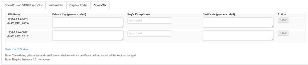
The OpenVPN tab. Below the note about undefined certificates is a second note, Require firmware 8.3.1 or above.
Below the first note the tab states: Note: Require firmware 8.3.1 or above. Devices on older firmware do not accept an OpenVPN certificate from this tab.
13.6. InControl Options
Controls the extent to which InControl 2 manages the devices in the group, how quickly a device that stops communicating is marked offline, and how much data is consumed by management traffic.
Where to find it
Group > Settings > InControl Options
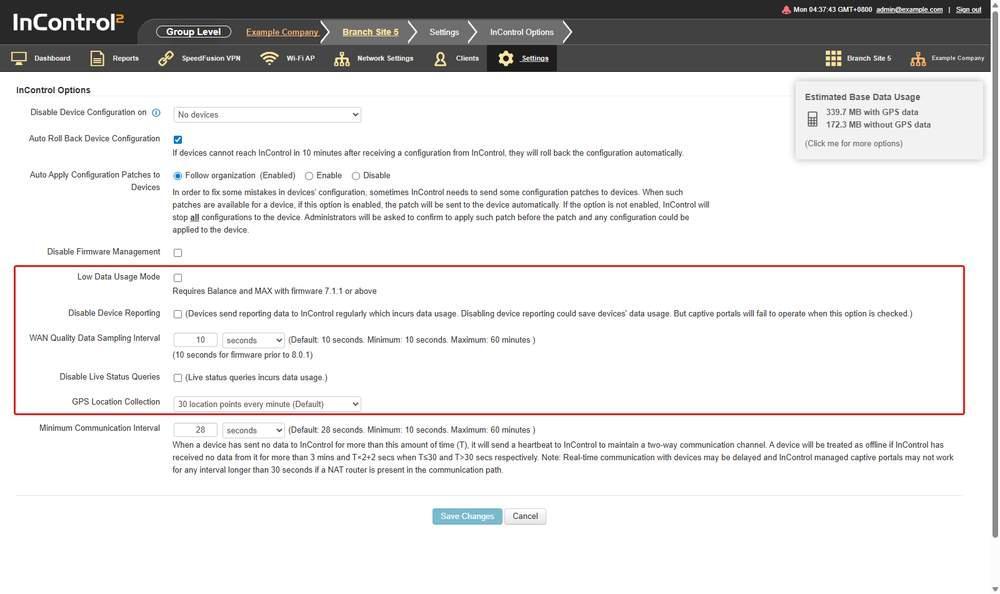
The Low Data Usage Mode block, outlined in red, contains the checkbox and the four settings below it that reduce management traffic.
13.6.1. Configuration Control
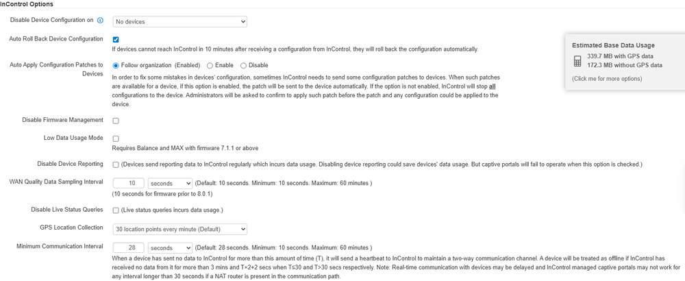
The InControl Options block. The four configuration control settings are at the top, and the Estimated Base Data Usage panel is to the right.
Setting | Options and notes |
Disable Device Configuration on | No devices, All devices, Devices with any of the following tags, Devices with all of the following tags, Devices with none of the following tags. The tooltip states: InControl will not make any configuration changes to selected devices |
Auto Roll Back Device Configuration | Checkbox. The page states: If devices cannot reach InControl in 10 minutes after receiving a configuration from InControl, they will roll back the configuration automatically. Selected by default in a new group |
Auto Apply Configuration Patches to Devices | Follow organization (Enabled), Enable, Disable |
Disable Firmware Management | Checkbox |
The page states the effect of turning Auto Apply Configuration Patches to Devices off. If the option is not enabled, InControl 2 stops all configuration to the device, and an administrator must confirm the patch before that patch or any further configuration can be applied.
Two of these settings provide a change freeze and a safety net:
- To freeze configuration on selected sites, tag the devices and set Disable Device Configuration on to Devices with any of the following tags with that tag. InControl 2 makes no configuration changes to those devices until the selection is changed back.
- Auto Roll Back Device Configuration applies when a group change disconnects a device: a device that cannot reach InControl 2 within 10 minutes of receiving a configuration rolls it back. Devices whose configuration was rolled back show the Configuration to device stopped. Configuration rolled back. icon on Device Management (13.1.2 Status Icons).
13.6.2. Low Data Usage Mode
The page states that this block requires Balance and MAX with firmware 7.1.1 or above.
Setting | Options and notes |
Disable Device Reporting | Checkbox. The page warns that captive portals will fail to operate when this option is checked |
WAN Quality Data Sampling Interval | A number plus seconds or minutes. The page states: default 10 seconds, minimum 10 seconds, maximum 60 minutes, and 10 seconds for firmware prior to 8.0.1 |
Disable Live Status Queries | Checkbox. The page notes that live status queries incur data usage |
GPS Location Collection | 30 location points every minute (Default), 60 location points every hour, 1 location point every 30 minutes, 1 location point every hour, Disabled |
Disabling device reporting reduces data usage but also stops InControl 2 managed captive portals from working.
13.6.3. Minimum Communication Interval
This interval determines how quickly InControl 2 marks a device offline. At the default of 28 seconds, a device is treated as offline when InControl 2 has received nothing from it for more than 3 minutes. A longer interval reduces cellular data usage but lengthens this time: at 5 minutes, it becomes more than 10 minutes 2 seconds.
A number plus seconds or minutes. The page states: default 28 seconds, minimum 10 seconds, maximum 60 minutes.
The page states the offline rule. When a device has sent no data for longer than this interval (T), it sends a heartbeat. A device is treated as offline if InControl 2 has received no data from it for more than 3 minutes when T is 30 seconds or less, and for more than T×2+2 seconds when T is greater than 30 seconds.
The page also cautions that real-time communication with devices may be delayed and InControl 2 managed captive portals may not work for any interval longer than 30 seconds if a NAT router is present in the communication path.
13.6.4. The Base Data Usage Calculator
The Estimated Base Data Usage figure has the prompt (Click me for more options). It opens the Base Data Usage Calculator, which shows how the estimate is calculated.
The figure changes with the selected options, so it shows the data cost of a setting before saving. The figures shown in the screenshot are examples only. Values vary by group and period. The period the estimate covers is set in the Period field inside the calculator.
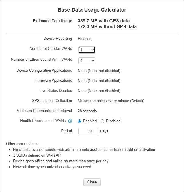
The calculator opened from the Estimated Base Data Usage figure. Only three rows are editable; the others show the settings the estimate is based on.
The estimate is shown twice at the top, with GPS data and without GPS data.
Three rows are editable in the dialog:
Field | Options |
Number of Cellular WANs | 0 through 21 |
Number of Ethernet and Wi-Fi WANs | 0 through 13 |
Period | A number, in Days |
The other rows show the settings the estimate is based on and are not editable: Device Reporting, Device Configuration Applications, Firmware Applications, Live Status Queries, GPS Location Collection, Minimum Communication Interval and Health Checks on all WANs.
Health Checks on all WANs shows Enabled or Disabled and reports the current state of the devices. Its tooltip states: Note: This field is not a setting. Please make health check changes over the web admin.
Device Configuration Applications, Firmware Applications and Live Status Queries each show their count followed by (Note: not disabled).
The dialog lists the assumptions behind the estimate:
- No clients, events, remote web admin, remote assistance, or feature add-on activation
- 3 SSIDs defined on Wi-Fi AP
- Device goes offline and online no more than once per day
- Network time synchronizations always succeed
Close closes the dialog. The calculator changes no settings.
13.7. Notifications
Defines who is notified about events in the group, through which channel, and for which devices. The page also carries a Suppressed E-mail Addresses heading. For help with a suppressed address, contact Peplink support or your Peplink partner.
Where to find it
Group > Settings > Notifications
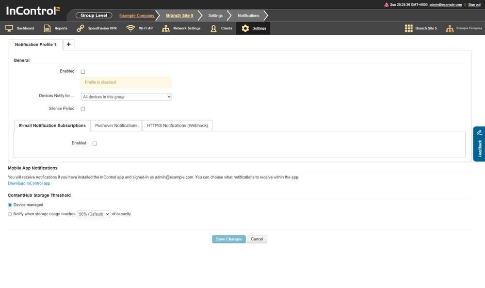
Notification Profile 1 is a profile tab. The three delivery channel tabs are lower down, inside the profile.
13.7.1. Notification Profiles
Profiles appear as tabs across the top, for example Notification Profile 1.
13.7.2. General

The General block with Enabled cleared. The page shows Profile is disabled. below the checkbox.
Setting | Options and notes |
Enabled | Checkbox. While it is cleared, the page states Profile is disabled. |
Devices Notify for ... | All devices in this group, Devices with any of the following tags, Devices with none of the following tags |
Silence Period | Checkbox. Reveals the quiet hours, described below |
To limit a profile to a subset of sites, tag those devices and set Devices Notify for ... to Devices with any of the following tags with that tag.
13.7.3. Silence Period
Selecting Silence Period reveals two time ranges by default, one for weekdays and one for the weekend.
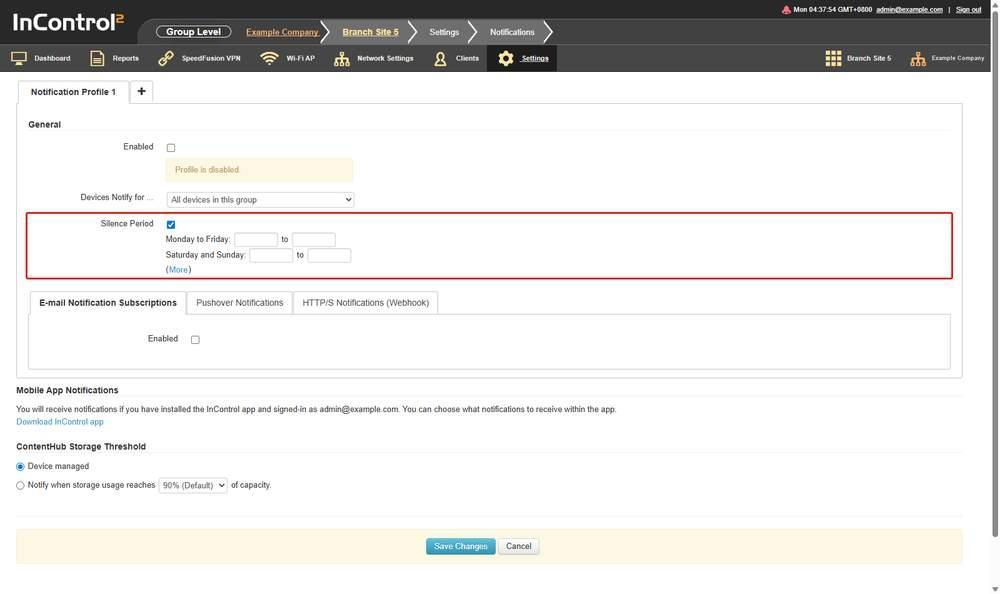
Silence Period selected. The checkbox and the time ranges it reveals are outlined in red. The weekday and weekend ranges each have their own start and end time.
Row | Fields |
Monday to Friday: | A start time and an end time |
Saturday and Sunday: | A start time and an end time |
- Weekday and weekend hours are independent. A weekday silence period does not apply to the weekend.
- A (More) link at the end of the block switches the Silence Period to separate start and end times for each day, Sunday to Saturday.
13.7.4. Delivery Channels
A profile sends alerts only when its own Enabled checkbox and the channel's gate are both on. Pushover has no enable control. Then select each event and, for e-mail, its recipients.
The profile has three tabs, one per delivery channel.
Tab | Purpose |
E-mail Notification Subscriptions | E-mail recipients and their subscriptions. This tab opens first |
Pushover Notifications | Notifications through Pushover |
HTTP/S Notifications (Webhook) | Notifications delivered to a webhook |
The profile's General block remains above the open channel tab. The Enabled, Devices Notify for ... and Silence Period settings belong to the profile, not to the channel. Each channel has its own gate: E-mail Notification Subscriptions has its own Enabled checkbox, the webhook tab is gated by the HTTP/S Notification URL checkbox, and Pushover Notifications has no enable control.
E-mail Notification Subscriptions
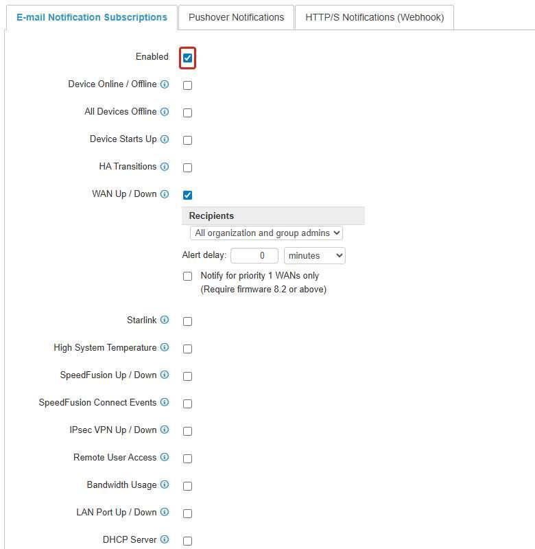
The e-mail channel with its Enabled checkbox selected, outlined in red. Each event type has its own checkbox, and a selected event such as WAN Up / Down shows its Recipients choice and extra options below it. The list continues below the visible area.
The tab has its own Enabled checkbox. When the channel is enabled, the tab lists every event type with a checkbox and a Recipients choice, so each event can go to different recipients. See Events you can be notified about below.
Recipients option | Who receives it |
All organization and group admins | Every administrator of the organization and of the group |
All group admins | Every administrator of this group |
An organization admin | One selected organization administrator |
A group admin | One selected group administrator |
Other e-mail addresses | Entered addresses, including people without an InControl 2 account |
Pushover Notifications

The Pushover channel. One token field with a Verify button beside it, and the note below describing how to obtain the token.
Control | Notes |
Pushover Application/API Token | Text field for the token |
Verify | Checks the token entered |
The tab describes the service: Pushover is a mobile app for receiving notifications with customizable sounds and alert levels.
The tab also states how to obtain the token: after signing in to Pushover.net, create an Application/API Token in the Your Applications section. The tab suggests IC2 Notifications as the application name and provides an image on the page to use as the icon. The token is created in Pushover and then pasted here. InControl 2 does not generate it.
HTTP/S Notifications (Webhook)
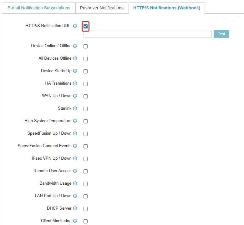
The webhook channel with the HTTP/S Notification URL checkbox selected, outlined in red. The address field and the Test button appear below it, followed by one checkbox per event type. The list continues below the visible area.
The tab has a checkbox labelled HTTP/S Notification URL, which enables the channel. When it is selected, the tab contains:
- an address field for the URL that receives the notifications
- a Test button, which reports Sent or Failed
- one checkbox per event type
The webhook offers two event types that e-mail and Pushover do not: Site Survey Report Updates and Connection Test Report Updates.
13.7.5. Events You Can Be Notified About
E-mail and Pushover offer the same 31 event types. The webhook offers those 31 plus the two report updates noted above.
Area | Event types |
Device state | Device Online / Offline, All Devices Offline, Device Starts Up, HA Transitions, High System Temperature |
WAN and VPN | WAN Up / Down, Starlink, SpeedFusion Up / Down, SpeedFusion Connect Events, IPsec VPN Up / Down, Remote User Access, Bandwidth Usage |
LAN and clients | LAN Port Up / Down, DHCP Server, Client Monitoring, AirProbe Alarms |
Configuration and firmware | Configuration Changes Applied, Configuration Rolled Back, Too Many Firmware Update Attempts, Web Admin Logins |
Cellular | SIM Card Switch Over, SIM Card Insertion / Removal, PLMN Switch Over |
Tests and storage | Connection Test Fails, ContentHub Storage Alarms |
Accessories and IoT | Smart Reader Attachment / Detachment, POTS and MAX Adapter Power Supply Changes, POTS Adapter Call Events, GPIO Events, USB and Serial Port Events, IoT Threshold Events |
Several events have extra options that reduce the number of alerts:
Event | Extra options |
Device Online / Offline | Up to three levels, each sent when a device has been offline for more than a set number of minutes, hours or days, each with its own recipients. Include device notes in notifications adds the device's notes to the alert. How soon a device counts as offline is set by Minimum Communication Interval on InControl Options (13.6.3 Minimum Communication Interval) |
All Devices Offline | The same three levels |
WAN Up / Down | Alert delay, and Notify for priority 1 WANs only, which requires firmware 8.2 or above. Notify for priority 1 WANs only is optional. With it selected, no alert is sent when a backup WAN fails, so leave it cleared where backup WAN failures need attention |
HA Transitions, SpeedFusion Up / Down, IPsec VPN Up / Down, Remote User Access | Alert delay, in minutes, hours or days, so a brief interruption does not raise an alert |
Starlink | Individual alerts, including Motors stuck, Thermal shutdown, Thermal throttle, Unexpected location, Mast not near vertical, Slow Ethernet speeds, Roaming, Install pending, Bandwidth restricted and Moving while not mobile |
Client Monitoring | Client Online/Offline, a Wi-Fi Signal Threshold from -51 dBm down to -113 dBm, and the list of monitored client MAC addresses. Requires firmware 8.5.1 or above. The tooltip states that a notification is sent when a client's Wi-Fi signal drops below or returns to the threshold, so a single threshold produces both a degradation and a recovery notification |
Example configuration:
- 1.Send Device Online / Offline level one to a primary contact after a few minutes offline, and level three to a second contact after a longer outage.
- 2.Turn on Notify for priority 1 WANs only for WAN Up / Down so that backup WAN failures do not raise alerts.
- 3.Send Configuration Rolled Back to the administrator who made the change. This event means a configuration change disconnected a device from InControl 2.
- 4.Use the webhook to send the same events to another notification system.
Caution: Notification profiles are set per group. There is no organization level Notifications screen, so each group needs its own profile. Create Group in Settings (Organization Level) (9.3.2 Settings Cloning) can clone the Notifications settings from an existing group. Recipients set to a specific administrator are not cloned and must be selected again.
13.7.6. E-mail Me When a Device Goes Offline
- 1.Open Group > Settings > Notifications in the group that contains the device. Profiles are set per group.
- 2.On the profile tab, for example Notification Profile 1, select Enabled in the General block (13.7.2 General).
- 3.Set Devices Notify for ... to All devices in this group, or to Devices with any of the following tags with the device's tag.
- 4.Open the E-mail Notification Subscriptions tab and select its Enabled checkbox.
- 5.Select Device Online / Offline. Set up to three levels, each sent when a device has been offline for more than the selected number of minutes, hours or days.
- 6.Select Recipients for each level. Other e-mail addresses sends to entered addresses, including people without an InControl 2 account. Select Include device notes in notifications to add the device's notes.
- 7.Click Save Changes.
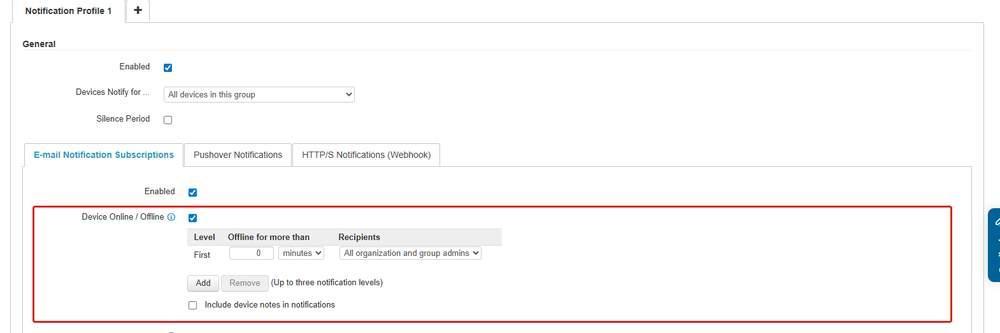
Steps 4 to 6. On E-mail Notification Subscriptions, Enabled and Device Online / Offline are selected. The block outlined in red contains the Level, Offline for more than and Recipients table, Add and Remove for up to three notification levels, and Include device notes in notifications.
How soon a device counts as offline is set by Minimum Communication Interval (13.6.3 Minimum Communication Interval). If the e-mail does not arrive, check that Receive E-mails in your own profile includes Notifications. See 2.10.3 Your Account.
13.7.7. Mobile App Notifications
Not a configurable block. The page states that you receive notifications if you have installed the InControl app and signed in with the same account, and that notification choices are made inside the app. A Download InControl app link is provided.

The Mobile App Notifications block. It contains a line of text and the Download InControl app link, and no settings.
13.7.8. ContentHub Storage Threshold

Device managed is selected. The other option takes a percentage, shown at 90% (Default).
Option | Effect |
Device managed | The device decides |
Notify when storage usage reaches ... of capacity | InControl 2 notifies at the selected percentage |
The percentage list is 99%, 98%, 97%, 96%, 95%, 90% (Default), 85%, 80%, 75%, 70%.
13.8. Report E-mailing (Group Level)
Schedules the group's reports to be e-mailed on a fixed cycle. This screen schedules delivery only. It does not change how long the underlying data is kept, and retention differs per report family. See the Reports chapter (11 Reports) for the date range each report offers. The organization level screen (9.5 Report E-mailing (Organization Level)) offers Usage Reports only. Device Reports, Wi-Fi Reports, Captive Portal Reports and Connection Test Reports are e-mailed from this group-level screen.
Where to find it
Group > Settings > Report E-mailing
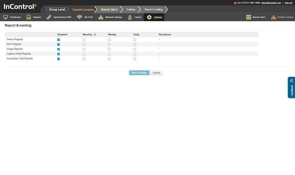
One row per report family and one checkbox per frequency. Disabled is a separate column.
13.8.1. What This Screen Shows
A grid of report families against frequencies.

The default grid: Disabled selected for all five report families, and a dash in every Recipients cell.
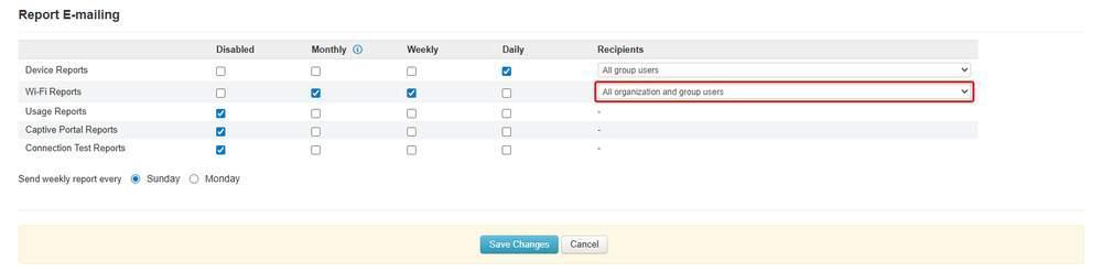
Monthly and Weekly selected for Wi-Fi Reports. Its Recipients dropdown, outlined in red, replaces the dash. Device Reports keeps its Daily schedule and its own dropdown, and Send weekly report every appears below the grid with Sunday or Monday.
Column | What it shows |
Disabled | Turns e-mailing off for that report family |
Monthly | E-mails the report on the first of every month, per the tooltip on the column |
Weekly | E-mails the report weekly. Selecting it reveals Send weekly report every, with a choice of Sunday or Monday |
Daily | E-mails the report daily |
Recipients | Who receives that report family |
The five report families are:
- Device Reports
- Wi-Fi Reports
- Usage Reports
- Captive Portal Reports
- Connection Test Reports
Each frequency is an independent checkbox, so one report family can be sent on more than one cycle.
13.8.2. Recipients Appear Only Once a Frequency Is Chosen
The Recipients cell shows - for every report family until a frequency is selected for that family. Selecting one changes that family's cell to a dropdown. Families with no frequency selected keep their -.
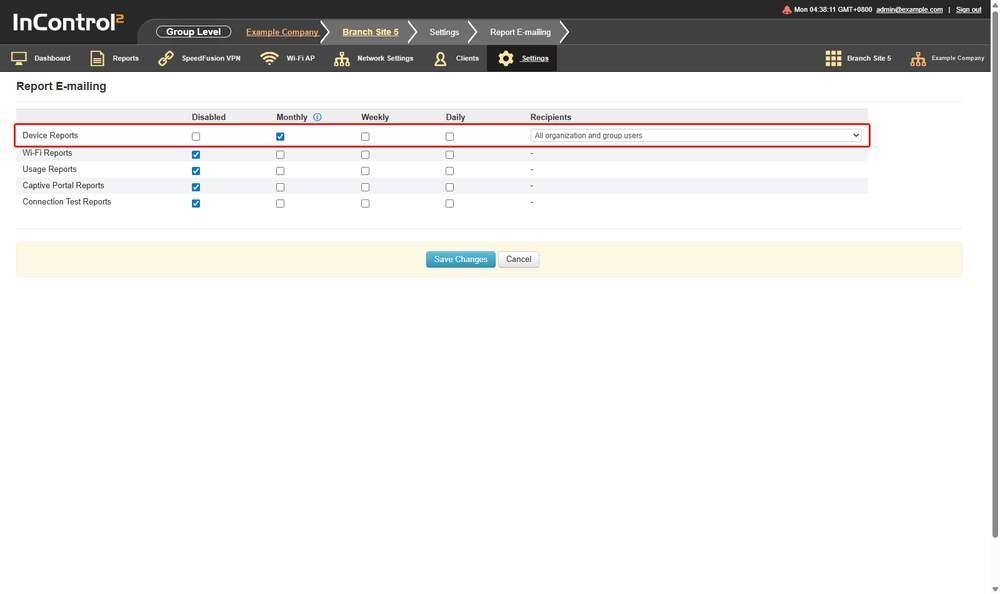
Monthly selected for Device Reports. Only that row, outlined in red, has a Recipients dropdown, and the four families below it still show a dash.
For Device Reports, Wi-Fi Reports, Usage Reports and Connection Test Reports, the dropdown offers nine choices, in this order:
- All organization and group users
- All organization and group administrators
- All organization users
- All organization administrators
- All organization viewers
- All group users
- All group administrators
- All group viewers
- Other e-mail addresses
Captive Portal Reports has its own shorter list, with no split between organization and group scope:
- All super organization admins, captive portal admins and viewers
- All captive portal admins and viewers
- Other e-mail addresses
Note the following:
- Recipients are chosen per report family. Each family has its own dropdown.
- The nine option list distinguishes users, administrators and viewers, and organization scope from group scope.
- Other e-mail addresses is the only option on either list that does not select by role. The others resolve to accounts in the organization or in the group.
13.8.3. Controls on This Screen
Control | What it does |
Save Changes | Saves the schedule. Disabled until something is changed |
Cancel | Discards the changes |
13.9. Firmware Policy (Group Level)
Sets the firmware version each product model in the group should run, and when the update should happen.
Where to find it
Group > Settings > Firmware Policy
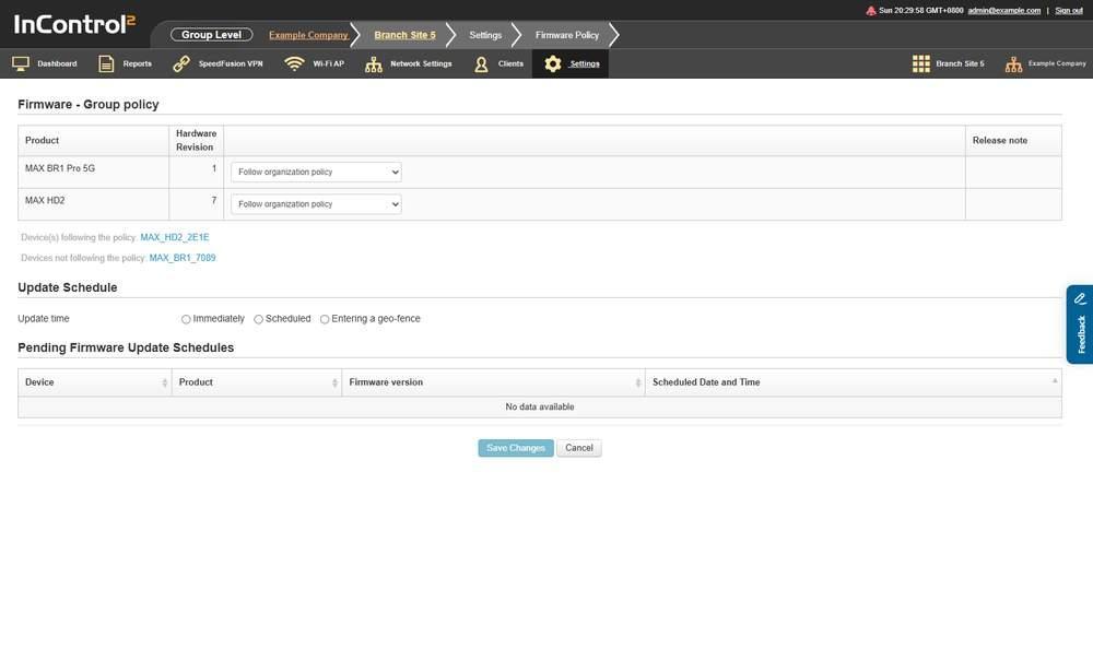
One policy row per product and hardware revision. Below the grid, InControl 2 lists which devices follow the policy and which do not.
13.9.1. The Policy Grid
Firmware - Group policy has one row per product model and hardware revision combination.

Two policy rows, one per product and hardware revision, each set to Follow organization policy.
Column | What it shows |
Product | The product model, for example MAX BR1 Pro 5G |
Hardware Revision | The hardware revision the row applies to |
Firmware version | The version this group should run, selected from a dropdown. The default is Follow organization policy, so a group follows the organization policy until a version is set |
Release note | Link to the release note for the selected version |
Each row's dropdown begins with two policy choices before the version list:
- Follow organization policy
- Firmware management disabled
and ends with Custom, after the version list. Custom presents its own fields when selected.
The version list differs per row, because each product and hardware revision has its own list of released versions.
The policy grid also has Upgrade only, which determines which devices a selected version reaches. It has the same name and tooltip on the organization and device-level firmware screens.
Upgrade only | Which devices receive the firmware |
Selected | Only devices running a firmware version lower than the specified one |
Not selected | All devices running a different version of firmware, not only those on an older one |
Leave it selected for an upgrade only policy. When it is cleared, the policy enforces the specified version on every device that differs from it, so a device running a newer build is returned to the selected build.
Below the grid InControl 2 lists which devices follow the policy and which do not, as Device(s) following the policy: and Devices not following the policy:. Each device name links to that device's firmware page.
13.9.2. Update Schedule
Update Schedule is a section at the bottom of the page, below the policy grid. Its Update time choice applies to the whole policy, not to one row.
Option | Effect |
Immediately | The update runs as soon as the policy is saved |
Scheduled | The update runs at a set time |
Entering a geo-fence | The update runs when the device enters a geo-fence. The screen states: You should create a geofence here for the affected devices and choose the action "Apply Firmware". |
Selecting Scheduled reveals these fields:
Field | What it sets |
Start date | The day updates begin |
Start time | The time updates begin |
Daily end time | Optional. The screen states: If this is defined, updates will only be performed between the start and end time on the start day and subsequent days. |
Time interval between devices | A gap of 0 to 59 minutes and 0 to 59 seconds between one device's update and the next |
Caution: Saving the policy with Update time at Immediately sends the firmware to every matching device of that product in the group at once. With Upgrade only cleared, this includes returning newer devices to the selected version. On a large group, select Scheduled and confirm Upgrade only before clicking Save Changes.
Entering a geo-fence relates to Geo-fencing below (13.11 Geo-fencing), where a fence has an Apply Firmware action.
13.9.3. Pending Firmware Update Schedules
Column | What it shows |
Device | The device the update is queued for |
Product | The product model |
Firmware version | The version queued |
Scheduled Date and Time | When the update will run |
An empty list shows No data available.

The pending list with nothing queued, showing its four columns.
13.9.4. Rolling Out Firmware in Stages
Firmware Policy selects devices by product model and hardware revision only. It has no selection by tag, so stage a rollout with groups or with per device settings.
- 1.Select a pilot. Either use a small pilot group with its own Firmware Policy, or set one or two pilot devices to the new version on Device > Settings > Firmware Management (see Firmware Management in Device Level Tools, 16.1 Firmware Management).
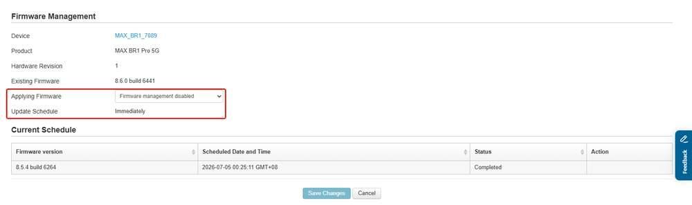
Step 1. Applying Firmware and Update Schedule, outlined in red, on a pilot device's Firmware Management screen. Current Schedule below lists the updates queued for the device.
- 2.On each pilot, keep Upgrade only selected and set Update Schedule to Scheduled, so the update runs at a set time rather than on save.
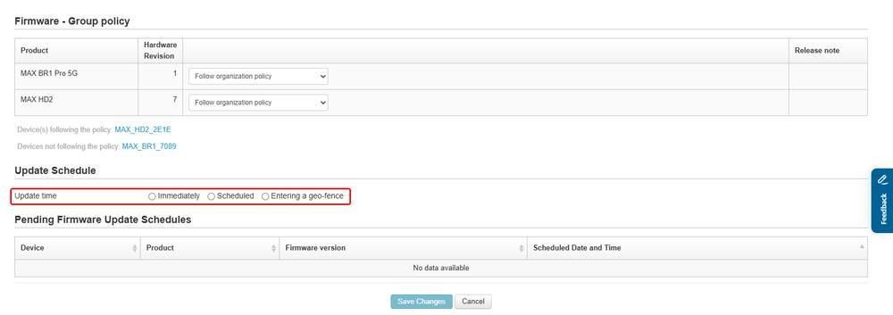
Steps 2 and 4. Update time, outlined in red, under Update Schedule. Select Scheduled. The product rows above contain the Firmware version dropdowns, and Pending Firmware Update Schedules is below.
- 3.Confirm the pilot update is queued: Current Schedule on a device's Firmware Management screen (16.1.6 Current Schedule), or Pending Firmware Update Schedules on this screen for a pilot group.
- 4.When the pilots are stable, select the same version for the product row on this screen, again with Upgrade only selected and Update Schedule at Scheduled.
- 5.Check Pending Firmware Update Schedules to confirm the devices and the time.
- 6.After the scheduled time, check Devices not following the policy: below the grid. Each device listed there has not received the version, and each name links to that device's firmware page.
- Set Daily end time to keep updates within a maintenance window. Updates run only between the start and end time, on the start day and the following days.
- Set Time interval between devices so devices update one after another rather than all at once.
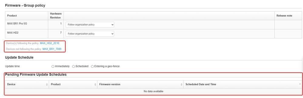
Steps 5 and 6. Pending Firmware Update Schedules lists the queued updates, and the names under Devices not following the policy, both outlined in red, are the devices still to update.
- 7.To revert a single device, open its Firmware Management screen and select Reboot to last firmware, which returns it to the firmware it ran before the current one.
13.10. Device Schedule
Defines named time schedules at group level, such as business hours, for use by other features.
Where to find it
Group > Settings > Device Schedule
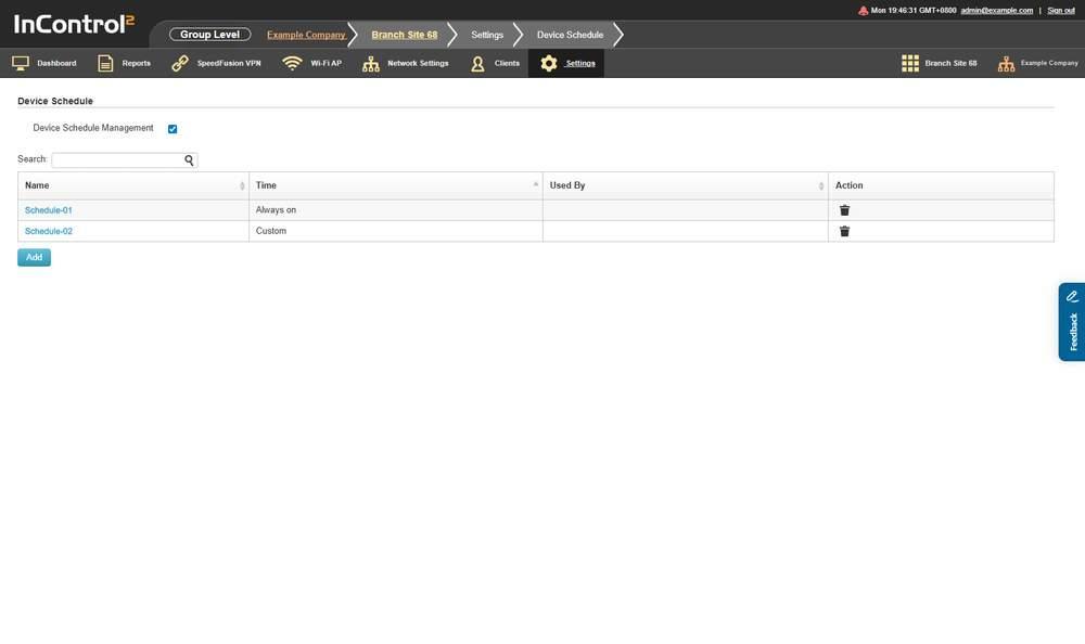
The screen with Device Schedule Management selected and schedules defined. The Time column shows the template each schedule was built from, not its hours.
13.10.1. Switching Group Management On
The screen is gated by the Device Schedule Management checkbox. Group level schedules apply only when it is selected. Before selecting the gate, read 8.1.1 Before You Tick a Manage Checkbox.
13.10.2. The Schedule List
One row per schedule defined in the group.
Column | What it shows |
Name | The schedule name |
Time | The time coverage of the schedule, shown as the Schedule Templates value it was built from, for example Always on |
Used By | What currently uses the schedule. Empty when unused |
Action | Per row actions |
An empty list shows No data available.
The Time column shows the template, not the hours. A schedule edited cell by cell in the Schedule Map shows Custom. Open the schedule to see its actual coverage.
13.10.3. Controls on This Screen
Control | What it does |
Device Schedule Management | Switches group level schedule management on or off |
Search: | Filters the schedule list |
Add | Opens the Schedule Settings editor |
13.10.4. The Schedule Settings Editor
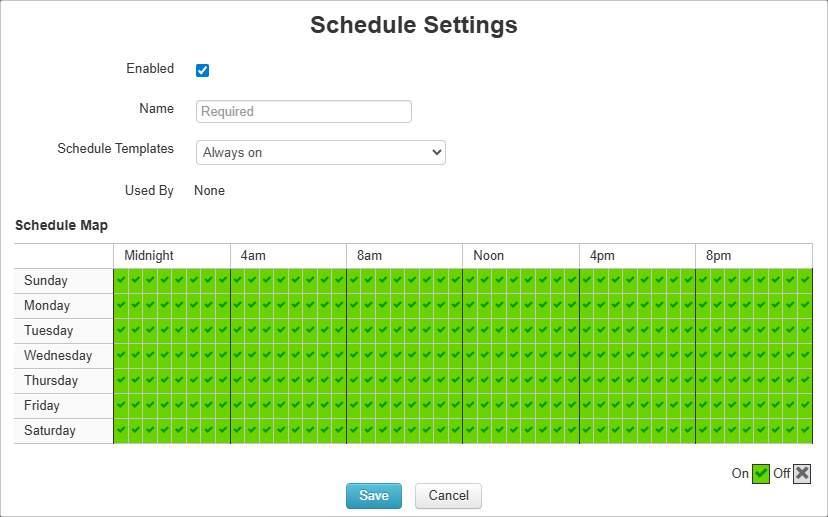
The Schedule Map at the bottom defines the schedule. Selecting a template fills it in, and individual cells can then be adjusted.
Field | Notes |
Enabled | Turns the schedule on or off without deleting it |
Name | The schedule name |
Schedule Templates | Always on, Always off, 8am to 5pm on weekdays only, Weekdays only, Custom |
Used By | Shows what uses this schedule. A new schedule shows None |
Schedule Map | A grid of the seven days against the hours of the day, marked On or Off |
The Schedule Map is labelled along the top with Midnight, 4am, 8am, Noon, 4pm and 8pm, and down the side with Sunday through Saturday.
The editor has Save and Cancel buttons.
13.11. Geo-fencing
Defines geographic fences and the actions InControl 2 takes when a device enters or leaves one, for example applying firmware only when a vehicle enters a depot.
Where to find it
Group > Settings > Geo-fencing
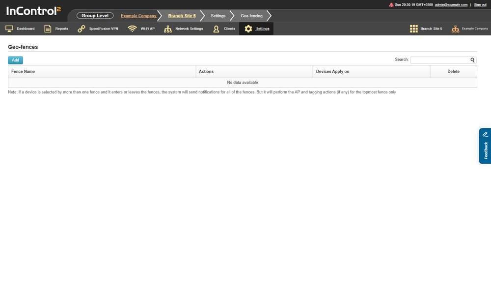
The fence list. The note below describes what happens when several fences select the same device.
13.11.1. The Fence List
Column | What it shows |
Fence Name | The fence name |
Actions | The actions configured on that fence |
Devices Apply on | Which devices the fence applies to |
Delete | Removes the fence |
An empty list shows No data available.
The fence list page states: Note: if a device is selected by more than one fence and it enters or leaves the fences, the system will send notifications for all of the fences. But it will perform the AP and tagging actions (if any) for the topmost fence only. Fence order affects the AP and tagging actions, but not notifications.
13.11.2. Controls on This Screen
Control | What it does |
Search: | Filters the fence list |
Add | Opens the fence editor |
13.11.3. The Fence Editor
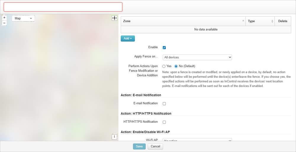
The map on the left defines the zone. The settings and action blocks on the right define what happens on entry and exit.
Top of the editor:
Field | Notes |
Map | The map on which the zone is drawn. Its controls are Zoom in, Zoom out and Attributions. Below it is a zone list with the columns Zone, Type and Delete and its own Add button. The zone list shows No data available until a zone is drawn, and the Type value of a zone appears in its row after the zone is added |
Enable | Turns the fence on or off without deleting it |
Apply Fence on... | All devices, Devices with any of the following tags:, Devices with none of the following tags:. The default is All devices, so a new fence applies to every device in the group until this is changed |
Perform Actions Upon Fence Modification or Device Addition | Yes or No (Default) |
The editor describes Perform Actions Upon Fence Modification or Device Addition: by default no action is performed when a fence is created, modified or newly applied to a device, until the device enters or leaves the fence. Selecting Yes performs the actions as soon as InControl 2 receives the devices' next location points, and e-mail notifications are sent for each of those devices if enabled.
Caution: Yes on Perform Actions Upon Fence Modification or Device Addition performs the fence's actions on every device the fence applies to as soon as InControl 2 receives its next location point, rather than on the next entry. Check Apply Fence on... before saving.
Action blocks:
Action | Options |
E-mail Notification | A checkbox. Selecting it reveals Recipient E-mail Addresses, Subject, Message Content, Show Translation Settings and Silence Period |
HTTP/HTTPS Notification | A checkbox. Selecting it reveals a URL field |
Enable/Disable Wi-Fi AP | No action, Enable on leave, disable on enter, Disable on leave, enable on enter. The default is No action, so a new fence does not change Wi-Fi AP state until this is set |
Device Tagging | Device Tagging. Adds tags to devices as they enter or leave the fence |
Firmware Application | Apply Firmware |
Stow/Unstow Starlinks | No action, Stow on enter, unstow on leave, Stow on leave, unstow on enter. The default is No action, so a new fence does not stow any Starlink until this is set |
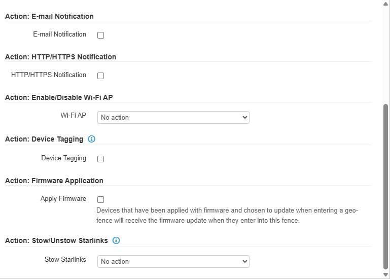
The six action blocks, on the right side of the editor below the settings. Wi-Fi AP and Stow Starlinks are dropdowns; the other four are checkboxes.
For the firmware action the editor states that devices applied with firmware and set to update when entering a geo-fence receive the firmware update when they enter this fence. This corresponds to Entering a geo-fence on the Firmware Policy screen (13.9.2 Update Schedule).
To update a mobile fleet at a depot:
- 1.Draw a fence around the depot in the fence editor.
- 2.Select Apply Firmware on that fence and save it.
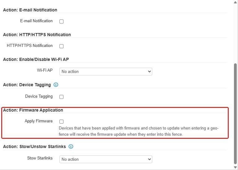
Step 2. The Apply Firmware checkbox, outlined in red, under Action: Firmware Application in the fence editor.
- 3.On Firmware Policy, under Update Schedule, set Update time to Entering a geo-fence. See 13.9.2 Update Schedule.
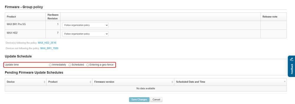
Step 3. Update time, outlined in red, under Update Schedule on Firmware Policy. Entering a geo-fence is the third choice.
- 4.Vehicles receive the firmware when they enter the depot fence.
The editor has Save and Cancel buttons.
13.11.4. The E-mail Notification Subject Line
The E-mail Notification action block has a Subject field, which can contain variables. The tooltip lists every available variable:
Variable group | Variables |
Device | ${device_name}, ${device_names}, ${device_url}, ${sn} |
Fence and event | ${fence_name}, ${entered_or_left}, ${event_type}, ${result} |
Location and speed | ${latitude}, ${longitude}, ${location}, ${current_speed}, ${speed_limit} |
Time | ${date_time}, ${current_year}, ${unixtime}, ${gps_unixtime} |
Organization | ${organization_id} |
The editor's note states that ${device_name} is substituted by the GPS device and all devices following its GPS location. The default message reads The device(s) ${device_name}.
13.11.5. Device Tagging Turns a Fence into a Configuration Trigger
The Device Tagging tooltip states that tags are added to devices when they enter or leave a geo-fence, and that any tag-based configuration becomes geo enabled as a result.
Tags drive device selection on most other screens in this chapter. Firewall rule sets, GPIO profiles, Serial-port-based InTouch profiles, InControl Options and External InControl Appliance Settings all offer Devices with any of the following tags and its variants. When one of those selects a tag applied by a fence, the configuration follows the device's location.
The tooltip gives an example: to enable SSID A while a device is in zone A, and to enable SSID B and disable SSID A when the device moves to zone B, tag the device from each fence and select on that tag in the Wi-Fi configuration.
Where several fences select the same device, tagging actions run for the topmost fence only (13.11.1 The Fence List), so fence order determines which location based configuration applies.
13.11.6. Stowing Starlinks by Location
The Stow/Unstow Starlinks action stows or unstows the Starlinks connected to this group's devices' WANs, matched by the WAN names given, on entering or leaving the fence.
The tooltip adds:
- The action requires firmware 8.5.0 or above. Devices on older firmware do not act on it.
- Targeting is by WAN name, not by device. Use consistent WAN names across the fleet so the action reaches every intended device.
13.12. Bulk Configurator
Applies device configuration files to many devices at once, and states which settings such a file can and cannot change.
Where to find it
Group > Settings > Bulk Configurator
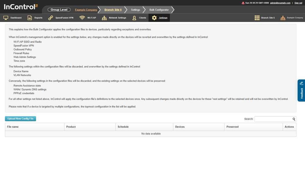
The rules at the top of the page govern how a configuration file is applied. Read them before uploading a file.
13.12.1. What the Page Tells You First
The page opens with the rules that govern how a configuration file is applied. They explain why a setting in a file may not reach the device.
Category | Settings | Outcome |
Managed by InControl | Wi-Fi AP SSID and Radio, SpeedFusion VPN, Outbound Policy, Firewall Rules, Web Admin Settings, Time zone | Where InControl 2's management option is enabled, changes made directly on the devices are reverted and overwritten by the settings defined in InControl 2 |
Discarded from the file | Device Name, VLAN Networks | Discarded, and overwritten by the settings defined in InControl 2 |
Preserved on the device | Remote Assistance state, WANs' Dynamic DNS settings, PPPoE credentials | Discarded from the file, and the existing device settings are preserved |
Everything else | All other settings | Applied from the file once. Later changes made directly on the device are retained and are not overwritten by InControl 2 |
Managed settings are enforced continuously. Other settings in a bulk configuration file are applied once.
The page also states that if a device is targeted by multiple configurations, the topmost configuration in the list is applied.
13.12.2. The Configuration List
Column | What it shows |
File name | The uploaded configuration file |
Product | The product the file applies to |
Schedule | When the file is applied |
Devices | Which devices the file targets |
Preserved | Which settings are preserved |
Actions | Per row actions |
An empty list shows No data available.
13.12.3. Controls on This Screen
Control | What it does |
Search: | Filters the configuration list |
Upload New Config File | Opens the Configuration File Upload dialog, described below |
13.12.4. The Configuration File Upload Dialog
Upload New Config File opens a dialog headed Configuration File Upload.

The dialog contains the file control, with Save and Cancel below it.
Control | What it does |
Upload | Supplies the configuration file |
Save | Adds the file to the configuration list |
Cancel | Cancels the upload |
13.13. GPIO
Defines GPIO port profiles at group level and applies them to selected devices, for example for ignition sensing across a vehicle fleet. GPIO is a hardware feature. Only devices with GPIO ports can use a profile.
Where to find it
Group > Settings > GPIO
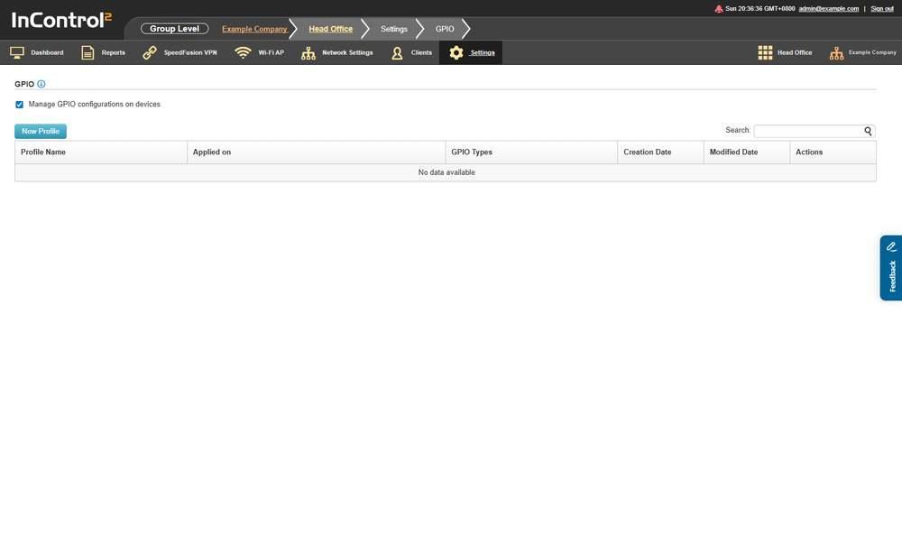
The screen is gated. Manage GPIO configurations on devices must be selected before group level profiles take effect.
13.13.1. Switching Group Management On
The screen is gated by the Manage GPIO configurations on devices checkbox. Before selecting the gate, read 8.1.1 Before You Tick a Manage Checkbox.
The tooltip on this screen states:
- GPIO profiles require firmware 8.6.0 or above. Devices on older firmware do not receive them.
- If a device is selected by more than one profile, the profile created earlier is applied. Creation order determines the profile, not list position.
13.13.2. The Profile List
Column | What it shows |
Profile Name | The profile name |
Applied on | Which devices the profile targets |
GPIO Types | The GPIO types the profile configures |
Creation Date | When the profile was created |
Modified Date | When it was last changed |
Actions | Per row actions |
An empty list shows No data available.
13.13.3. Controls on This Screen
Control | What it does |
Manage GPIO configurations on devices | Switches group level GPIO management on or off |
Search: | Filters the profile list |
New Profile | Opens the GPIO profile editor |
13.13.4. The GPIO Profile Editor
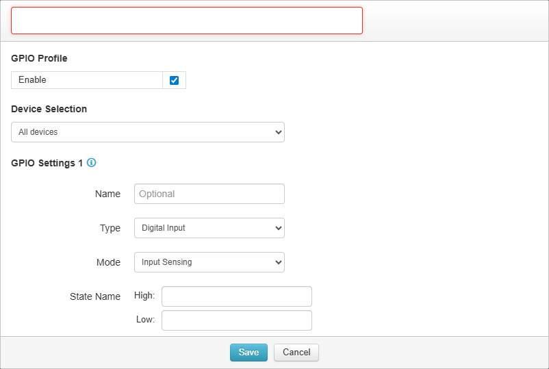
One port block per GPIO port. Add GPIO Port appends another block to the profile.
Field | Notes |
Enable | Turns the profile on or off without deleting it |
Device Selection | All devices, Devices with any of the following tags, Devices with all of the following tags, Devices with none of the following tags |
Name | The profile name |
Each port block under GPIO Settings is numbered, with an information icon and a delete icon in its heading. A block with Type set to Digital Input contains:
Field | Options and notes |
Name | The port name. Marked Optional |
Type | Digital Input, Digital Output, Analog Input |
Mode | Input Sensing, Input Transition Sensing, Ignition Sensing, Input Reset Pin |
State Name High: | Label shown for the high state. Use a name that describes the state of the connected equipment |
State Name Low: | Label shown for the low state |
Delay | A number, in seconds |
The editor has Save and Cancel buttons.
13.13.5. Adding a Second Port
Add GPIO Port appends another numbered block, GPIO Settings 2, below the first. Each block has its own Add GPIO Port button.
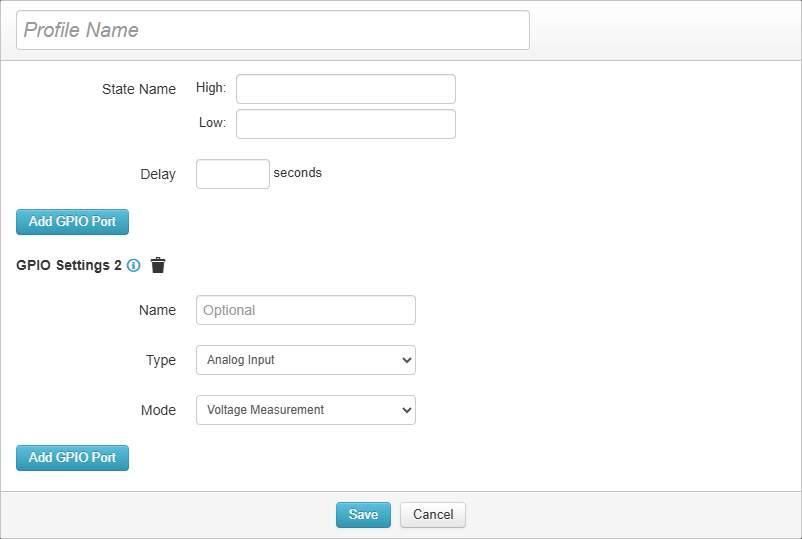
GPIO Settings 2 with Type set to Analog Input. Unlike the first block, it has no State Name or Delay fields, and Mode offers a single option.
The fields in a block depend on the selected Type. With Type set to Analog Input:
Field | Options and notes |
Name | The port name. Marked Optional |
Type | Digital Input, Digital Output, Analog Input |
Mode | Voltage Measurement is the only option |
An Analog Input block has no State Name fields and no Delay field. Those three fields belong to Digital Input. Digital Output is the third Type and presents its own fields when selected.
13.13.6. How Blocks Are Matched to Physical Ports
Blocks are not assigned to a physical port manually. A tooltip in the editor describes how InControl 2 matches them:
- Blocks are applied sequentially, in the order they appear in the profile.
- Each block is assigned to the first available GPIO port that is currently unconfigured and supports that block's Type and Mode.
- That port then counts as configured.
- The process continues until every block has been applied, or until every GPIO port on the device has been configured.
Block order therefore determines port assignment, and reordering blocks moves them to different physical ports. A block whose Type and Mode no port supports is not applied. This applies on a mixed fleet where models have different ports.
13.14. Serial-port-based InTouch
Defines serial port profiles at group level so that serial attached equipment at many sites can be reached through InTouch.
Where to find it
Group > Settings > Serial-port-based InTouch
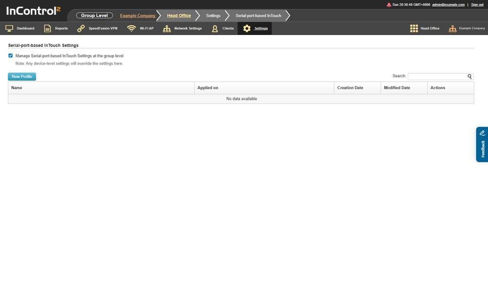
The screen is gated, and the note below the checkbox states that device level settings override the settings made here.
13.14.1. Switching Group Management On
The screen is gated by the Manage Serial-port-based InTouch Settings at the group level checkbox. Before selecting the gate, read 8.1.1 Before You Tick a Manage Checkbox.
Directly below it the page states: Note: Any device-level settings will override the settings here. Group-level settings apply only where no device level setting exists. If a profile does not apply, check the device settings.

The gate checkbox selected, with the note that device level settings override the settings made here.
13.14.2. The Profile List
Column | What it shows |
Name | The profile name |
Applied on | Which devices the profile targets |
Creation Date | When the profile was created |
Modified Date | When it was last changed |
Actions | Per row actions |
An empty list shows No data available.
The editor states: Note: If two enabled profiles are applied to the same switch, the first profile from the top will be applied. Profile order determines which profile applies.
13.14.3. Controls on This Screen
Control | What it does |
Manage Serial-port-based InTouch Settings at the group level | Switches group level management on or off |
Search: | Filters the profile list |
New Profile | Opens the profile editor |
13.14.4. The Profile Editor
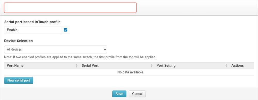
The port list is empty until New serial port is used. Device Selection at the top determines which devices the profile reaches. The empty name box at the top is outlined in red until a profile name is entered.
Field | Notes |
Enable | Turns the profile on or off without deleting it |
Device Selection | All devices, Devices with any of the following tags, Devices with all of the following tags, Devices with none of the following tags |
Name | The profile name |
The port list has the columns Port Name, Serial Port, Port Setting and Actions, and shows No data available while empty.
The editor has Save and Cancel buttons.
13.14.5. Adding a Serial Port
New serial port opens a second editor over the profile, where a single port is defined. Use it once for each port on the device. The profile's port list shows the defined ports.
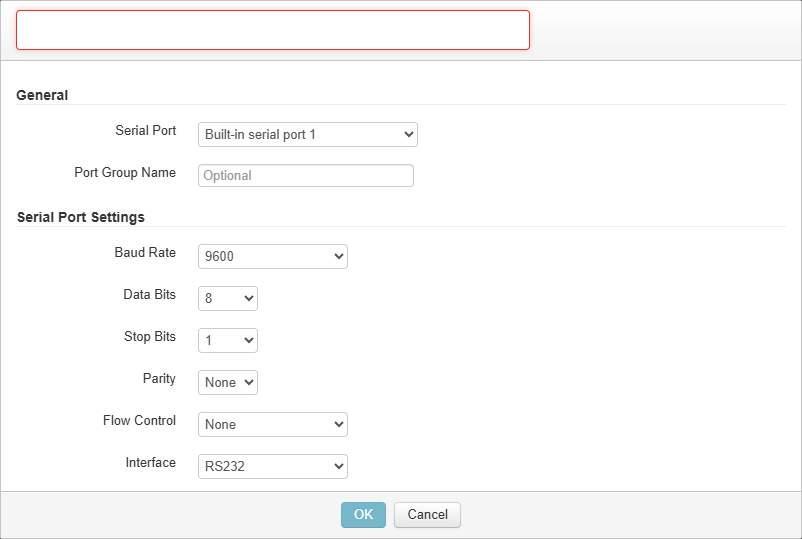
The port editor over the profile. The name box at the top is outlined in red until it is filled, and the port parameters are grouped under General and Serial Port Settings.
A port name is required.
General
Field | Options |
Serial Port | Built-in serial port 1, A USB serial port |
Port Group Name | Free text. Marked Optional |
Serial Port Settings
Field | Options | Opens on |
Baud Rate | 600, 1200, 2400, 4800, 9600, 19200, 38400, 57600, 115200, 230400 | 9600 |
Data Bits | 8 is the only option | 8 |
Stop Bits | 1 is the only option | 1 |
Parity | None, Even, Odd | None |
Flow Control | None, RTS/CTS, Xon/Xoff | None |
Interface | RS232 is the only option | RS232 |
Two more fields are below these:
Field | Notes |
Inactivity Timeout | A number, in second(s) |
Health Check Keystrokes | Free text. The editor states the escapes it accepts: \s for space, \n for carriage return, \t for tab |
Note the following:
- The editor defaults are 9600, 8, 1, None, None. Match these to the connected equipment.
- The port editor closes with OK and Cancel. The profile is saved separately, with the Save button on the profile editor.
13.15. Docker Management
Holds container scripts for the group and shows which script is applied to each device. A script created here is available to the devices in this group.
Where to find it
Group > Settings > Docker Management
Docker Management. The Scripts panel is above and the Devices panel below, each with its own search box.
13.15.1. What This Screen Shows
Two panels, in this order.
Panel | What it covers |
Scripts | The container scripts held for this group |
Devices | The devices in the group, and the script applied to each |
13.15.2. Scripts
Column | What it shows |
Script Name | The script |
Actions | Per script actions |
Create Script adds a script. The grid shows No data available until a script is added.
The Create Script dialog. A name field at the top, Script content for the docker run commands with notes below, and Container Settings with Container No., Login ID, Password and Auto Update?.
13.15.3. Devices

The Devices panel with one device and no script applied. Apply a script is below the grid and is greyed.
Column | What it shows |
Device Name | The device |
Applied Script | The script applied to it, or a dash. A dash means no script is attached, which is the default state |
Status | The state of that script on the device |
Actions | Per-device actions |
Apply a script below the grid attaches a script to a device.
13.16. Ad Delivery Service
Where to find it
Group > Settings > Ad Delivery Service
This entry opens the Ad Delivery Service, a separate site at ad.peplink.com, outside the InControl 2 interface. The Ad Delivery Service is documented by that service and is outside the scope of this manual.
Two related roles, Ad Delivery Service Administrator and Ad Delivery Service Viewer, are assigned on the Group Settings screen below (13.17.2 Administration).
13.17. Group Settings
Names the group, sets its time zone and address, controls what group level administrators and viewers can see and do, and holds the group's Starlink API credentials.
Where to find it
Group > Settings > Group Settings
The Administration block at the top separates organization users, listed for reference, from group users, whose roles can be changed here.
13.17.1. Group Name and Description

Group Name and Description at the top of the page.
Field | Notes |
Group Name | The name of the group |
Description | Free text description of the group |
13.17.2. Administration
The block contains two lists. Organization Users is read only. Add Group Users in the blank row and assign the narrowest suitable role. No group role extends beyond this group.

The Group Users list. Each row has a Role dropdown, a Remarks field and two action icons, and the empty row at the bottom ends in a + icon.
Organization Users is a read-only list. The page states that these users have administrator access to all groups in the organization, including this one.
Column | What it shows |
First Name | Given name |
Last Name | Family name |
The account e-mail address | |
Account Status | For example Active |
Role | For example Organization Administrator or Super Organization Administrator |
Remarks | Free text note |
Group Users lists the users with administrator access to this group only. It adds an Actions column, and its Role and Remarks values are editable.
The Role dropdown offers:
- Group Administrator
- Group Viewer
- Captive Portal Administrator
- Captive Portal Report Viewer
- Ad Delivery Service Administrator
- Ad Delivery Service Viewer
- Group Dashboard Viewer
- InTouch User
- Fleet Manager
A tooltip on the Group Users list describes each role:
Role | What the role may do |
Group Administrator | Full access to the group. Can view this group's dashboard, reports, settings and device details, and can make configuration changes. Cannot access other groups in the organization, and cannot access social user data |
Group Viewer | Can view the dashboard, reports, device details and some settings for this group. Has no editing ability, and cannot access other groups in the organization |
Group Dashboard Viewer | Can see this group's dashboard only. Cannot see reports, settings or device details. Has no editing capability, and cannot access other groups in the organization |
Captive Portal Administrator | Access to the Captive Portal section in this group only. Also has read and deletion rights on social user data |
Captive Portal Report Viewer | Access to the Captive Portal Reports in this group only. Also has read access rights on social user data |
InTouch User | InTouch access to client devices over TCP/IP, or to devices' serial ports |
Fleet Manager | Access to the map on this group's dashboard page only |
Note the following when assigning roles:
- Social user data access belongs to the Captive Portal roles, not the group roles. A Group Administrator has full access to the group but cannot access social user data. A Captive Portal Administrator can read and delete it, and a Captive Portal Report Viewer can read it.
- Group Viewer and Group Dashboard Viewer differ. A Group Viewer sees reports, device details and some settings. A Group Dashboard Viewer sees the dashboard only.
- InTouch User is an access role, not a viewing role. It grants access to client devices over TCP/IP and to devices' serial ports.
A blank row at the bottom of the Group Users list adds an administrator, with First Name, Last Name, E-mail, a Role dropdown and Remarks. The list is exported and imported through Download as CSV and Upload CSV.
Adding a group user
- 1.Open Group > Settings > Group Settings and go to Administration, Group Users.
- 2.In the blank row at the bottom of the list, enter First Name, Last Name and E-mail.
- 3.Select a Role, for example Group Viewer for read-only access, and add Remarks if required.
- 4.Click the + icon at the end of the row.
- 5.Click Save Changes at the bottom of the page. The page confirms User(s) ... added successfully.
When the e-mail address already has a Peplink ID, the user is listed as Active immediately, under the name on that Peplink ID rather than the name entered. The user receives an e-mail from InControl 2, subject Added to InControl group: <group name>, with a link to the group. No acceptance is required: the user can open the group at their next sign in.
To remove access, click Remove on the user's row, then Save Changes. The page confirms User(s) ... removed successfully. The user receives an e-mail, subject Removed from InControl group: <group name>, which names the group, the organization and the administrator who removed them.
Two tooltips on the list read Suspended this user account's Group Administrator privileges. and Reactivated this user account's Group Administrator privileges. Suspending and reactivating act on the user's privileges, and a suspended administrator is reactivated from the same list. Each row also has a Remove control.
13.17.3. Time Zone

The Time Zone dropdown with Devices follow this time zone setting below it.
Field | Notes |
Time Zone | A list of UTC offset entries, from (UTC-12:00) International Date Line West to (UTC+14) Kiritimati Island |
Devices follow this time zone setting | Checkbox. Applies the group time zone to the devices themselves |
The time zone alone changes how InControl 2 displays times. The checkbox applies the time zone to the devices.
13.17.4. Advanced Settings
Three settings have three options, where the third follows the organization and shows the organization's current value in brackets.
The Advanced Settings block. The three option settings are at the top, followed by the checkbox groups and the standalone checkboxes.
Setting | Options |
Show Subscription Expiration Dates and Notices to non-Organization Administrators | Yes, No, Follow Organization's (Yes) |
Send Warranty and Subscription Renewal Reminder to non-Organization Administrators | Yes, No, Follow Organization's (Yes) |
Display Internet & Device Availability on Group Dashboard | Yes, No, Follow Organization's (No) |
The other settings are checkboxes, grouped by the users they affect.
Group | Checkboxes |
Allow Group Administrators to | remove or move devices; change SIM Pool bandwidth quota; change the stop routing settings in SIM pools |
Display to Group Administrators | Group Settings; Firewall Rules; Outbound Policy; Device System Management; Operation Log |
Display to Group Viewers | Operation Log; Maps |
Standalone | Display All Settings to Viewers; Hide Default Password Warnings; Hide Firmware Availability Indicators; Hide Feedback Button; Collect WAN Usage data from AP Ones in Bridge Mode |
These checkboxes control what a Group Administrator or Group Viewer can see. If a menu is missing for a group user, check this block first.
Four tooltips in this block state the limits of these checkboxes:
- Display to Group Administrators only suppresses the display of those pages to Group Administrators on the browser end.
- change SIM Pool bandwidth quota only makes the SIM pools' bandwidth quota field uneditable on the browser end for Group Administrators.
- change the stop routing settings in SIM pools only makes the SIM pools' Stop Routing User Traffic option uneditable on the browser end for Group Administrators.
- Display All Settings to Viewers refers to group viewers only.
The first three act on the browser end only and are not access control. To restrict a user's abilities, assign a narrower role in Administration above.
Hide Default Password Warnings and Hide Firmware Availability Indicators hide the Device's web admin password remains with the default one. and Firmware upgrade is available. status icons on Device Management (13.1.2 Status Icons). Leave them cleared on any group monitored for those conditions.
The tooltip on Collect WAN Usage data from AP Ones in Bridge Mode states that since InControl 2.14.1, no WAN usage data is collected from AP Ones in bridge mode, because they have no WAN interface. Enabling the option collects that usage as WAN usage.
13.17.5. Peplink App Settings
The section heading on screen is Peplink App.

The Peplink App block. Each setting offers Yes, No, or the organization's value in brackets.
Setting | Options |
Allow managing devices in Peplink App | Yes, No, Follow Organization's (No) |
When removing a device from the app, remove it from InControl too | Yes, No, Follow Organization's (No) |
With the second setting at Yes, removing a device in the app also removes it from InControl 2.
13.17.6. Starlink API Settings

The Starlink API Settings block. The Client Secret is masked, with Show and Verify beside it.
Field | Notes |
Starlink Client ID | The client identifier |
Starlink Client Secret | The client secret, masked. A Show button reveals it |
Verify | Checks the credentials |
13.17.7. Map
The Custom Map Markers block offers an Online marker and an Offline marker, each with a + control that uploads a replacement marker image.

Custom Map Markers, with an Online tile and an Offline tile, each with a + control.
The tooltip states the requirements: the image must be in PNG format, and the dimensions are forcefully resized to 50 by 50. Use a square PNG to avoid distortion.
13.17.8. Address
The Address block: Country, Address, the map preview with its zoom, Map, full screen and attribution controls, and the two Location fields.
Field | Notes |
Country | A full country list, from Afghanistan to Zimbabwe |
Address | Free text street address |
Location | Latitude and longitude, entered as text, with a map preview |
The map preview has + and – zoom buttons, an i button whose tooltip reads Attributions, and a Toggle full-screen button.
The tooltip on the block states: The Location field may not correspond to the address. The two are entered separately, so check the coordinates separately from the street address.
13.17.9. Controls on This Screen
Control | What it does |
Save Changes | Saves the changes. Disabled until something is changed |
Cancel | Discards the changes |
13.18. Operation Log (Group Level)
Records the changes administrators made in the group, with the old and new values.
It records changes made in InControl 2. Changes made on the device itself through Remote Web Admin or Web CLI, and Device Tools actions such as Ping, do not appear here. For those, the device's own Event Log (15.9 Event Log (Device Level)) shows each Remote Web Admin session, with the user and source address, and a Changes applied entry when a change is applied on the device.
Where to find it
Group > Settings > Operation Log

Each entry names the administrator, the device and the setting changed. The time zone of the log is stated above the table.
13.18.1. What This Screen Shows
Column | What it shows |
Time | When the change was made |
Admin | The administrator who made it |
Device | The device affected. The device name is a link |
Page | The screen the change was made on, for example Device Management |
Label | The setting that changed, for example Reboot Starlink |
Old Value | The value before the change. - where there was none |
New Value | The value after the change. - where there is none |
Actions with no before and after value, such as a reboot, are recorded with - in both value columns.
Retention is not configurable.
Above the table the log states its time zone, for example Time Zone: (UTC+08:00) Kuala Lumpur, Singapore. Timestamps are in that time zone, not in your local time.
13.18.2. Controls on This Screen
Control | What it does |
Search: | Filters the log |
First, Previous, Page, Next, Last | Pages through the log, for example Showing 1 to 25 of 413 entries |
13.18.3. Finding What Changed Before an Outage
- 1.Note the device's Offline Time from its offline and online history (see Event Log (device level) in Device Reports, 15.9.3 Offline History and Online History).

Step 1. Each row pairs an Offline Time with the matching Online Time and the length of the gap. Note the Offline Time of the outage.
- 2.Open Group > Settings > Operation Log.
- 3.Enter the device name in Search:.
- 4.Compare each entry's Time with the Offline Time, both in the time zone stated above the table.

Steps 3 and 4. The Search: box and the Time Zone line, outlined in red, above the log. Each Time is in that time zone.
- 5.Check Page, Label, Old Value and New Value for the entries just before the outage. Changes made in the Peplink App are also recorded, under the page Peplink App Configuration.

Step 5. Page, Label, Old Value and New Value, outlined in red. A reboot shows a dash in both value columns.
- 6.For changes across several groups, use the organization level Operation Log, which adds a Group column and a Time Zone: selector (see Operation Log (organization level) in Settings (Organization Level), 9.7 Operation Log (Organization Level)).