
8. Network Settings
Network Settings holds the configuration that InControl 2 pushes to every device in a group. Most screens apply to devices only after their management checkbox is selected and saved. Each screen then handles the devices it reaches, and those it does not, in its own way. See How group management works below (8.1 How Group Management Works). One screen in this chapter is at organization level, so that a definition made once is available to every group in the organization.
8.1. How Group Management Works
This section describes which devices each screen changes, and what happens to the rest.
Most screens are gated by a Manage ... checkbox. Until it is selected and saved, InControl 2 does not change that setting on any device. After it is saved, the effect on each device depends on the screen:
Screen | Gate | Devices no profile or rule set reaches | Two profiles or rule sets reach one device |
WAN Configurations | Manage WAN configurations on Balance and MAX devices | WAN configuration kept unchanged | First profile from the top. Avoid overlap |
Outbound Policy | Manage Outbound Policy on Balance and MAX devices | Preserve (default) or clear their rules, set with Edit | First rule set from the top. Avoid overlap |
Firewall Rules | Manage Firewall Rules on Balance, MAX and FusionHub devices | Preserve (default) or clear their rules, set with Edit | Earliest creation date |
VLAN Networks | No gate. Saving sends the network to the devices Apply to selects | Confirm on one device after saving | Not applicable |
LAN Network Settings | Managed on each feature tab | A tab left unmanaged stays under local control | Avoid overlap |
Route Advertisement | Managed and Enable | Confirm on one device after saving | Not applicable. One configuration covers the whole Device Selection |
LLDP | Manage LLDP on Balance, MAX, and AP One devices | Not applicable. Each of the three selections names its own devices, and can be No devices | Not applicable |
IGMP Snooping | Manage IGMP Snooping on SD Switches | IGMP snooping disabled | First profile from the top |
Port Mirroring | Management Port Mirroring on SD Switches | Port mirroring disabled | First profile |
The following points apply to all screens in the table:
- Confirmation covers the whole group. Saving the gate on WAN Configurations, Outbound Policy or Firewall Rules opens a confirmation that covers ALL Balance and MAX devices in the group, not only the devices a profile or rule set later targets.
- Lists record dates. Rule set and profile lists show Creation Date and Modified Date.
- Shared configuration across groups. Define shared networks once in Organization-wide Grouped Networks (8.2 Organization-wide Grouped Networks). When creating a group in Organization > Organization Settings > Create Group, Settings Cloning (9.3.2 Settings Cloning) copies Firewall Rules, Outbound Policy, VLAN Networks, LAN Network Settings, Route Advertisement and Connection Tests from an existing group. Leave Include device tags selected, otherwise cloned VLAN Network profiles, Firewall Rules and Outbound Policy rule sets apply to all devices in the new group.
For the full pre-change checklist, see Making a change safely in Common Tasks (17.4 Making a Change Safely).
8.1.1. Before You Tick a Manage Checkbox
Review these points before selecting any Manage ... or Managed checkbox on a group screen. Each point is also covered elsewhere in this manual.
Saving the gate reaches the whole group. On WAN Configurations, Outbound Policy and Firewall Rules, the confirmation covers ALL Balance and MAX devices in the group, not only the devices a profile or rule set later targets.
Local changes are overwritten. Changes made on the device itself in an area InControl 2 manages are replaced by the InControl 2 settings. For Outbound Policy and Firewall Rules, the Bulk Configurator page states that they are reverted and overwritten (13.12.1 What the Page Tells You First).
A firewall rule set is the whole firewall rule list. Build each rule set to hold every rule the selected sites need. See 8.5.4 Creating a Rule Set.
Devices no profile reaches are handled per screen. WAN configuration is kept unchanged. Outbound Policy and Firewall Rules preserve the rules devices already have, which is the default. IGMP snooping and port mirroring are disabled on switches no profile selects. See the table above.
Enable Auto Roll Back first. In Group > Settings > InControl Options, select Auto Roll Back Device Configuration (13.6.1 Configuration Control). A device that cannot reach InControl 2 within 10 minutes of receiving a configuration rolls it back.
One site can keep its local settings. List it under Disable Device Configuration on in Group > Settings > InControl Options, which stops InControl 2 making any configuration change to that device.
Reverting differs per screen. Clearing Managed on Route Advertisement returns the device's settings to the values it held before InControl 2 managed them. On Outbound Policy and Firewall Rules, the Edit button beside the rule set list decides what happens upon policy removal: with preserve (the default), devices keep the rules InControl 2 last pushed, and the rules they held before are not restored; with clear, devices are left with no rules of that kind. Set this before clearing the checkbox or deleting a rule set (8.5.10 Preservation on Removal).
Before clearing WAN Configurations or Wi-Fi Management, record the current device settings. Note the WAN settings, or the SSIDs, of one or two devices through Remote Web Admin (16.5 Remote Web Admin), clear the checkbox and save, then compare. If a device is not configured as required, configure it on the device or select the checkbox again.
8.1.2. Rolling a Change Out in Waves
- 1.In Group > Settings > Device Management, select a few pilot devices and use Tag to add a pilot tag to them. See 13.1.5 The Tag Menu.
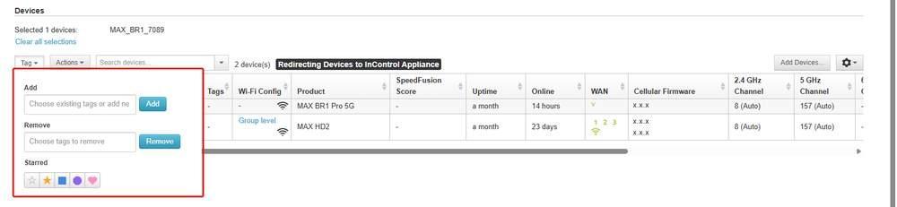
Step 1. One device selected, named on the Selected 1 devices line, and the Tag menu, outlined in red. Type the pilot tag in the Add box and click Add.
- 2.Create the rule set or profile with Device Selection set to Balance and MAX devices with any of the following tags, and enter the pilot tag.
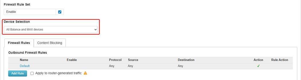
Step 2. Device Selection, outlined in red, in the firewall rule set editor. The default is All Balance and MAX devices. Change it to the tag based option before saving.
- 3.Save, then check the pilot devices as described in Check that a change arrived below.
- 4.Add the tag to the next set of devices, or change Device Selection to All Balance and MAX devices.
- 5.Widen the same rule set or profile rather than creating a second one. Where two rule sets or profiles reach one device, the first from the top applies.
Devices that must never take group changes can be left out with Balance and MAX devices with none of the following tags, or excluded from all InControl 2 configuration with Disable Device Configuration on in Group > Settings > InControl Options (13.6.1 Configuration Control).
8.1.3. Check That a Change Arrived
Applied on shows which devices a rule set or profile targets, not which devices took it. After saving:
- 1.Note the time of the save.
- 2.On the Group Dashboard device grid (10.1.3 The Devices Grid), or in Group > Settings > Device Management (13.1 Device Management (Group Level)), read Last Config Applied for the targeted devices. Hover over the value for the exact time. A time after the save means the configuration reached the device. A time before it means it has not.
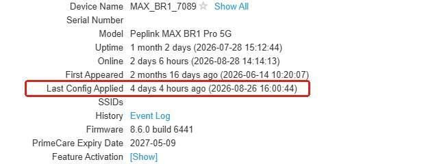
Step 2. Last Config Applied, outlined in red, on Device Details: a relative time, then the exact date and time in brackets. Compare it with the time of the save.
- 3.Check the same rows for a configuration state icon. Its tooltip names the reason a device is not taking changes:
- Config patches available
- Configuration to device stopped. Configuration rolled back.
- InControl stopped to apply configurations to device.
- Device disabled configurations from InControl
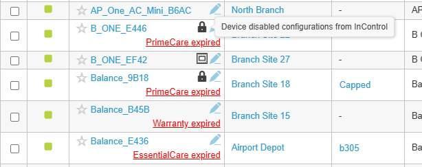
Step 3. A lock icon beside B_ONE_E446 with its tooltip open, reading Device disabled configurations from InControl. Rows without an icon carry no such condition.
- 4.Open Device Details on a sample device. The badges beside the device name confirm what InControl 2 manages there: WAN for WAN settings, OBP for Outbound Policy, and conditions such as Firewall Rules are being managed and VLAN networks are being managed. A Controller Managed badge means configuration of the device is disabled on InControl 2.

Step 4. The badges after the device name. WAN and OBP show that InControl 2 manages WAN settings and Outbound Policy on this device.
- 5.If the device rolled the configuration back, InControl 2 applies nothing further to it until a change is made to outbound policy or firewall rules. Correct the rule first, then save again. See Status badges on the heading line in Device Level Management (14.1.2 Status Badges on the Heading Line).
- 6.Check the exclusions below on a sample device before relying on the change.
The following settings do not reach every selected device:
- A rule or WAN entry scoped to a WAN name the device does not have
- Local Service Firewall Rules on firmware below 8.0.1
- Domain entries in grouped networks on firmware below 8.5.1
- Connection test profiles on a device set to status reporting only
- SSID settings on a device showing the AP Cont badge
8.2. Organization-wide Grouped Networks
Define named sets of networks and domains, such as head office ranges, once at organization level. Rules in every group can then reference them.
Where to find it
Organization > Network Settings > Organization-wide Grouped Networks
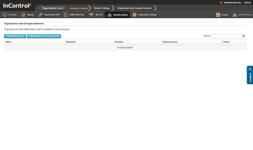
The organization level list of network groups. Note the line above the list stating that everything defined here is available in all groups.
The page states that all grouped networks defined here will be available to use in all groups.
8.2.1. What This Screen Shows
Column | What it shows |
Name | The name given to the network group |
Networks | The subnets the group contains |
Domains | The domain names the group contains |
Referenced by | Where the group is currently used |
Action | Per row actions for that network group |
An empty list shows No data available.
8.2.2. Controls on This Screen
Control | What it does |
Add Network Group | Opens the network group editor |
Import Network Groups from File | Builds network groups from a file rather than by hand |
Search | Filters the list |
8.2.3. Adding a Network Group
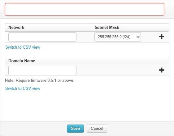
The network group editor. Each entry takes a Network and a Subnet Mask, and the Domain Name section carries its own firmware note. The empty name box at the top is outlined in red until a group name is entered.
Field | Notes |
Name | Text field naming the group |
Network | The subnet address |
Subnet Mask | Dropdown of mask values, each labelled with its prefix length |
Domain Name | Text field for a domain entry |
Note the following:
- The Switch to CSV view button allows entries to be pasted or edited as CSV instead of one row at a time.
- Domain Name entries require firmware 8.5.1 or above, as the note beneath the Domain Name section states.
The Subnet Mask dropdown holds 32 entries, one for every prefix length, from 128.0.0.0 (/1) through 255.255.255.255 (/32). Both single host addresses and large blocks can be entered.
8.3. WAN Configurations
Apply a WAN configuration profile to Balance and MAX devices in the group to set WAN priority, routing mode, health checks, DNS servers and DNS over HTTPS without configuring each device.
Where to find it
Group > Network Settings > WAN Configurations
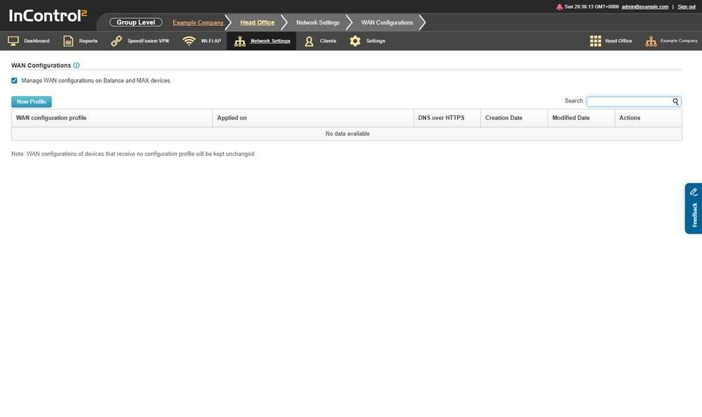
The WAN Configurations screen. The profile list appears when Manage WAN configurations on Balance and MAX devices are selected.
8.3.1. Switching Group Management On
The screen is governed by a single checkbox, Manage WAN configurations on Balance and MAX devices. Before selecting it, see 8.1.1 Before You Tick a Manage Checkbox.
Step | What happens |
Select Manage WAN configurations on Balance and MAX devices | The profile list and its controls appear |
Click Save | InControl 2 asks for confirmation: WAN configurations on ALL Balance and MAX devices in this group will be governed by the profiles below. Are you sure you want to proceed? |
Confirm | WAN configurations on all Balance and MAX devices in the group are governed by the profiles defined here |
Caution: A wrong WAN Priority, Standby State or DNS Servers value in a profile can disconnect every device the profile selects from InControl 2. Before saving, confirm that Auto Roll Back Device Configuration is selected in Group > Settings > InControl Options (13.6.1 Configuration Control), so a device that cannot reach InControl 2 within 10 minutes of receiving a configuration rolls it back.
The confirmation covers every Balance and MAX device in the group (8.1.1 Before You Tick a Manage Checkbox). After saving, see Check that a change arrived (8.1.3 Check That a Change Arrived).
Devices outside every profile are not reset. The page states that WAN configurations of devices that receive no configuration profile will be kept unchanged.
8.3.2. What This Screen Shows
Column | What it shows |
WAN configuration profile | The profile name |
Applied on | Which devices the profile targets |
DNS over HTTPS | The DNS over HTTPS state carried by the profile |
Creation Date | When the profile was created |
Modified Date | When it was last changed |
Actions | Per row actions for that profile |
An empty list shows No data available.
8.3.3. Controls on This Screen
Control | What it does |
Manage WAN configurations on Balance and MAX devices | Switches group level WAN management on or off |
New Profile | Opens the WAN configuration profile editor |
Search | Filters the profile list |
8.3.4. Creating a Profile
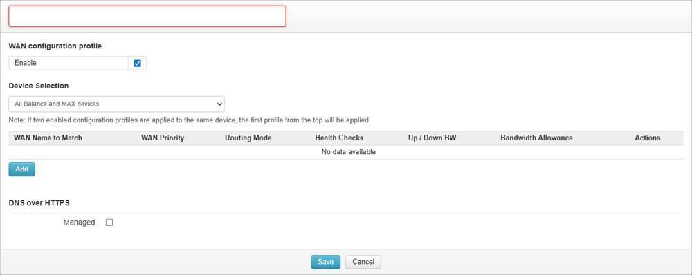
The WAN configuration profile editor. The ordering note under Device Selection applies when a second profile is created.
Field | Notes |
WAN configuration profile | The profile name |
Enable | Turns the profile on or off without deleting it |
Device Selection | Chooses which devices the profile reaches |
Device Selection offers four choices:
- All Balance and MAX devices
- Balance and MAX devices with any of the following tags
- Balance and MAX devices with all of the following tags
- Balance and MAX devices with none of the following tags
If two enabled configuration profiles are applied to the same device, the first profile from the top is applied. Keep tag selections from overlapping.
8.3.5. What a Profile Does and Does Not Change
The information icon beside the screen title explains the model:
- A profile composes multiple WANs' primary settings and applies to devices chosen by tag.
- A profile can hold several WAN setting profiles, each matching WANs by exact name, for example WAN 1 or Cellular.
- Profiles carry primary settings only. Settings not specified in a profile are kept intact, and the tooltip names PPPoE Settings, Wi-Fi WAN Settings and Cellular Settings as examples. A WAN configuration profile is therefore a partial overlay, not a full replacement of a device's WAN configuration.
Inside the profile, WAN entries are added one at a time with the Add button and listed in a grid:
Column | What it holds |
WAN Name to Match | The WAN name the entry applies to on the device |
WAN Priority | The priority assigned to that WAN |
Routing Mode | The routing mode assigned to that WAN |
Health Checks | The health check settings for that WAN |
Up / Down BW | The upload and download bandwidth values |
Bandwidth Allowance | The bandwidth allowance settings |
Actions | Per row actions for that WAN entry |
The entry grid shows No data available until the first WAN entry is added.
8.3.6. DNS over HTTPS
The editor closes with a DNS over HTTPS section governed by a Managed control, which is the setting reported in the DNS over HTTPS column of the profile list. Selecting Managed shows two more controls.
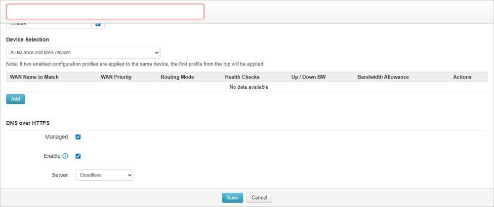
The DNS over HTTPS section with Managed selected, showing the Enable checkbox and the Server list.
Control | What it does |
Enable | Turns DNS over HTTPS on or off for the WANs the profile governs. Selected by default |
Server | Chooses the resolver. Defaults to Cloudflare |
Server offers five choices:
- Cloudflare
- Quad9
- Google DNS
- OpenDNS
- Custom URL:
The Enable tooltip states that the DNS proxy server forwards DNS requests to the selected resolver over an HTTPS connection, and DNS requests are no longer proxied to the UDP based DNS resolvers offered by the WANs. It also says to select Custom URL: and enter the resolver URL and IP addresses.
Managed and Enable are separate settings. Managed sets whether the profile governs the setting. Enable sets its value.
Enable is selected by default. Selecting Managed and saving therefore turns DNS over HTTPS on for every WAN the profile governs. To use the profile to turn the feature off, select Managed and then clear Enable.
Choosing Custom URL:
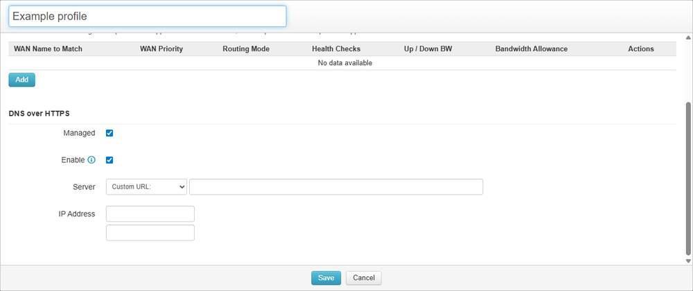
Custom URL: selected, with Managed and Enable ticked. The Server row gains a URL field, with two IP Address fields beneath it.
Selecting Custom URL: adds fields beside and below the dropdown:
Field | Notes |
Server | A URL field, beside the dropdown. This is the resolver's DoH URL |
IP Address | Two fields, for the resolver's addresses |
Enter the resolver URL and at least one IP address.
8.3.7. Adding a WAN Entry
Add opens WAN Settings.
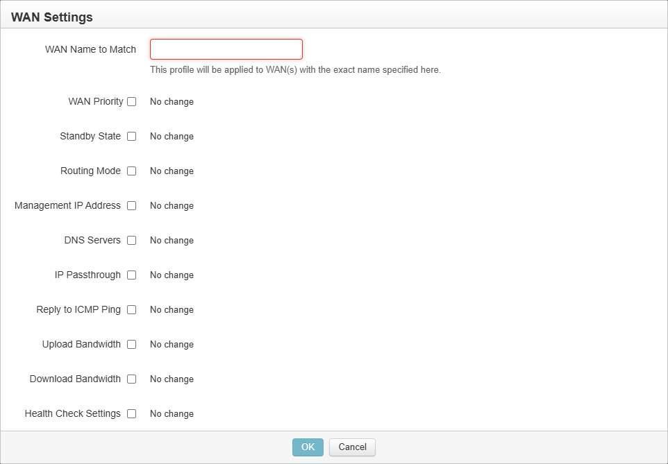
The WAN entry form. Every setting below the name starts at No change.
Field | Notes |
WAN Name to Match | Text field. The form states that the profile will be applied to WANs with the exact name specified here. It is a name, not a port: entries bind to the WAN name as the device reports it, so devices with different WAN naming need either matching names or separate profiles |
WAN Priority | Starts at No change |
Standby State | Starts at No change |
Routing Mode | Starts at No change |
Management IP Address | Starts at No change |
DNS Servers | Starts at No change |
IP Passthrough | Starts at No change |
Reply to ICMP Ping | Starts at No change |
Upload Bandwidth | Starts at No change |
Download Bandwidth | Starts at No change |
Health Check Settings | Starts at No change. Health Checks on all WANs in Group > Settings > InControl Options (13.6.4 The Base Data Usage Calculator) is a display field, not a setting |
Bandwidth Allowance | Starts at No change |
The form closes with OK and Cancel.
Note the following:
- Every setting starts at No change. An entry saved with no changes below the name leaves the device unchanged. Change only the fields to be governed. The rest stay under local control.
- Standby State, Management IP Address, DNS Servers, IP Passthrough and Reply to ICMP Ping are shown in the entry form only. To see their values, reopen the entry.
One entry applies to every selected device. A value set here reaches the WAN of that name on every device the profile selects, so WAN Priority, Standby State and Bandwidth Allowance can be set once rather than device by device.
8.4. Outbound Policy
Define outbound traffic rule sets once at group level and apply them to Balance and MAX devices, so that each kind of traffic uses the same link at every site without configuring outbound policy on each device. Outbound Policy is configured in the interface. It is not available in the InControl API.
Where to find it
Group > Network Settings > Outbound Policy
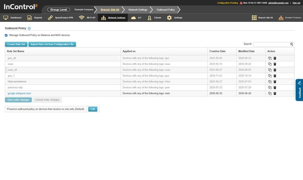
The Outbound Policy screen. The preservation line sits below the rule set list and carries its own Edit button.
8.4.1. Switching Group Management On
The screen is governed by Manage Outbound Policy on Balance and MAX devices. Rule sets defined here take effect on Balance and MAX devices only after that checkbox is selected. Before selecting it, see 8.1.1 Before You Tick a Manage Checkbox.
Step | What happens |
Select Manage Outbound Policy on Balance and MAX devices and click Save | InControl 2 asks for confirmation: Outbound policy rules on ALL Balance and MAX units in this group will be governed by the rule sets below. Are you sure you want to proceed? |
Confirm | Outbound policy rules on all Balance and MAX units in the group are governed by the rule sets defined here |
Caution: A change to outbound policy can leave a device unable to reach InControl 2, and a rule set reaches every device it selects on the same Save. Before saving, confirm that Auto Roll Back Device Configuration is selected in Group > Settings > InControl Options (13.6.1 Configuration Control), so a device that cannot reach InControl 2 within 10 minutes of receiving a configuration rolls it back.
The confirmation covers every Balance and MAX device in the group (8.1.1 Before You Tick a Manage Checkbox). A device that rolls back takes no further configuration from InControl 2 until outbound policy or firewall rules are changed again. After saving, see Check that a change arrived (8.1.3 Check That a Change Arrived).
Caution: Local changes are overwritten. The Bulk Configurator page (13.12.1 What the Page Tells You First) states that where InControl 2's management option is enabled for Outbound Policy, changes made directly on the devices are reverted and overwritten by the settings defined in InControl 2. Make permanent changes here, not in the device web admin. To keep local settings on one site, list it under Disable Device Configuration on in Group > Settings > InControl Options (13.6.1 Configuration Control), which stops InControl 2 making any configuration change to that device.
8.4.2. What This Screen Shows
Column | What it shows |
Rule Set Name | The name given when the rule set was created |
Applied on | Which devices the rule set targets |
Creation Date | When the rule set was created |
Modified Date | When it was last changed |
Action | Per row actions for that rule set |
An empty list shows No data available.
8.4.3. Controls on This Screen
Control | What it does |
Manage Outbound Policy on Balance and MAX devices | Switches group level outbound policy management on or off |
Create Rule Set | Opens the rule set editor |
Import Rule Set from Configuration File | Builds a rule set from a configuration file rather than by hand |
Edit | Opens Preservation of Outbound Policy on Devices |
Search | Filters the rule set list |
8.4.4. Creating a Rule Set
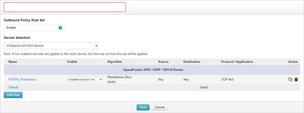
The outbound policy rule set editor. Two rules are already present before any rule is added.
At the top of the editor:
Field | Notes |
Outbound Policy Rule Set | The rule set name |
Enable | Turns this rule set on or off without deleting it |
Device Selection | Chooses which devices the rule set reaches |
Device Selection offers four choices:
- All Balance and MAX devices
- Balance and MAX devices with any of the following tags
- Balance and MAX devices with all of the following tags
- Balance and MAX devices with none of the following tags
When two enabled rule sets reach the same device, the first rule set from the top is applied. Keep rule set targeting from overlapping.
8.4.5. Rules Match WANs by Name
The information icon beside the screen title explains how a rule set is applied to a device:
- A rule set is the entire set of rules as defined on the device's own outbound policy page, at Network > Outbound Policy.
- Each rule applies to a name specific WAN connection, for example WAN 1. Only WAN connections whose names match are imported.
- A rule is not applied to a device that has no WAN with a matching name. This is not an error, and the rest of the rule set still applies. Check WAN names before saving. To enforce traffic to WAN 1, every selected device needs a WAN called WAN 1.
- The same matching applies to SpeedFusion VPN profiles used by the Priority and Enforced algorithms. The rule's SpeedFusion VPN profile name must match a profile name on the device or the rule is excluded.
Because a rule set is defined as the device's entire outbound policy, build it to hold every rule the selected sites need, including any site-specific rules they currently use.
8.4.6. The Rule List
Rules are added with Add Rule and listed in a grid:
Column | What it holds |
Name | The rule name |
Enable | Whether the rule is active |
Algorithm | The outbound algorithm the rule applies |
Source | The source the rule matches |
Destination | The destination the rule matches |
Protocol / Application | The protocol or application the rule matches |
Action | The outbound action taken |
Two entries are present before any rule is added:
Entry | What the editor shows |
SpeedFusion VPN / OSPF / RIPv2 Routes | A fixed first entry, listed above the editable rules |
HTTPS_Persistence | Algorithm Persistence (Src): (Auto), Source Any, Destination Any, Protocol / Application TCP 443, Action Default (Auto) |
Rule rows carry a Clone action, so an existing rule can be copied and adjusted rather than rebuilt.
Enable on HTTPS_Persistence offers Disabled and Enabled (Always on).
8.4.7. Adding a Rule
Add Rule opens the rule form.
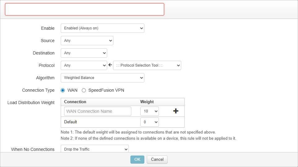
The outbound rule form. Algorithm sits above the load distribution controls that depend on it.
Field | Options |
Name | Text field |
Enable | Disabled, Enabled (Always on) |
Source | Any, IP Address, IP Network, MAC Address, Grouped MAC Addresses, Grouped Network, Client Type, Client's Associated SSID |
Destination | Any, IP Address, IP Network, Domain Name, SpeedFusion VPN Network, Grouped Network, SaaS, Region |
Protocol | Any, TCP, UDP, DSCP, IP |
Algorithm | Weighted Balance, Persistence, Enforced, Priority, Overflow, Least Used, Lowest Latency, Fastest Response Time |
Connection Type | WAN, SpeedFusion VPN, IPsec VPN |
When No Connections are Available | Drop the Traffic, Use Any Available Connections, Fall-through to Next Rule |
Source and Destination both accept the grouped definitions made elsewhere in this chapter. Grouped Network (8.6 Grouped Networks) and Grouped MAC Addresses (8.7 Grouped MAC Addresses) point to the sets defined on those screens. Define those sets first.
Enable offers Disabled and Enabled (Always on). The tooltip states: The schedule is currently disabled on Device Schedule page. This rule will be always on. A time limited outbound rule depends on the Device Schedule page.
Protocol Selection Tool
Beside Protocol is a second dropdown listed as : : Protocol Selection Tool : :. It fills in the protocol for a named service:
HTTP, HTTPS, IMAP, POP3, RDP, SMTP, SSH, Telnet, AOL, Auth, Citrix, DNS, FTP, LDAP, LotusNotes, MS-SQL-Monitor, MS-SQL-Server, NTP, RADIUS, RADIUS-acct, RTSP, SNMP, SNMP-trap, Syslog, Traceroute (Windows).
Load Distribution Weight
- Each connection is given a Connection Weight from 10 down to 0.
- A Default weight, also 10 down to 0, covers everything else. The form states that the default weight will be assigned to connections that are not specified above.
- The form also states that if none of the defined connections is available on a device, this rule will not be applied to it.
When No Connections are Available requires firmware 8 or above. The form states this beneath the setting.
The form closes with OK and Cancel.
8.4.8. Preservation on Removal
The Edit button opens Preservation of Outbound Policy on Devices.
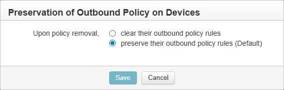
The preservation dialog. Preserve is the default.
Option | Effect |
Upon policy removal, clear their outbound policy rules | The device is left with no outbound policy rules |
Upon policy removal, preserve their outbound policy rules | The device keeps the rules it already had. This is the default |
The list page shows the current state on the line above the button: Preserve outbound policy on devices that receive no rule sets (Default).
The wording mirrors the equivalent setting in Firewall Rules, but the two are separate settings. Changing one does not change the other.
Removing a rule set. Under the default preserve setting, deleting a rule set leaves its rules on the devices. To remove them, set Edit to Upon policy removal, clear their outbound policy rules before deleting, which leaves the devices with no outbound policy rules.
8.5. Firewall Rules
Define firewall policy, including content blocking, once at group level and apply it to every Balance, MAX and FusionHub device in the group. This keeps the same security policy at every site without configuring each device.
Where to find it
Group > Network Settings > Firewall Rules
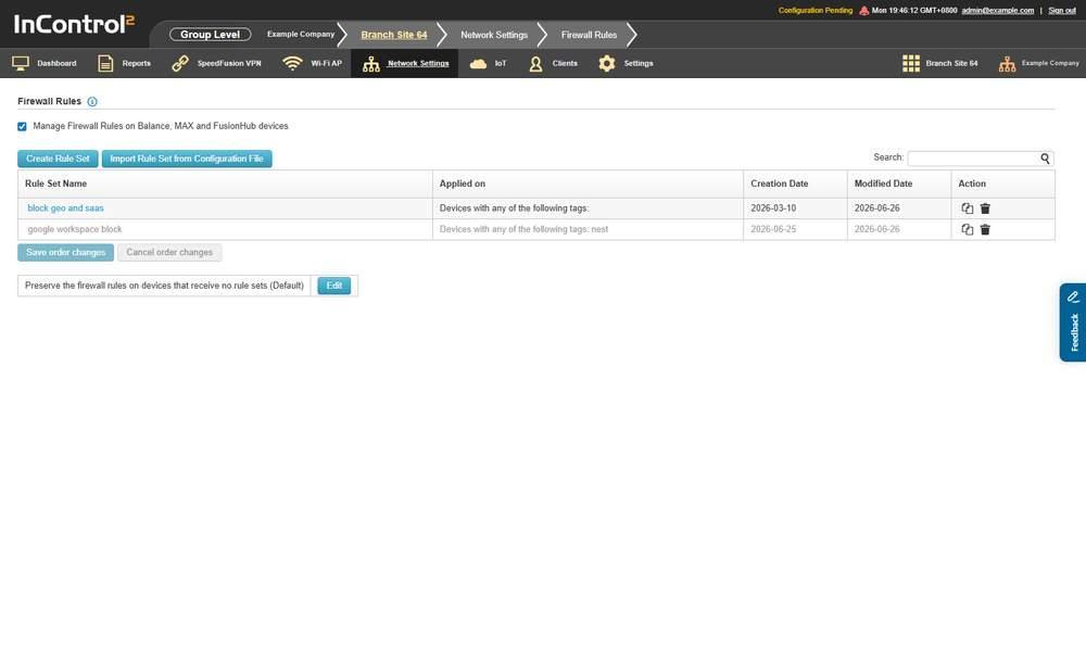
The Firewall Rules screen once group management is switched on. Before that, the page shows only the checkbox at the top.
8.5.1. Switching Group Management On
The screen initially shows a single checkbox. The rule set list, the buttons and the preservation setting are hidden until it is selected. Before selecting it, see 8.1.1 Before You Tick a Manage Checkbox.
Step | What happens |
Select Manage Firewall Rules on Balance, MAX and FusionHub devices | The rule set list and its controls appear |
Click Save | InControl 2 asks for confirmation |
Confirm | Firewall rules on all Balance and MAX units in the group are governed by the rule sets defined here |
Caution: A change to firewall rules can leave a device unable to reach InControl 2, and a rule set reaches every device it selects on the same Save. Before saving, confirm that Auto Roll Back Device Configuration is selected in Group > Settings > InControl Options (13.6.1 Configuration Control), so a device that cannot reach InControl 2 within 10 minutes of receiving a configuration rolls it back.
The confirmation states that the change applies to every Balance and MAX unit in the group, not only to the devices a rule set later targets. A device that rolls back takes no further configuration from InControl 2 until outbound policy or firewall rules are changed again. After saving, see Check that a change arrived (8.1.3 Check That a Change Arrived).
Caution: Local changes are overwritten. The Bulk Configurator page (13.12.1 What the Page Tells You First) states that where InControl 2's management option is enabled for Firewall Rules, changes made directly on the devices are reverted and overwritten by the settings defined in InControl 2. Make permanent changes here, not in the device web admin. To keep local settings on one site, list it under Disable Device Configuration on in Group > Settings > InControl Options (13.6.1 Configuration Control), which stops InControl 2 making any configuration change to that device.
Devices that receive no rule set keep a firewall. By default, they preserve the firewall rules they already have. See Preservation on removal below (8.5.10 Preservation on Removal).
8.5.2. The Rule Set List
Column | What it shows |
Rule Set Name | The name given when the rule set was created |
Applied on | Which devices the rule set targets |
Creation Date | When the rule set was created |
Modified Date | When it was last changed |
Action | Per row actions for that rule set |
An empty list shows No data available.
8.5.3. Controls on This Screen
Control | What it does |
Manage Firewall Rules on Balance, MAX and FusionHub devices | Switches group level firewall management on or off |
Create Rule Set | Opens the rule set editor |
Import Rule Set from Configuration File | Builds a rule set from a configuration file rather than by hand |
Edit | Opens Preservation of Firewall Rules on Devices |
Search | Filters the rule set list |
8.5.4. Creating a Rule Set
Caution: A rule set is defined as the device's entire firewall rule list. A rule set created only to select a Content Blocking category becomes the whole firewall rule list of every device it selects. Build it to hold every rule the selected sites need, including any site specific rules they currently use. See 8.5.5 The Four Rule Groups.
Create Rule Set opens the editor.
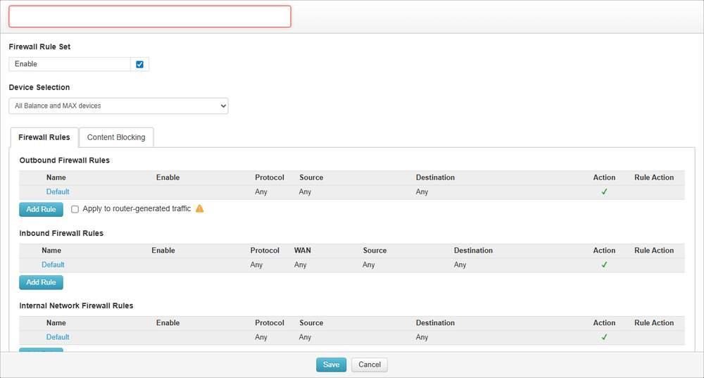
The rule set editor. Rule Set Name is required, and the four rule groups each carry their own Add Rule button.
At the top of the editor:
Field | Notes |
Rule Set Name | Required. The editor marks it in red until filled |
Enable | Turns this rule set on or off without deleting it |
Device Selection | Chooses which devices the rule set reaches |
Device Selection offers four choices:
- All Balance and MAX devices
- Balance and MAX devices with any of the following tags
- Balance and MAX devices with all of the following tags
- Balance and MAX devices with none of the following tags
The three tag-based options make a rule set selective. Tag the devices first, then select the tag in the rule set.
The editor has two tabs, Firewall Rules and Content Blocking.
8.5.5. The Four Rule Groups
The Firewall Rules tab holds four separate rule groups. Each begins with a Default rule set to Any, and each has its own Add Rule button.
Rule group | Columns | Applies to |
Outbound Firewall Rules | Name, Enable, Protocol, Source, Destination, Action, Rule Action | Traffic leaving the network |
Inbound Firewall Rules | Name, Enable, Protocol, WAN, Source, Destination, Action, Rule Action | Traffic arriving from a WAN |
Internal Network Firewall Rules | Name, Enable, Protocol, Source, Destination, Action, Rule Action | Traffic between internal networks |
Local Service Firewall Rules | Name, Enable, Service, WAN, Source, Action, Rule Action | Traffic to services on the device itself |
Note the following:
- Inbound rules add a WAN column. Outbound and internal network rules do not. An inbound rule can therefore be scoped to one WAN connection.
- Local Service Firewall Rules require firmware 8.0.1 or above. The editor states this beneath the group. Devices on older firmware will not receive those rules.
Scoping an inbound rule to a WAN also scopes which devices receive it. The information icon beside the screen title states that when an inbound rule specifies a particular WAN, only devices with a WAN of that name receive the rule, and devices without it are excluded. A rule allowing traffic to WAN 1 reaches only devices that have a WAN called WAN 1. Use consistent WAN names across the group, as for Outbound Policy.
The same tooltip defines a rule set as the entire set of rules as defined on the device's own firewall page, at Network > Firewall > Access Rules. It also states that if a device is selected by more than one rule set, the rule set with the earliest creation date will be applied. See the caution in Creating a rule set (8.5.4 Creating a Rule Set).
Outbound Firewall Rules also has a checkbox, Apply to router-generated traffic. It is cleared by default, so outbound rules do not filter traffic the router itself originates unless it is selected.
8.5.6. Adding a Rule
Each of the four rule groups has its own Add Rule button, and each opens a different form. The form names its rule group along its top edge. Every rule is Allow or Deny. No rule reaches a device until the rule set itself is saved.
On all four forms, Enable offers Disabled and Enabled (Always on). The tooltip states: The schedule is currently disabled on Device Schedule page. This rule will be always on. A firewall rule that applies only at certain times depends on the Device Schedule page.
Outbound Firewall Rules
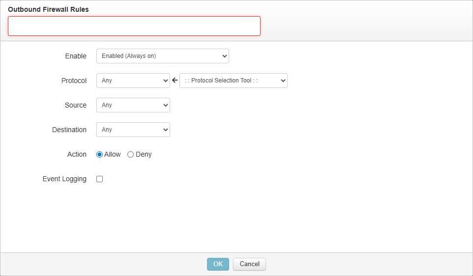
The rule form for the Outbound Firewall Rules group. Action and Event Logging sit at the bottom.
Field | Options |
Name | Text field |
Enable | Disabled, Enabled (Always on) |
Protocol | Any, TCP, UDP, ICMP, DSCP, IP |
Source | Any, IP Address, IP Network, MAC Address, Grouped Network, Grouped MAC Addresses, Client Type |
Destination | Any, IP Address, IP Network, Domain Name, Grouped Network, SaaS, Region |
Action | Allow, Deny |
Event Logging | Records matches of this rule |
The Protocol Selection Tool dropdown beside Protocol fills in a named service: HTTP, HTTPS, IMAP, POP3, RDP, SMTP, SSH, Telnet, Ping Echo, Ping Echo Reply, Any ICMP Types, AOL, Auth, Citrix, DNS, FTP, LDAP, LotusNotes, MS-SQL-Monitor, MS-SQL-Server, NTP, RADIUS, RADIUS-acct, RTSP, SNMP, SNMP-trap, Syslog, Traceroute (Windows). All three forms that carry a Protocol field offer the same 28 services.
Inbound Firewall Rules
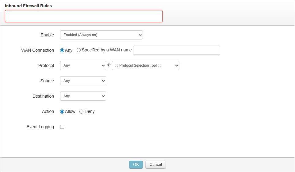
The inbound rule form. WAN Connection sits between Enable and Protocol. The other three forms do not have this field.
Field | Options |
Name | Text field |
Enable | Disabled, Enabled (Always on) |
WAN Connection | Any, or Specified by a WAN name with a text field for the name |
Protocol | Any, TCP, UDP, ICMP, DSCP, IP |
Source | Any, IP Address, IP Network, Grouped Network, SaaS, Region, Client Type |
Destination | Any, IP Address, IP Network, Grouped Network |
Action | Allow, Deny |
Event Logging | Records matches of this rule |
Selecting Specified by a WAN name shows a text field. The name must match the WAN name on the device. Devices with no WAN of that name do not receive the rule, as described above.
Source and destination options differ from the outbound form:
- Inbound rules can match SaaS and Region as a source, which the outbound form only offers as a destination.
- Inbound rules cannot match a MAC Address or a Grouped MAC Addresses set, and cannot use a Domain Name as the destination.
Internal Network Firewall Rules
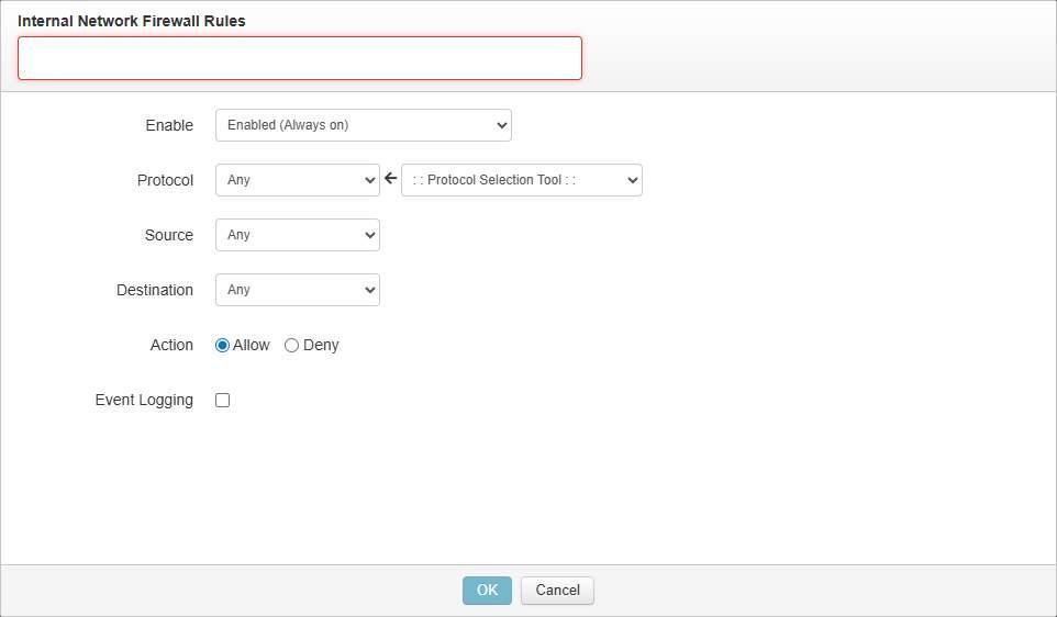
The internal network rule form. Its field list matches the outbound form except for the destination choices.
Field | Options |
Name | Text field |
Enable | Disabled, Enabled (Always on) |
Protocol | Any, TCP, UDP, ICMP, DSCP, IP |
Source | Any, IP Address, IP Network, MAC Address, Grouped Network, Grouped MAC Addresses, Client Type |
Destination | Any, IP Address, IP Network, Domain Name, Grouped Network |
Action | Allow, Deny |
Event Logging | Records matches of this rule |
This form matches the outbound form field for field, with one exception: SaaS and Region are absent from Destination. Both describe internet destinations, so neither applies to traffic between internal networks.
Local Service Firewall Rules
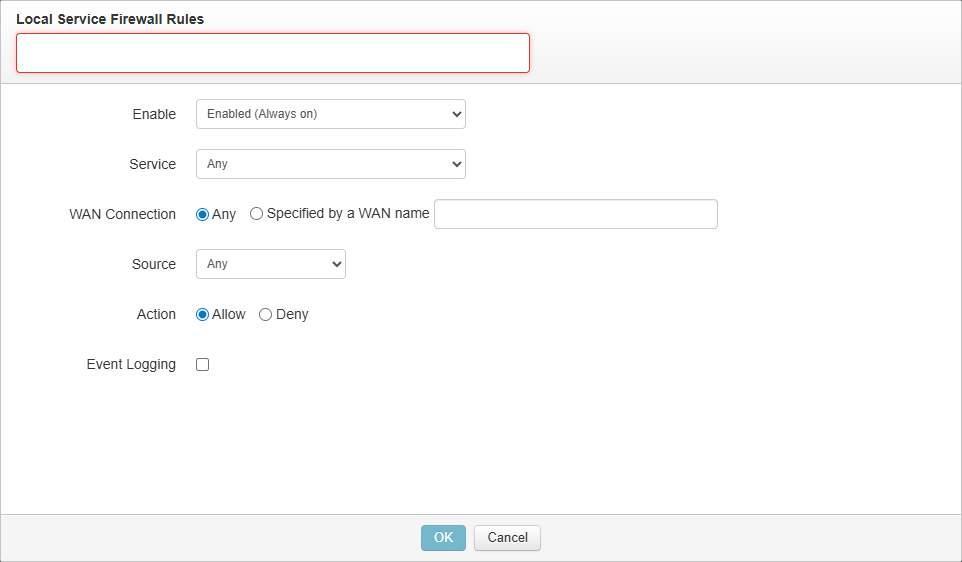
The local service rule form. Service replaces Protocol, and there is no Destination because the device itself is the destination.
Field | Options |
Name | Text field |
Enable | Disabled, Enabled (Always on) |
Service | Any, SpeedFusion VPN handshake port, SpeedFusion VPN data port, Web Admin Access, DNS Server, SNMP Server |
WAN Connection | Any, or Specified by a WAN name with a text field for the name |
Source | Any, IP Address, IP Network, Client Type |
Action | Allow, Deny |
Event Logging | Records matches of this rule |
This form differs from the other three:
- Service replaces Protocol. Select the protected service on the device, not a transport protocol. There is no Protocol Selection Tool.
- There is no Destination. The device itself is the destination, so only the source is specified.
- Source is the shortest list of the four. Any, IP Address, IP Network and Client Type only. Grouped Networks and MAC-based matching are not available here.
- Web Admin Access is one of the services. A Deny rule matching it can lock administrators out of the device's own web interface. Restrict the source before using it.
The four forms compared
Field | Outbound | Inbound | Internal Network | Local Service |
WAN Connection | no | yes | no | yes |
Protocol | yes | yes | yes | Service instead |
Protocol Selection Tool | yes | yes | yes | no |
Source choices | 7 | 7 | 7 | 4 |
Destination choices | 7 | 4 | 5 | none |
Event Logging is per rule. It is separate from the Logging control in Intrusion Detection and DoS Prevention. Enabling one does not enable the other. It appears on all four forms.
Firewall rules and outbound policy rules look alike, but their choices differ in four places. The comparison below uses the outbound firewall rule form:
Field | Firewall rule | Outbound policy rule |
Protocol | Includes ICMP | No ICMP |
Protocol Selection Tool | Includes Ping Echo, Ping Echo Reply and Any ICMP Types | Those three are absent |
Source | No Client's Associated SSID | Adds Client's Associated SSID |
Destination | No SpeedFusion VPN Network | Adds SpeedFusion VPN Network |
Every form closes with OK and Cancel. The rule set itself must still be saved.
8.5.7. Intrusion Detection and DoS Prevention
The editor includes an Intrusion Detection and DoS Prevention section with two controls, Enable and Logging. Logging is separate from enabling, so detection can run with or without a log being kept.
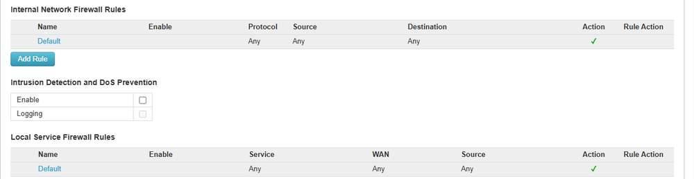
Intrusion Detection and DoS Prevention with its Enable and Logging checkboxes, between Internal Network Firewall Rules and Local Service Firewall Rules.
The section sits between Internal Network Firewall Rules and Local Service Firewall Rules.
8.5.8. The Content Blocking Tab
The tab blocks applications by name, or websites by category with a preset or Custom.
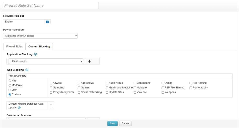
The Content Blocking tab inside the rule set editor. Application Blocking sits at the top, above the category list and the customized domain entries.
Content Blocking is a tab inside the firewall rule set editor. It is not an item in the Network Settings menu. Content Blocking applies through the rule set, so it inherits the rule set's Device Selection. There is no separate device targeting for content blocking.
Application Blocking
- A single dropdown that opens on Please Select....
- It lists 393 entries in total, organised into twelve blocks. Each block begins with an entry that selects the whole block, followed by the individual applications in it.
Block selector | Examples of what follows it |
All Supported Streaming Applications | Netflix, Spotify, Twitch, Youtube |
All Database Applications | MongoDB, MySQL, Oracle, PostgreSQL |
All Email Protocols | Gmail, IMAP, POP3, SMTP |
All Supported File Sharing / Transfer Applications | Bittorrent, DropBox, FTP, Google Drive |
All Supported IM Applications | Messenger, Signal, Telegram, WhatsApp |
All Supported Gaming Applications | Epic Games, Roblox, Steam, Xbox |
All Supported Miscellaneous Protocols | Captive Portal, DHCP, DNS, HTTP, NTP, SNMP |
All Supported Peer-to-Peer Applications | eMule/eDonkey, Gnutella, XunLei/Thunder |
All Supported Remote Access Applications | Anydesk, Remote Desktop, SSH, TeamViewer |
All Supported Security/Tunneling Protocols | IPsec, OpenVPN, Tor, WireGuard |
All Supported VoIP Protocols | SIP, Skype, Webex, Zoom |
All Supported Web Applications | Facebook, GitHub, Microsoft Office 365, TikTok |
Use the block selector to block a whole class. Select individual entries to leave part of a class allowed.
Captive Portal appears here as an application. In the Miscellaneous Protocols block it names the detected protocol, not the Captive Portals feature described later in this chapter (8.14 Captive Portals). Blocking it does not disable a configured portal.
Web Blocking
Below Application Blocking is Web Blocking, which works by category rather than by application. The two are independent: Application Blocking matches the traffic itself, and Web Blocking matches the site category. It has a Preset selector with four settings:
- High
- Moderate
- Low
- Custom
Presets are a shortcut for the category list beneath them. Select Custom for a combination the three named presets do not produce.
Web Blocking lists 17 categories:
- Adware
- Aggressive
- Audio-Video
- Contraband
- Dating
- File Hosting
- Gambling
- Games
- Health and Medicine
- Malware
- P2P/File Sharing
- Pornography
- Proxy/Anonymizer
- Social Networking
- Update Sites
- Violence
- Weapons
Note the following about this list:
- All 17 appear regardless of the licence tier on the device. A device with the Lite tier of web content filtering still enforces only its 6 categories, because the device firmware applies the tier. Selecting all 17 on a group containing Lite devices does not extend what those devices block.
- Contraband is Abused Drugs on the device. The category InControl 2 labels Contraband appears in the device web interface as Abused Drugs. The two names refer to the same category.
Content Filtering Database Auto Update
A separate control beneath the category list. Category matching uses a database on the device, and this control keeps it current.
Customized and exempted entries
The tab closes with four sections that adjust the category result. The exemption lists apply to Web Blocking only.
Section | What it takes |
Customized Domains | Domains to block in addition to the selected categories. Carries Switch to CSV view |
Exempted Domains from Web Blocking | Domains to allow through regardless of category. Carries Switch to CSV view |
Exempted User Groups | Three checkboxes: Manager Exempt, Staff Exempt, Guest Exempt |
Exempted Subnets | A Network address plus a Subnet Mask dropdown running 128.0.0.0 (/1) through 255.255.255.255 (/32) |
Note the following:
- Exemption is available three ways. By domain, by user group and by subnet. Use the exemption lists before relaxing a category, because a category relaxed at group level is relaxed for every device the rule set reaches.
- Exempted User Groups names three fixed groups. Manager, Staff and Guest are the only user groups offered here.
Content Blocking Logging
The tab ends with a Content Blocking Logging section with a Logging control. It governs logging for this rule set's content blocking and is separate from the Secure DNS Logging setting on the VLAN Networks screen (8.8.5 Secure DNS Logging).
Blocked requests are listed per device at Device > Reports > Content Blocking Log. See Device Reports, 15.11 Content Blocking Log.
8.5.9. Which Content Filter to Use
The group offers two separate content filters. The following table compares them.
Content Blocking (firewall rule set) | Content filtering on a VLAN | |
Where it is set | The Content Blocking tab of a firewall rule set | The VLAN editor in VLAN Networks |
Scope | Devices chosen by the rule set's Device Selection | One VLAN, on the devices Apply to selects |
Categories | 17, plus Application Blocking | 156, including CIPA Filter and Security threats |
Notes on the screen | Lite tier devices enforce only 6 categories | Secure DNS on the VLAN requires any Care plan and firmware 8.6.0 or above |
Exemptions | By domain, user group and subnet | No exemption lists in the editor |
Logging | Content Blocking Logging in the rule set | Secure DNS Logging on the VLAN Networks list page |
Both are recorded in the device level Content Blocking Log, where Type separates Application and Web blocking from PrimeCare Secure DNS.
8.5.10. Preservation on Removal
The Edit button opens Preservation of Firewall Rules on Devices, which decides what happens to a device when a rule set stops applying to it.
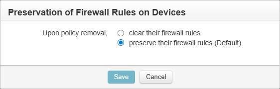
The preservation dialog. Upon policy removal offers two choices, and preserve their firewall rules is marked as the default.
Option | Effect |
Upon policy removal, clear their firewall rules | The device is left with no firewall rules |
Upon policy removal, preserve their firewall rules | The device keeps the rules it already had. This is the default |
Clearing rules on removal can leave a device unprotected.
Caution: Deleting a rule set does not restore a device's earlier local rules. While Preserve the firewall rules on devices that receive no rule sets is selected, a device whose rule set is deleted keeps the rules InControl 2 last pushed to it. The rules it held before InControl 2 managed its firewall are not restored.
Removing a rule set. Under the default preserve setting, deleting a rule set leaves its rules on the devices. To remove them, do one of the following:
- 1.Set Edit to Upon policy removal, clear their firewall rules before deleting. The devices are left with no firewall rules.
- 2.Create a rule set for the same devices holding only the Default rules, with nothing selected on the Content Blocking tab, save it, then delete it. The devices are left with the Default rules only.
8.6. Grouped Networks
Define named sets of networks and domains for this group, so that firewall and outbound rules can reference a name rather than a list of subnets. This screen and Organization-wide Grouped Networks (8.2 Organization-wide Grouped Networks) use the same editor, including the same 32 entry mask list. The difference is scope. A group defined here belongs to this group only, while one defined at organization level is available in all groups.
Where to find it
Group > Network Settings > Grouped Networks
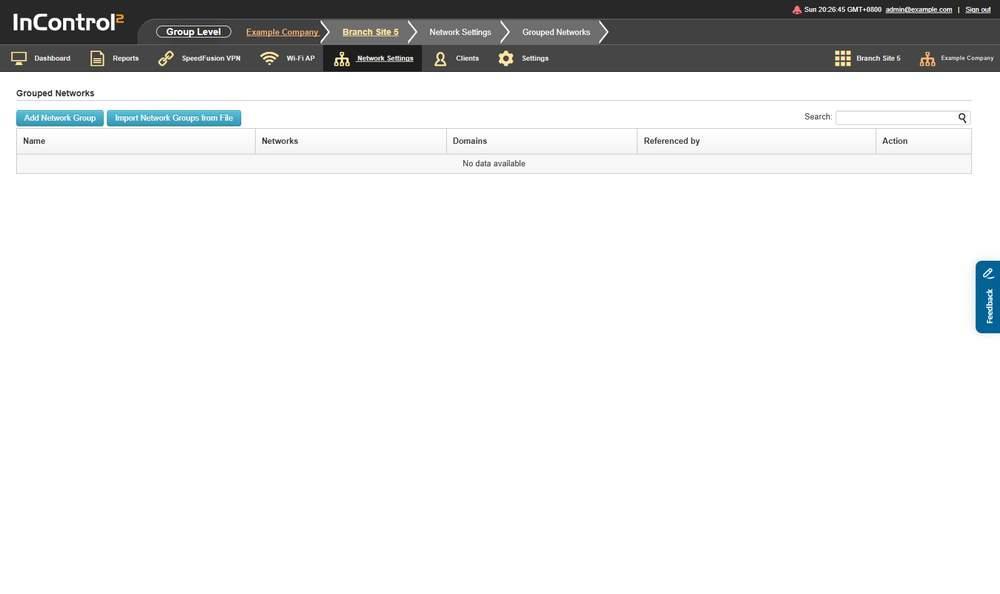
The group level list of network groups. The Referenced by column shows where a group is already in use.
8.6.1. What This Screen Shows
Column | What it shows |
Name | The name given to the network group |
Networks | The subnets the group contains |
Domains | The domain names the group contains |
Referenced by | Where the group is currently used |
Action | Per row actions for that network group |
An empty list shows No data available.
Check Referenced by before editing or deleting a group. It shows which rules depend on the definition.
8.6.2. Controls on This Screen
Control | What it does |
Add Network Group | Opens the network group editor |
Import Network Groups from File | Builds network groups from a file rather than by hand |
Search | Filters the list |
8.6.3. Adding a Network Group
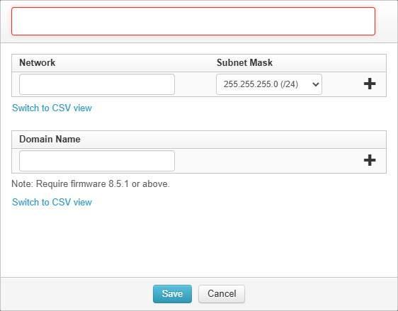
The group level network group editor. It is the same editor as the organization level one, including the Switch to CSV view button.
Field | Notes |
Name | Text field naming the group |
Network | The subnet address |
Subnet Mask | Dropdown of 32 entries, 128.0.0.0 (/1) through 255.255.255.255 (/32) |
Domain Name | Text field for a domain entry |
- Switch to CSV view turns the entry list into a CSV block for bulk editing.
- The dialog shows Note: Require firmware 8.5.1 or above. beneath the Domain Name section.
8.7. Grouped MAC Addresses
Define named sets of MAC addresses for this group, so that other screens can reference the set by name. Groups defined here are referenced in three places elsewhere in this chapter: the Allowed Grouped MAC Addresses dropdown in Captive Portals (8.14.4 Captive Portal Settings), and the Grouped MAC Addresses source option in both firewall rules and outbound policy rules. Define the groups here before using those options.
Where to find it
Group > Network Settings > Grouped MAC Addresses
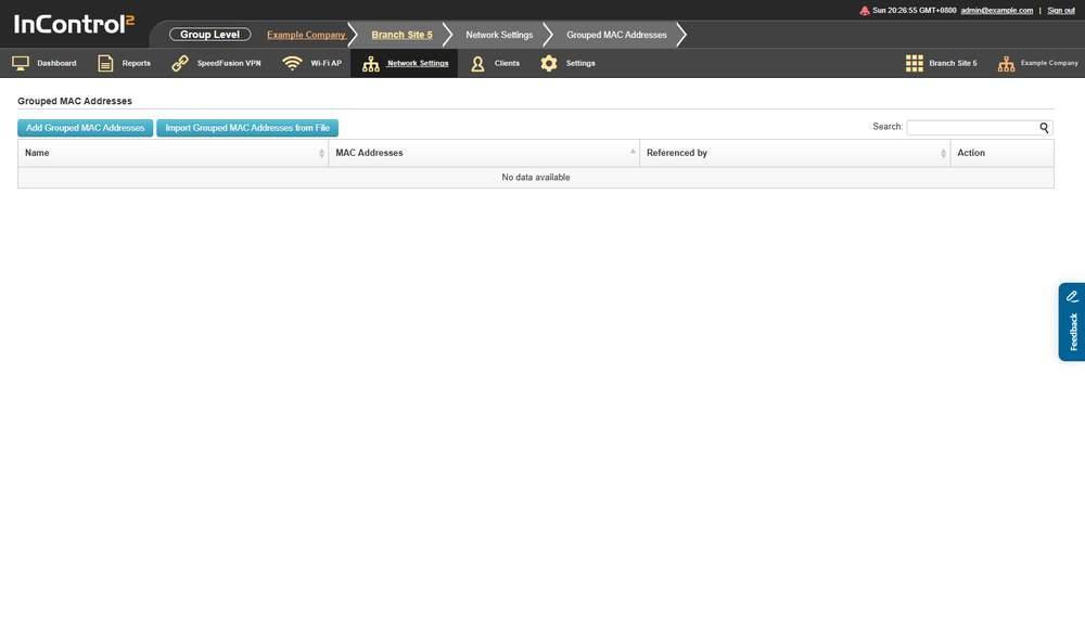
The list of MAC address groups. The Referenced by column shows which features already use each group.
8.7.1. What This Screen Shows
Column | What it shows |
Name | The name given to the MAC address group |
MAC Addresses | The addresses the group contains |
Referenced by | Where the group is currently used |
Action | Per row actions for that group |
An empty list shows No data available.
8.7.2. Controls on This Screen
Control | What it does |
Add Grouped MAC Addresses | Opens the MAC address group editor |
Import Grouped MAC Addresses from File | Builds MAC address groups from a file rather than by hand |
Search | Filters the list |
8.7.3. Adding a MAC Address Group
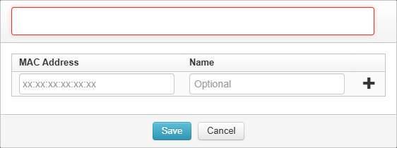
The MAC address group editor. Each entry pairs a MAC Address with a Name of its own.
The editor has three text fields and closes with Save and Cancel:
Field | What it holds |
Group name | The name the group appears under in the list |
MAC Address | The address of one entry |
Name | A label for that individual entry |
The list columns mirror this. Name shows the group and MAC Addresses shows its members. A single group holds many addresses, and each address keeps its own label.
8.8. VLAN Networks
Define the VLAN networks that InControl 2 applies across the group, including their addressing, DHCP behaviour and Secure DNS, so that every site uses the same networks.
Where to find it
Group > Network Settings > VLAN Networks
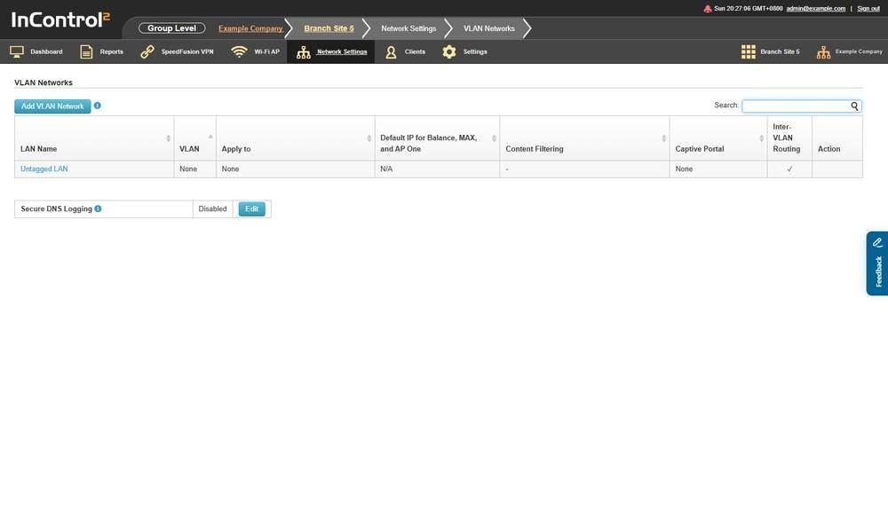
The VLAN network list. Note the Untagged LAN row, which is present before any VLAN is added.
8.8.1. What This Screen Shows
Column | What it shows |
LAN Name | The name of the network |
VLAN | The VLAN ID, or None for the untagged LAN |
Apply to | Which devices the network is applied to |
Default IP for Balance, MAX, and AP One | The default IP address assigned on those product families |
Content Filtering | The content filtering setting for the network |
Captive Portal | The captive portal attached to the network |
Inter-VLAN Routing | Whether routing between VLANs is permitted |
Action | Per row actions for that network |
Content Filtering, Captive Portal and Inter-VLAN Routing are properties of the individual network, not of the group. Each row can differ.
An Untagged LAN row is present before any VLAN is defined. In its initial state, its VLAN is None and its Apply to is None.
A page level Secure DNS Logging setting appears below the network rows, with its own state and its own Edit button.
8.8.2. What InControl 2 Controls and What It Leaves Alone
The information icon beside the list explains which settings InControl 2 controls:
Behaviour | What the tooltip states |
Managed attributes | InControl controls the Name, Inter-VLAN Routing option and Captive Portal settings of every VLAN network defined here |
IP settings | Their IP settings on devices are kept intact |
Removal | Removing a VLAN network here removes it from devices as well |
Creation | A VLAN network not present on a device is created on that device |
Balance and MAX | VLAN networks defined on a Balance or MAX are overwritten by those defined on InControl |
SD Switches | VLAN networks on SD Switches are two way synchronized and InControl managed. One defined on an SD Switch but not on InControl is imported into InControl, then reapplied to every SD Switch in the same group |
Note the following:
- Defining a VLAN here is destructive on Balance and MAX. A VLAN of the same name on the device is overwritten. On SD Switches, synchronization is two way, so a VLAN created locally on one switch is applied to every switch in the group after InControl imports it.
- IP settings are the exception. Everything else in the list is governed from here, but addressing on the device is left as it is. See the Default IP Address note below.
- There is no gate on this screen, and deletion reaches devices. Saving a VLAN network sends it to every device that Apply to selects. Deleting one removes it from all of those devices. Narrow Apply to with a tag before deleting a network that only some sites should lose.
The tooltip recommends creating and managing VLAN networks on InControl 2 rather than on individual devices.
8.8.3. Controls on This Screen
Control | What it does |
Add VLAN Network | Opens VLAN Network Settings |
Edit | Opens Secure DNS Logging |
Search | Filters the list |
8.8.4. VLAN Network Settings
Complete General (Name, VLAN ID, Apply to) first, then the Balance and MAX, DHCP and Secure DNS sections. Saving sends the network to every device that Apply to selects.
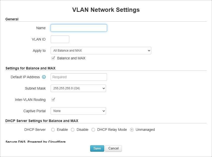
The VLAN editor. It is divided into General, Balance and MAX settings, DHCP and Secure DNS sections.
General
Field | Notes |
Name | The network name |
VLAN ID | Numeric field for the VLAN tag |
Apply to | Chooses which devices receive the network |
Apply to offers three choices:
- All Balance and MAX
- Balance and MAX with any of the following tags:
- Balance and MAX with none of the following tags:
Settings for Balance and MAX
Field | Notes |
Default IP Address | The address the network uses on Balance and MAX devices. Applied on creation only, see below |
Subnet Mask | Dropdown of mask values, 128.0.0.0 (/1) through 255.255.255.252 (/30) |
Inter-VLAN Routing | Controls routing between this VLAN and others |
Captive Portal | Attaches a portal defined in Captive Portals. Shows None when no portal is selected. A captive portal can be attached in two ways. The Captive Portals list reports both SSIDs applied on and VLANs applied on. This field sets the VLAN side |
Default IP Address applies once, at creation. The information icon beside the field states that the address will only be applied when the VLAN is newly created on a device. Editing it later does not re-address devices that already have the VLAN, consistent with the list page tooltip stating that IP settings on devices are kept intact. Plan addressing before the first save.
DHCP Server Settings for Balance and MAX
Field | Options |
DHCP Server | Enable, Disable, DHCP Relay |
Mode | Unmanaged |
DHCP Option 82 | Adds the device's own details to DHCP requests it forwards |
DHCP Option 82 embeds the device MAC address and the network name. The editor states that the feature includes device information as a relay agent for the attached client when forwarding DHCP requests from a DHCP client to a DHCP server, and that the device MAC address and network name are embedded into the circuit ID and remote ID of option 82.
DHCP reservations take an IP suffix, not a full address. Because a reservation made here reaches devices in the group on different subnets, the value is combined with each device's VLAN subnet address before it is applied. On a VLAN with a 192.168.30.0/24 subnet, the suffix 10 is applied as 192.168.30.10. On a /24 network, enter the last octet only, for example 10. The suffix must fall inside the VLAN's subnet.
Secure DNS, Powered by Cloudflare
- The section has a single control, Enable Secure DNS.
- The editor shows two notes. Note 1 states that the feature is only available to devices under any Care plan and running firmware 8.6.0 or above. Both conditions apply, so an in warranty device on older firmware will not use it.
- Note 2 states that all selected devices on this VLAN will utilize Cloudflare's DoH service for all DNS resolutions regardless of their eligibility of the service, and that the DoH service to fall back to can be chosen from a link the note labels HERE.
Eligibility does not filter devices. The setting reaches every selected device on the VLAN whether or not that device is eligible. The fallback choice behind the HERE link sets what ineligible devices do instead.
Content filtering categories
The dialog also shows a content category list of its own. The Content Filtering column on the list page shows the setting of each network.
This is a separate and larger taxonomy than the 17 category Web Blocking list in Firewall Rules > Content Blocking (8.5.8 The Content Blocking Tab). The two lists are not the same. The dialog holds 156 categories: 30 parents and 126 sub-categories, each with its own description. None are selected by default.
Beyond content policy, the Security threats parent covers domains for malware, phishing, command and control and botnet traffic, cryptomining and DNS tunneling. When selected on a VLAN, it applies to every device that Apply to selects for that VLAN, with no setup on each device.
Parent category | What it covers | Sub-categories |
Ads | Sites that are providing ads for websites | Advertisements |
Adult Themes | Pornography, nudity, sexuality and other adult themes | Adult Themes, Nudity, Pornography |
Blocked by Default | Sites that should be blocked by default, and whose sub-categories should not be displayed | Child Abuse |
Business & Economy | Business, economy, finance, education, science and technology | Brokerage & Investing, Business, Cryptocurrency, Economy & Finance, Personal Finance |
CIPA | Aiding schools and organizations in abiding by CIPA requirements | CIPA Filter |
Education | Educational content not covered by Science, Technology or Educational institutions | Education, Educational Institutions, Reference, Science, Space & Astronomy |
Entertainment | Entertainment not covered by the more specific categories | 17, including Audio Streaming, Video Streaming, Gaming, Movies, Music, News & Media, Television |
Gambling | Sites that facilitate online gambling | Gambling |
Government & Politics | Government and politics | Charity and Non-profit, Government/Legal, Politics, Advocacy, and Government-Related |
Health | Health and fitness information | Health & Fitness, Sex Education |
Information Technology | Information technology | none |
Internet Communication | Communication tools such as chat and mail | 10, including Chat, Forums, Instant Messengers, Internet Phone & VOIP, P2P, Webmail |
Job Search & Careers | Searching for jobs and careers | Job Search & Careers |
Military & Weapons | Militaries and weapons | Military, Weapons |
Miscellaneous | Sites not included in the listed security and content categories | Login Screens, Miscellaneous, No Content, URL Alias/Redirect, Unreachable |
Questionable Content | Hacking, piracy, profanity and other questionable activities | 8, including Drugs, Hacking, Hate & Extremism, Profanity, School Cheating, Unreliable Information |
Real Estate | Real estate | Real Estate |
Religion | Religion, alternative religion, religious teachings and groups, spirituality | Religion & Spirituality |
Safe for Kids | Sites that are safe for kids to visit | Safe for Kids |
Security Risks | Not confirmed malicious, but a higher likelihood of containing security threats | New Domains, Newly Seen Domains, Parked & For Sale Domains |
Security threats | Malware, phishing, scam, cryptomining and other security threats | 13, including Command and Control & Botnet, Cryptomining, DGA Domains, DNS Tunneling, Malware, Phishing, Private IP Address, Spam, Spyware |
Shopping & Auctions | Ecommerce, coupons, shopping, auctions and marketplaces | Auctions & Marketplaces, Coupons, Ecommerce, Shopping |
Social & Family | Society and lifestyle | none |
Society & Lifestyle | Lifestyle not covered by the more specific categories | 21, including Alcohol, Dating & Relationships, Fashion, Food & Drink, Social Networks, Tobacco |
Sports | Sports and recreation | Sports |
Technology | Technology not covered by the science category | 12, including APIs, Artificial Intelligence, File Sharing, Remote Access, Search Engines, Translator |
Travel | Listings, reservations and services for travel | Travel |
Vehicles | Vehicles and automobiles, including news, reviews and hobbyist information | Vehicles |
Violence | Sites displaying or promoting violent content | Violence |
Weather | Weather | Weather |
Note the following about this list:
- Information Technology and Social & Family are selected as a whole. Neither has sub-categories.
- Several categories match on the domain rather than on its content. Under Security Risks: domains registered very recently, domains resolved for the first time, and domains that are parked or for sale. Under Security threats: Private IP Address, for domains resolving to private or unreachable addresses. Selecting these categories also blocks newly registered legitimate domains.
- No category is selected when the dialog opens. Content filtering on a new VLAN network is off until categories are selected.
8.8.5. Secure DNS Logging
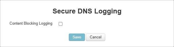
The Secure DNS Logging dialog, opened from the Edit button on the list page.
The dialog has one control, Content Blocking Logging, with Save and Cancel.
The information icon beside the setting states that when it is enabled, blocking logs can be found on the device level Content Blocking Log page, and that Secure DNS is enabled in the VLAN networks above.
Logging is a page level setting. Enabling it applies to Secure DNS logging on every VLAN network on this screen. The logs are viewed at device level.
8.9. LAN Network Settings
Group LAN settings such as static routes, DNS proxy records and Bonjour forwarding into profiles and apply each profile to a selection of devices.
Where to find it
Group > Network Settings > LAN Network Settings
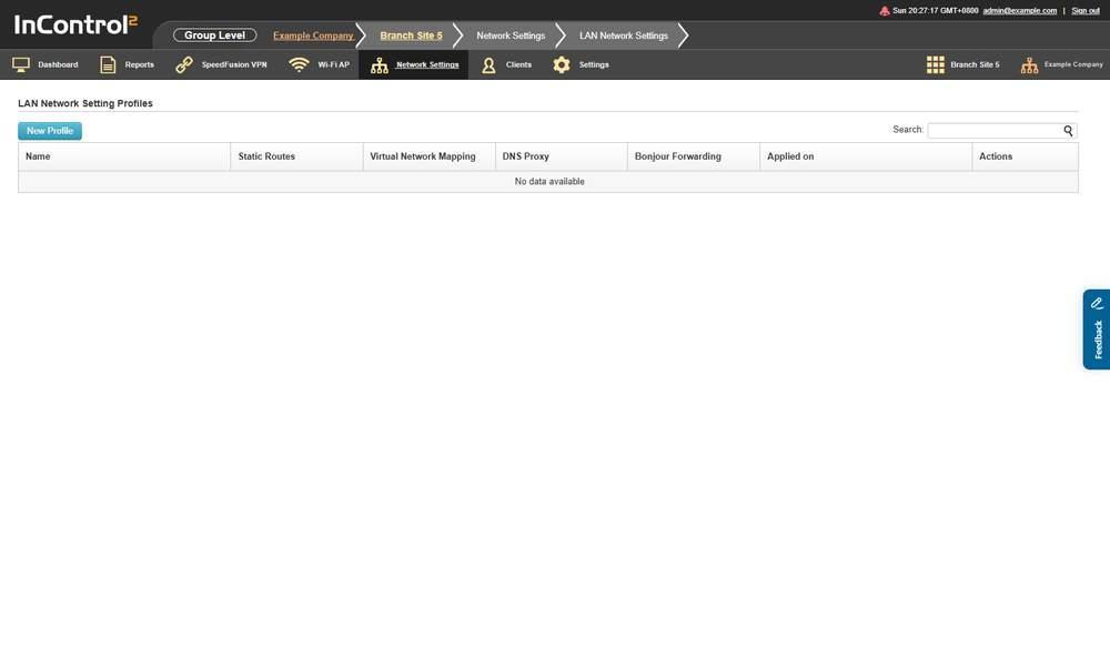
The profile list. Each column reports whether a given LAN feature is carried by that profile.
The page is headed LAN Network Setting Profiles.
8.9.1. What This Screen Shows
Column | What it shows |
Name | The profile name |
Static Routes | The static route content of the profile |
Virtual Network Mapping | The virtual network mapping content of the profile |
DNS Proxy | The DNS proxy content of the profile |
Bonjour Forwarding | The Bonjour forwarding content of the profile |
Applied on | Which devices the profile targets |
Actions | Per row actions for that profile |
An empty list shows No data available.
The four feature columns correspond one to one with the four feature tabs, so the list shows which tabs a profile manages without opening it.
8.9.2. Controls on This Screen
Control | What it does |
New Profile | Opens the LAN network setting profile editor |
Search | Filters the profile list |
8.9.3. Creating a Profile
New Profile opens an editor with five tabs. The four tabs after General match the four feature columns in the profile list.
Tab | What it holds |
General | Name and Device Selection |
Static Routes | A Managed control, then the route table. See Static Routes below |
Virtual Network Mapping | A Managed control, then the mapping table. See Virtual Network Mapping below |
DNS Proxy | A Managed control, then the DNS proxy settings. See DNS Proxy below |
Bonjour Forwarding | A Managed control, then the Bonjour service table. See Bonjour Forwarding below |
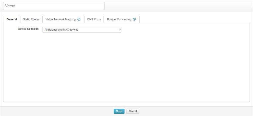
The General tab, holding the profile name and Device Selection.
On the General tab, Device Selection offers four choices:
- All Balance and MAX devices
- Balance and MAX devices with any of the following tags
- Balance and MAX devices with all of the following tags
- Balance and MAX devices with none of the following tags
Each feature is opted into separately. The four feature tabs each open with their own Managed control, so a profile governs only the features whose tabs are managed. Leaving a tab unmanaged leaves that feature under local control on the device rather than clearing it. Before selecting Managed on a tab, see 8.1.1 Before You Tick a Manage Checkbox.
Two of the tabs have an information icon explaining what the feature is for:
Tab | What the tooltip states |
Virtual Network Mapping | Resolves a network address conflict with remote peers, where SpeedFusion VPN, IPsec VPN and IP Forwarding WAN all count as remote connections. The tooltip adds a warning: OSPF and RIPv2 settings should be updated as well, to avoid advertising conflicted networks |
Bonjour Forwarding | Bonjour is Apple's zero configuration networking protocol, normally confined to the local Layer 2 domain. Bonjour forwarding redirects it from one Layer 3 domain to another so devices on other domains can also be discovered |
Virtual Network Mapping requires a related change. The tooltip states that route advertisement must be updated as well. A mapping made here without a matching change on Route Advertisement can advertise the conflicting networks the mapping is meant to resolve.
8.9.4. What Each Feature Tab Manages
A tab takes effect only after Managed is selected. Until then the tab shows only the checkbox. Selecting it shows the feature's settings, described in the four sections below. A tab left unmanaged stays under local control on the device (8.9.3 Creating a Profile).
Static Routes
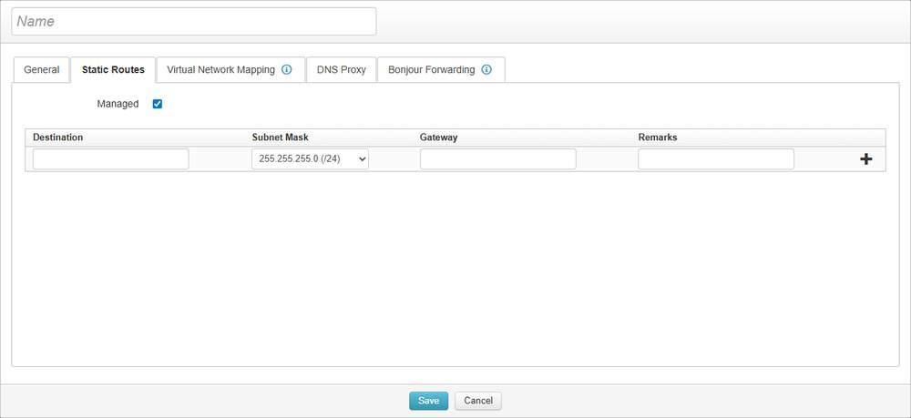
The Static Routes tab with Managed selected, showing the four route columns.
A route table with four columns:
Column | What it takes |
Destination | The destination network address |
Subnet Mask | A dropdown running 0.0.0.0 (/0) through 255.255.255.255 (/32), all 33 prefixes |
Gateway | The next hop for that destination |
Remarks | A free text note |
Virtual Network Mapping
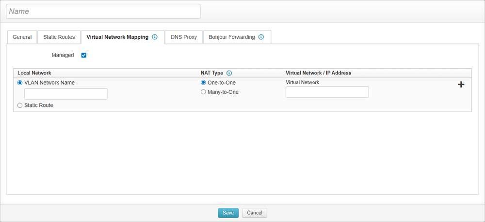
The Virtual Network Mapping tab with Managed selected. Local Network is chosen as either a VLAN or a static route.
A mapping table with three columns:
Column | Choices |
Local Network | VLAN Network Name or Static Route, chosen with a radio pair, then the name or route itself |
NAT Type | One-to-One or Many-to-One |
Virtual Network / IP Address | The virtual network or address the local network is presented as |
NAT Type. One-to-One maps a network onto a network of the same size, so each local address keeps a distinct virtual address. Many-to-One collapses the local network behind a single address.
Static Route as a Local Network depends on the Static Routes tab. With no routes defined, the Local Network selector reports No routes are available. Please define route(s) in the Static Routes tab. Manage and populate the Static Routes tab in the same profile first, then configure the mapping.
DNS Proxy
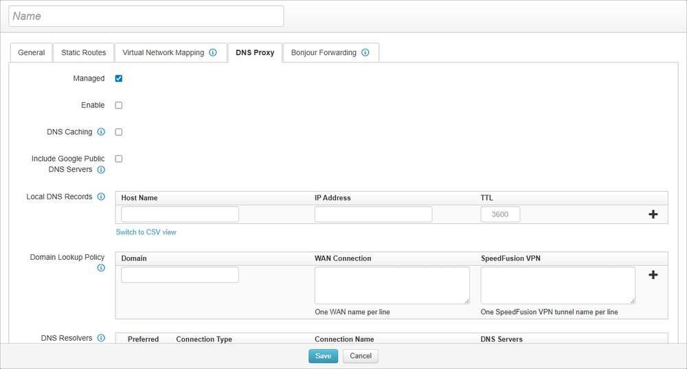
The DNS Proxy tab with Managed selected, showing Local DNS Records, Domain Lookup Policy and DNS Resolvers.
The largest of the four tabs. It starts with three checkboxes:
Control | What it does |
Enable | Turns the DNS proxy on. Separate from Managed, so a managed tab can still be pushed to devices with the DNS proxy switched off |
DNS Caching | Caches lookups on the device |
Include Google Public DNS Servers | Adds Google's public resolvers to the resolver set |
Then three tables:
Section | Columns |
Local DNS Records | Host Name, IP Address, TTL. Carries Switch to CSV view |
Domain Lookup Policy | Domain, WAN Connection, SpeedFusion VPN. The last two are multi line: one WAN name per line, one SpeedFusion VPN tunnel name per line |
DNS Resolvers | Preferred, Connection Type, Connection Name, DNS Servers. Connection Type offers WAN, SpeedFusion Cloud, SpeedFusion VPN, LAN. DNS Servers takes one IP per line |
Note the following:
- Domain Lookup Policy sends lookups for a domain over chosen links. It names the domain, then the WAN connections or SpeedFusion VPN tunnels its lookups should use. Both are typed names and must match the connection names on the device.
- DNS Resolvers has a Preferred flag per row. More than one resolver can be defined. The flag sets which is tried first.
Bonjour Forwarding
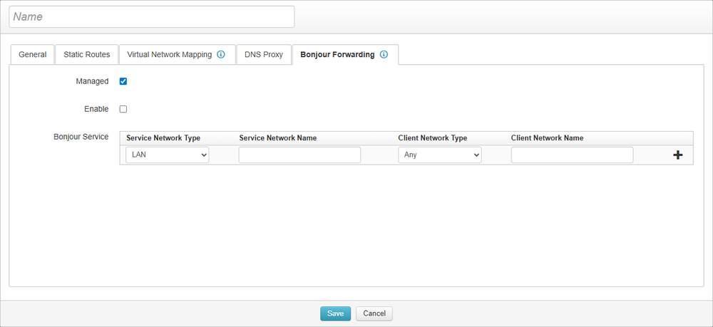
The Bonjour Forwarding tab with Managed selected. Service and client networks are named separately.
An Enable checkbox, then a service table with four columns. Enable is separate from Managed, so a managed tab can still be pushed to devices with Bonjour forwarding turned off.
Column | Choices |
Service Network Type | LAN, SpeedFusion Cloud, SpeedFusion VPN |
Service Network Name | The name of that network |
Client Network Type | Any, LAN, SpeedFusion Cloud, SpeedFusion VPN |
Client Network Name | The name of that network |
The service side and the client side are named separately. The service network is the network of the Bonjour device. The client network is the network of the devices searching for it. Only the client side can be set to Any.
8.10. Route Advertisement
Control which networks the devices in the group advertise over OSPF and RIPv2, so that sites announce a consistent set of routes to their neighbours. A Virtual Network Mapping change requires a matching edit here. The tooltip on that field in LAN Network Settings (8.9 LAN Network Settings) warns that OSPF and RIPv2 settings should be updated as well, to avoid advertising conflicted networks.
Where to find it
Group > Network Settings > Route Advertisement
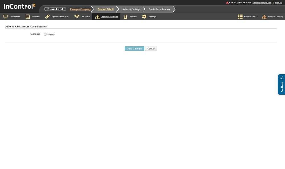
The Route Advertisement screen as it first opens. Everything except the Enable checkbox is hidden until it is selected.
The page is headed OSPF & RIPv2 Route Advertisement.
8.10.1. Switching Group Management On
The screen initially shows Managed and a single Enable checkbox. Selecting Enable shows a full editor with a device selection and four further sections.
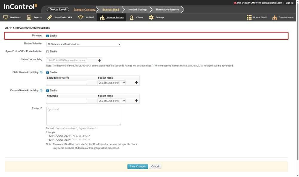
The screen with Enable selected beside Managed, outlined in red. Device Selection and the four advertising sections appear only in this state.
This follows the same pattern as Firewall Rules, Outbound Policy, WAN Configurations and LLDP. The checkbox at the top is a gate, not the setting. Before selecting it, see 8.1.1 Before You Tick a Manage Checkbox.
Clearing Managed returns control to the device. When Managed is cleared and saved, the device's OSPF & RIPv2 Route Advertisement settings return to the values it held before InControl 2 managed them.
8.10.2. Device Selection
Device Selection offers the four choices used elsewhere in this chapter:
- All Balance and MAX devices
- Balance and MAX devices with any of the following tags
- Balance and MAX devices with all of the following tags
- Balance and MAX devices with none of the following tags
8.10.3. The Four Advertising Sections

The four advertising sections with Managed selected. Network Advertising holds one connection name, and the other three Enable checkboxes are cleared.
Section | Controls |
SpeedFusion VPN Route Isolation | An Enable checkbox |
Network Advertising | A text field naming the connections to advertise |
Static Route Advertising | An Enable checkbox, then Excluded Networks taking a network address and a Subnet Mask |
Custom Route Advertising | An Enable checkbox, then Networks taking a network address and a Subnet Mask |
Both Subnet Mask dropdowns hold the full 32 entries, 128.0.0.0 (/1) through 255.255.255.255 (/32).
Note the following:
- Network Advertising names connections. The screen states that the networks of the LAN, VLAN and WAN connections with the specified names will be advertised, and that if no connections' names match, all LAN and VLAN networks will be advertised. Enter connection names exactly as they appear on the device.
- The two route advertising sections take opposite lists. Static Route Advertising takes Excluded Networks, which are not advertised. Custom Route Advertising takes Networks, which are advertised.
The two sections also cover different routes, as the information icon on each states:
Section | What it advertises |
Static Route Advertising | LAN static routes, over OSPF and RIPv2. Static routes that match the Excluded Networks table are not advertised |
Custom Route Advertising | Routes that are not LAN, WAN or Static Routes. Networks added to the Networks table are advertised over OSPF and RIPv2 |
Custom Route Advertising is for routes the other sections do not reach. Its information icon defines its scope as routes that are not LAN, WAN or Static Routes, so a network that already appears in Network Advertising or Static Route Advertising does not need to be added here.
8.10.4. Router ID
A free text area that assigns a router ID per device.
- The format the screen gives is "serial-number","ip-address".
- The example it shows is "1234-AAAA-0001","10.10.10.1" and "1234-BBBB-0002","10.20.20.2".
- The screen states that the router ID will be the router's LAN IP address for devices not specified here. List a device only to assign a different router ID.
- It also states that only serial numbers of devices in this group will be processed. List only devices that belong to the group.
8.10.5. Controls on This Screen
Control | What it does |
Managed | Marks the setting as managed by InControl 2 |
Enable | Reveals the editor and turns OSPF and RIPv2 route advertisement on |
Save Changes | Commits the change. Greyed out until a change is made |
Cancel | Discards the change |
8.11. LLDP
Control whether devices in the group listen for and send LLDP frames, and on which interfaces, LAN or WAN.
Where to find it
Group > Network Settings > LLDP
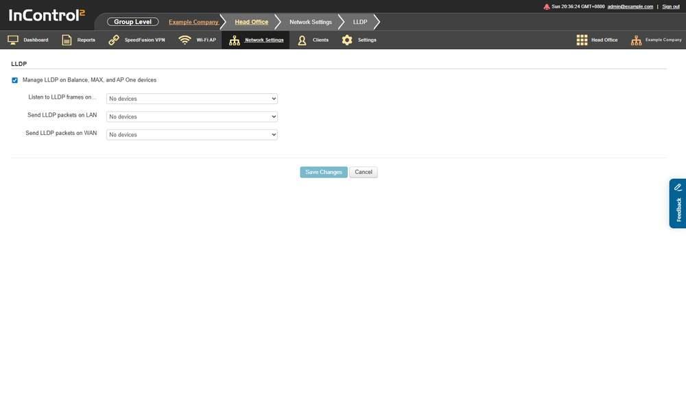
The LLDP screen. Listening and sending are three separate selections, each with its own device scope.
8.11.1. Switching Group Management On
The screen is governed by Manage LLDP on Balance, MAX, and AP One devices. Before selecting it, see 8.1.1 Before You Tick a Manage Checkbox.
8.11.2. Controls on This Screen
Control | What it does |
Manage LLDP on Balance, MAX, and AP One devices | Switches group level LLDP management on or off |
Listen to LLDP frames on… | Selects which devices receive and process LLDP frames |
Send LLDP packets on LAN | Selects which devices advertise LLDP on their LAN interfaces |
Send LLDP packets on WAN | Selects which devices advertise LLDP on their WAN interfaces |
Save Changes | Commits the change. Greyed out until a change is made |
Cancel | Discards the change |
8.11.3. Device Scope
All three selections offer the same five choices:
- No devices
- All devices
- Devices with any of the following tags
- Devices with all of the following tags
- Devices with none of the following tags
Note the following:
- Listening and sending are independent. A device can be set to listen for neighbour advertisements without advertising itself.
- LAN and WAN are separate selections. Sending LLDP on the LAN does not send it on the WAN, and the two can target different sets of devices.
- No devices is a selectable option in its own right, so a selection can be turned off without turning off LLDP management for the whole group.
8.12. IGMP Snooping
Manage IGMP snooping on every Peplink SD Switch in the group from one place, through profiles.
Where to find it
Group > Network Settings > IGMP Snooping
The screen appears in the menu of a group that holds SD Switches.
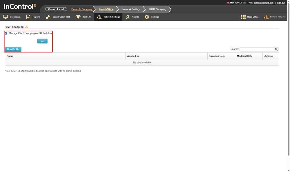
Selecting the Manage checkbox shows Save, New Profile and the profile list. The checkbox, Save and New Profile are outlined in red.

A group already managing IGMP snooping. Its one profile applies to All SD Switches, and the Actions column holds a clone icon and a delete icon.
8.12.1. Switching Group Management On
The screen is governed by Manage IGMP Snooping on SD Switches. Until it is selected, the page shows only that checkbox. Selecting it shows Save, New Profile and the profile list. Click Save to start managing. Before selecting it, see 8.1.1 Before You Tick a Manage Checkbox.
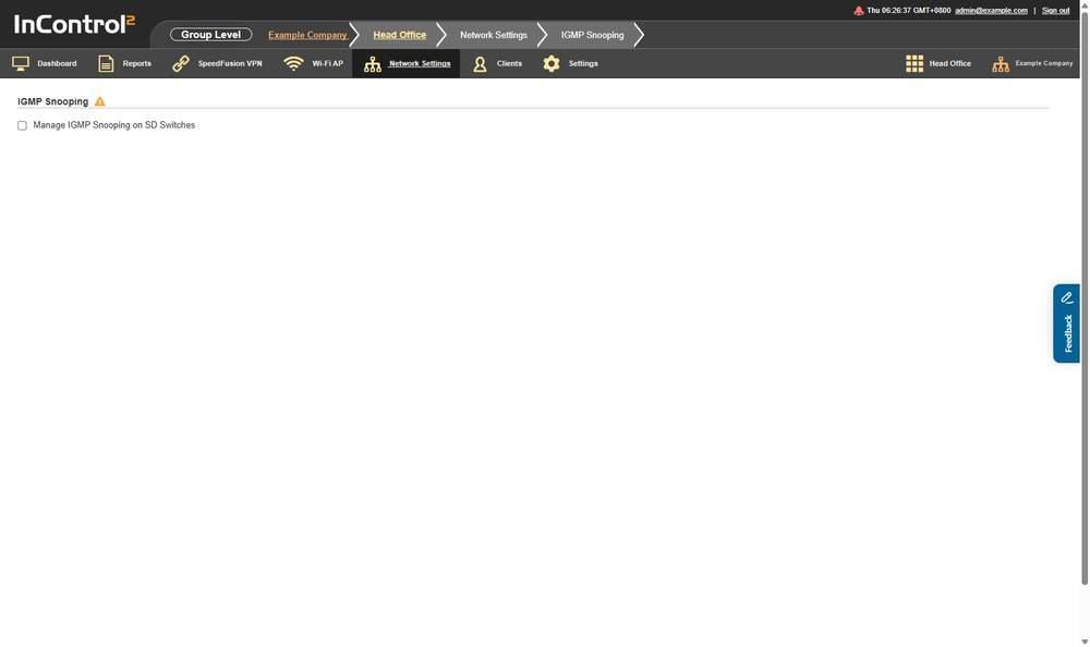
The screen as it first opens. Only the Manage IGMP Snooping on SD Switches checkbox is shown, with a warning icon beside the heading.
A warning icon beside the heading has this tooltip: This setting does not apply to the following SD Switch models: 24 PoE 2.5G Switch, 24 PoE 2.5G Switch Rugged, 48 PoE 2.5G Switch.
8.12.2. The Profile List
Column | What it shows |
Name | The profile name |
Applied on | The switches the profile reaches |
Creation Date | When the profile was created |
Modified Date | When it was last changed |
Actions | Per row actions for that profile |
The page states: Note: IGMP Snooping will be disabled on switches with no profile applied.
Caution: A switch that no profile reaches has IGMP snooping turned off. Check Applied on for every switch before saving.
8.12.3. Creating a Profile
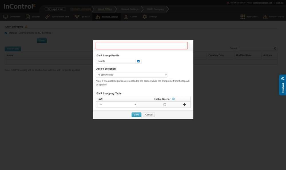
New Profile opens the form. The name box sits at the top, and the IGMP Snooping Table takes one row per LAN.
Field | Notes |
Name | The box at the top of the form |
Enable | Selected by default |
Device Selection | All SD Switches, or SD Switches with any, all or none of the chosen tags |
IGMP Snooping Table | One row per LAN. LAN selects the network, for example Default VLAN, and Enable Querier is a checkbox per row. + adds a row |
The form states: Note: If two enabled profiles are applied to the same switch, the first profile from the top will be applied.
8.13. Port Mirroring
Copy traffic from source ports to a destination port on the group's Peplink SD Switches, through profiles. This supports troubleshooting at remote sites.
Where to find it
Group > Network Settings > Port Mirroring
The screen appears in the menu of a group that holds SD Switches.
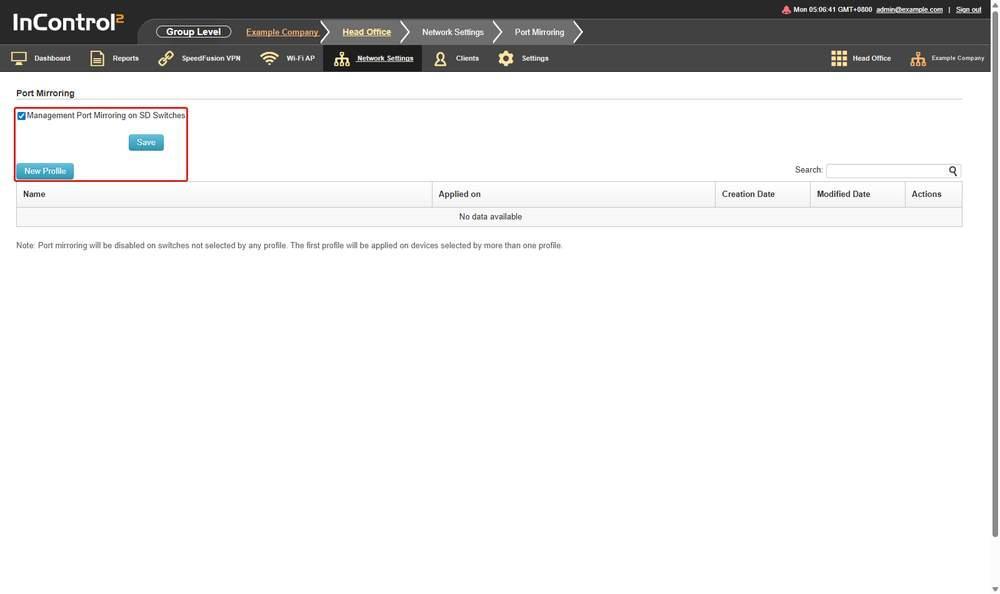
Selecting the Management checkbox shows Save, New Profile and the profile list. The checkbox, Save and New Profile are outlined in red.

A group already managing port mirroring. Its one profile applies to SD Switches carrying a chosen tag, and the note beneath the list states which profile is applied.
8.13.1. Switching Group Management On
The screen is governed by Management Port Mirroring on SD Switches. Until it is selected, the page shows only that checkbox. Selecting it shows Save, New Profile and the profile list. Click Save to start managing. Before selecting it, see 8.1.1 Before You Tick a Manage Checkbox.
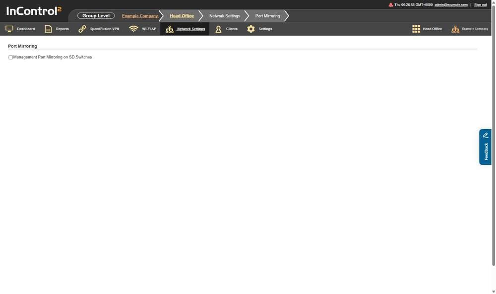
The screen as it first opens. Only the Management Port Mirroring on SD Switches checkbox is shown, cleared.
8.13.2. The Profile List
Column | What it shows |
Name | The profile name |
Applied on | The switches the profile reaches |
Creation Date | When the profile was created |
Modified Date | When it was last changed |
Actions | Per row actions for that profile |
The page states: Note: Port mirroring will be disabled on switches not selected by any profile. The first profile will be applied on devices selected by more than one profile.
8.13.3. Creating a Profile
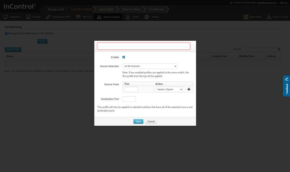
New Profile opens the form. Source Ports takes one row per port, each with its own direction.
Field | Notes |
Name | The box at the top of the form |
Enable | Selected by default |
Device Selection | All SD Switches, or SD Switches with any, all or none of the chosen tags |
Source Ports | One row per port. Port takes the port number and Action offers Ingress / Egress, Ingress or Egress. + adds a row |
Destination Port | The port number that receives the copied traffic |
The form states two notes:
- If two enabled profiles are applied to the same switch, the first profile from the top will be applied.
- This profile will only be applied to selected switches that have all of the selected source and destination ports.
A profile is not applied to a selected switch that lacks one of its ports.
8.14. Captive Portals
Define captive portals for guest sign in, create, reactivate or limit guest accounts, and register the SMS service used by the SMS access mode.
Where to find it
Group > Network Settings > Captive Portals
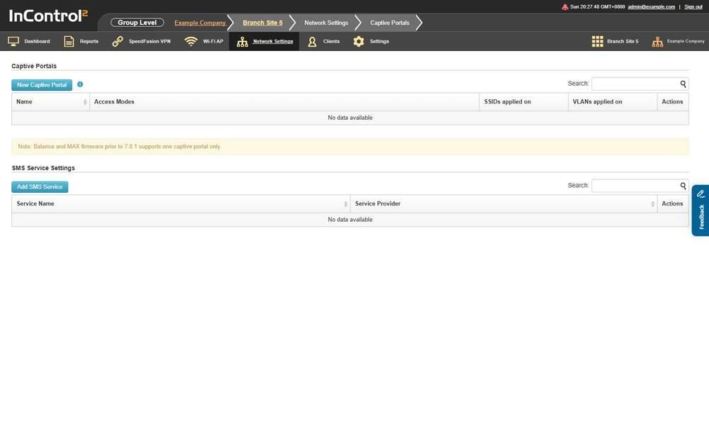
The Captive Portals screen. SMS Service Settings is a second list further down the same page.
The screen has two separate lists, Captive Portals and SMS Service Settings.
8.14.1. The Captive Portal List
Column | What it shows |
Name | The portal name |
Access Modes | The sign-in methods the portal offers |
SSIDs applied on | Which SSIDs the portal is attached to |
VLANs applied on | Which VLANs the portal is attached to |
Actions | Per row actions for that portal |
An empty list shows No data available.
The page shows a firmware note beneath the list: Balance and MAX firmware prior to 7.0.1 supports one captive portal only. Additional portals do not apply to devices on older firmware.
8.14.2. The SMS Service List
Column | What it shows |
Service Name | The name given to the SMS service entry |
Service Provider | The provider the entry uses |
Actions | Per row actions for that entry |
8.14.3. Controls on This Screen
Control | What it does |
New Captive Portal | Opens Captive Portal Settings, for a portal served by InControl 2 |
Add SMS Service | Opens SMS Services |
Search | Filters the list it sits above |
8.14.4. Captive Portal Settings
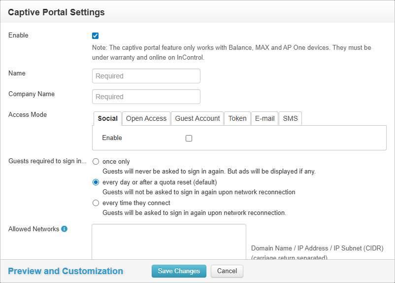
The captive portal editor, with the device and warranty note at the top.
The editor opens with a note stating that the captive portal feature only works with Balance, MAX and AP One devices, and that they must be under warranty and online on InControl 2.
Field | Notes |
Enable | Turns the portal on or off |
Name | The portal name |
Company Name | The company name shown by the portal |
General Description | Free text shown on the portal. Supports markdown syntax for links, in the form the editor gives: This is a hyperlink |
Access Mode | The sign-in methods the portal offers |
Guests required to sign in... | How often a returning guest must sign in again |
Connect to Internet | The text of the button a returning guest sees. See Sign in frequency below |
Allowed Networks | Free text area. Domain Name, IP Address or IP Subnet in CIDR form, one entry per line. Guests can reach these networks before they sign in |
Allowed Clients | Free text area. MAC, IP Address or Host Identifier, one entry per line. These clients go online without signing in at all |
Allowed Grouped MAC Addresses | Selects a MAC address group defined in Grouped MAC Addresses (8.7 Grouped MAC Addresses). Shows None until a group is selected. Define the group there first |
Inactive Timeout | Minutes of inactivity before a client is signed out |
Google Analytics Tracking ID | Adds Google Analytics tracking code to the portal |
Landing Page | Four URL fields for the page a guest is sent to after signing in |
8.14.5. Access Mode
Access Mode offers six methods, each with its own tab in the editor:
Access Mode | Screenshot |
Social |
The Social tab with Enable selected. LinkedIn and Sina Weibo each have a checkbox and an ID field, followed by Time / Data Usage Quota. |
Open Access |
The Open Access tab with Enable selected. Its only setting is Time / Data Usage Quota. |
Guest Account |
The Guest Account tab with Enable selected. Account management is available only after the portal is saved. |
Token |
The Token tab with Enable selected. Token management is available only after the portal is saved. |
The E-mail tab with Enable selected. The four Collect checkboxes and Require Activation are already selected once Enable is selected. Sender E-mail Address receives guest replies. | |
SMS |
The SMS tab in a group with no SMS service. The Enable row holds a message instead of a checkbox. |
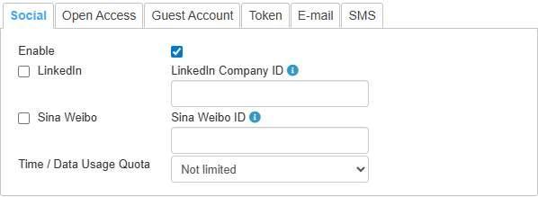

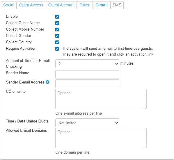

The portal settings below Access Mode are the same on all six tabs. Choosing a different mode changes how a guest signs in, not which portal settings are available.
Social sign in requires a manually obtained ID. The Social tab asks for a page or company ID per network, and the editor explains where to find two of them:
Field | What the editor says |
Sina Weibo | Open a Sina Weibo user page, view its HTML source and search for $CONFIG['oid']=. The ID is shown on the right of the string |
The company ID is the string between /company/ and ? in a LinkedIn Company page URL. In https://www.linkedin.com/company/105127?trk=... the ID is 105127 |
The E-mail mode's Sender E-mail Address receives guest replies. The editor states that if a guest replies to the activation e-mail, the reply goes to this address. Use a monitored mailbox.
SMS has a prerequisite. Until an SMS service exists, the SMS tab shows the message Please close this window and fill in SMS Service Settings first. in place of its Enable control. Add the SMS service before creating the portal.
8.14.6. Guest Account Management
The Guest Account tab creates no accounts of its own. It has a Manage button, which opens a separate screen holding the accounts.
Where to find it
Group > Network Settings > Captive Portals, then the portal's name in the Name column, then the Guest Account tab, then Manage
The account list for one portal. Data Usage Quota reports both the quota and what is left of it, and the name in the Username column opens the account.
The account list belongs to one captive portal, not to the group. Each portal keeps its own accounts, so a group with several portals has several unrelated lists, and an account created under one portal cannot sign in to another. Create the account under the portal the guest connects to.
Column | What it shows |
Username | The name the guest signs in with. Selecting it opens the account |
Data Usage Quota | The account's quota and how much of it remains, for example 100 MB (100 MB left). Unlimited when the account has no quota |
Concurrent Sessions | The session limit set on the account. - when Allow Concurrent Use is off |
Expiry Date | When the account expires, for example Never or 1 day(s) after sign-in, or Expired |
Actions | Present only while Show Expired is on. It holds Reactivate on an expired account and is empty on every other row |
An empty list shows No data available.
Expired accounts are hidden by default. The list opens showing only accounts that are still valid. Click Show Expired to list expired accounts as well.
Control | What it does |
Add User | Opens the account form, described below |
Import | Opens Step 1: CSV File Upload, which creates accounts in bulk from a CSV file |
Update Passwords | Changes the passwords on guest accounts |
Show Expired | Adds expired accounts to the list, greyed out, and adds an Actions column with Reactivate. The button then reads Hide Expired |
Remove User | Deletes the accounts selected in the first column. It is greyed out until a row is selected |
Search | Filters the list by Username |
Download as CSV | Retrieves the list as a CSV file |
Close | Closes the screen and returns to the portal editor |
An expired account is reactivated rather than recreated. Each expired row has a Reactivate button in the Actions column, so an account whose expiry date has passed can be restored instead of being set up again. Rows that have not expired have no button.
A portal's list with Show Expired on. The two expired accounts are greyed out and each offers Reactivate, while the account that is still valid has an empty Actions cell.
8.14.7. The Guest Account Form
Add User and an existing account open the same form.
A new account before anything is enabled. Allow Concurrent Use, Data Usage Quota and Daily Time Quota are checkboxes that show further options when selected.
Field | Notes |
Username | The name the guest signs in with. Required |
Password | The guest's password. Required. Generate fills it in |
Account Expiration | When the account stops working. Four choices, below |
Expire accounts after being inactive for | A separate checkbox, with a number of days. It expires an account that goes unused, independently of the expiry date above |
Allow Concurrent Use | Whether one account may hold more than one session at a time |
Data Usage Quota | A volume cap on the account |
Daily Time Quota | A time cap on the account, in minutes. The form states that it resets at 00:00 midnight |
Account Expiration offers four mutually exclusive settings:
Setting | Notes |
Never | The account does not expire |
N day(s) after the first sign-in | The clock starts when the guest first signs in, not when the account is created |
A fixed date and time | Entered as YYYY-MM-DD HH:MM. Tonight, Tomorrow night and 1 week later fill the field in |
Last day in the month after the first sign-in | Also dated from the first sign in |
The quota controls hide their options until selected. Allow Concurrent Use, Data Usage Quota and Daily Time Quota each show as a checkbox only. Selecting it shows the rest of the setting.
The lower half of the form with all three quota controls enabled. These controls are visible only after scrolling down the form.
Control | What appears once it is selected |
Allow Concurrent Use | Maximum and a list of 2 to 10, or Unlimited, concurrent access session(s) |
Data Usage Quota | A number and a unit of GB or MB, plus the Reset quota every checkbox below it |
Reset quota every | A schedule, plus a time field labelled at. The schedules are N day(s), a chosen weekday of every week, or 1st to 28th or Last day of every month |
Daily Time Quota | A number of minutes |
The form shows a warning when Allow Concurrent Use is selected together with a data quota: when concurrent sessions are enabled, there may be a delay of up to 5 minutes before guest sessions are terminated after the data quota is reached, and actual data usage may significantly exceed the set limit. Where a strict data limit is required, leave Allow Concurrent Use cleared.
The upper half of the form with Allow Concurrent Use and Data Usage Quota selected. The Important note about the data quota appears directly beneath the quota field.
The quota and its reset schedule are set per account. Accounts in the same list can have different quotas, and changing one does not affect the others.
One account's own quota and reset schedule. The account beside it in the same portal is listed as Unlimited.
8.14.8. Importing Guest Accounts
Import replaces the list with a CSV upload step.
The import step. The field description states that three of the five columns are optional and the third is fixed to MB.
The screen states the file's format in full:
Column | What it holds |
1 | Username |
2 | Password |
3 | Data limit by MB, optional. An integer, and the unit is fixed to MB |
4 | Quota Reset Schedule, optional. An integer, or Sunday to Saturday, or 1st to 31st, which is equivalent to choosing the second or third reset schedule on the account form |
5 | Reset time in 24-hour format, optional |
The screen also states:
- Usernames and passwords may contain mixed-case letters, numbers and the symbols found on US keyboards.
- Upper case characters in a username are converted to lower case.
- The minimum length of a username and of a password is 3 characters.
This sample file downloads a template to start from, and the screen recommends editing it in a spreadsheet and saving it back as Comma Separated Values (CSV).
8.14.9. Sign-in Frequency
Guests required to sign in... offers three settings, each with its own explanation in the editor:
Setting | What the editor says |
once only | Guests will never be asked to sign in again. But ads will be displayed if any |
every day or after a quota reset (default) | Guests will not be asked to sign in again upon network reconnection |
every time they connect | Guests will be asked to sign in again upon network reconnection |

The three Guests required to sign in... choices, each with its explanation beneath it. every day or after a quota reset (default) is selected.
every time they connect is what makes the Connect to Internet field visible to guests. That field supplies the button text, and the editor states guests see the button when they reconnect if the portal is configured to require them to sign in every time they connect.
8.14.10. Inactive Timeout
Inactive Timeout applies differently by client type. The editor states that Wi-Fi clients that have disconnected from this SSID for more than this amount of time, or Ethernet clients that have not generated any traffic for more than this amount of time, will be signed out automatically. The editor gives a default of 60 minutes, and suggests 5 minutes when a time-based daily quota is enabled.

Inactive Timeout is entered in minutes, with the editor's explanation and its default beneath the field.
8.14.11. Google Analytics
The editor states the following about the tracking ID field:
- A tracking ID inserts Google Analytics tracking code into the splash page.
- Providing one disables the Cache Splash Page on Devices option below it. Analytics and splash page caching cannot both be used.
- Google Analytics must be configured to match. The editor instructs entering its guest portal address into the Default URL field on the Property Settings screen in Google Analytics. The address differs between organizations, so copy it from the editor.
8.14.12. Landing Page
The Landing Page section sets where a guest goes after signing in. It offers four behaviours, each with its own URL field:
Behaviour | What the editor says |
Signed-in page, then original request | Display a signed-in page with a Start Browsing button. Clicking the button will redirect to the URL the guest user had originally requested. In the auto-login popup browser on iOS and iPadOS, clicking the button will redirect to the URL you supply |
Signed-in page, then fixed URL | Display a signed-in page with a Start Browsing button. Clicking the button will unconditionally redirect to the URL you supply |
Straight to original request | Redirect to the URL the guest user had originally requested. In the auto-login popup browser on iOS and iPadOS, redirect to the URL you supply |
Straight to fixed URL | Redirect to the URL you supply |
The four Landing Page behaviours with their URL fields, and Pass guest's information below them. The note under the heading says the section does not apply to the auto login popup browser on Android.
Note the following:
- The section does not apply to the auto-login popup browser on Android. The editor states that the popup closes immediately after a successful sign in, so an Android guest using it never reaches the landing page.
- iOS and iPadOS have their own destination. Two of the four behaviours have a separate URL for the auto-login popup browser on those platforms, because the original request is not available there.
- Pass guest's information passes the guest's details to the landing page as URL parameters. The editor recommends an HTTPS based URL for security when this is enabled.
8.14.13. Splash Page Caching
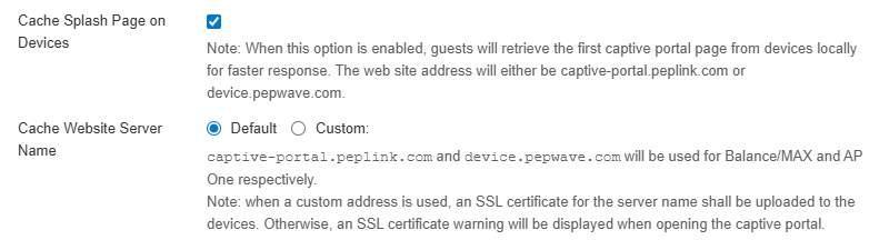
Cache Splash Page on Devices, selected here, with Cache Website Server Name below it set to Default.
Control | What the editor says |
Cache Splash Page on Devices | Guests retrieve the first captive portal page from devices locally for faster response. The web site address will be either captive-portal.peplink.com or device.pepwave.com |
Cache Website Server Name | Default or Custom. Under Default, captive-portal.peplink.com and device.pepwave.com are used for Balance/MAX and AP One respectively |
A custom cache server name needs a certificate. The editor states that when a custom address is used, an SSL certificate for that server name must be uploaded to the devices, otherwise guests see an SSL certificate warning when the captive portal opens.
Caching and Google Analytics are mutually exclusive. Supplying a tracking ID disables Cache Splash Page on Devices (see Google Analytics above).
8.14.14. Other Controls
Control | What it does |
Prevent Immediate Closure of Captive Portal on Android | Delays the closing of the popup browser on Android for a specified number of seconds after a successful sign in |
Guest Session Console | Gives signed in guests a page where they can see and manage their own session. Off by default. Selecting it shows Guest Session Console Website Name |
Preview and Customization | Opens the splash page preview and customisation controls |
Prevent Immediate Closure of Captive Portal on Android is disabled by default. Its tooltip states that the delay lets Android guests see their remaining quota before the popup browser closes, and that it is especially useful for portals with a data usage or time quota enabled. The Landing Page section does not apply to the same Android popup browser.
Guest Session Console takes ports 80 and 443 on the portal's own networks. Its tooltip warns that once the console is enabled, ports 80 and 443 on the LAN and VLAN IP addresses that have the captive portal service enabled can no longer be used to reach the device's web admin. The tooltip suggests moving web admin to different port numbers. Make that change before enabling the console on a device administered over its LAN address.
Selecting the checkbox also does the following:
- It shows Guest Session Console Website Name, an optional field. Guests who type that name into a browser, with or without a scheme, are redirected to the console. The name must contain a dot. Its tooltip also asks for a trusted captive portal SSL certificate for that name, uploaded on the Certificate Management page, otherwise guests see a certificate warning.
- It appends a message to the Additional Message field, as the note beneath the checkbox states.
8.14.15. SMS Services
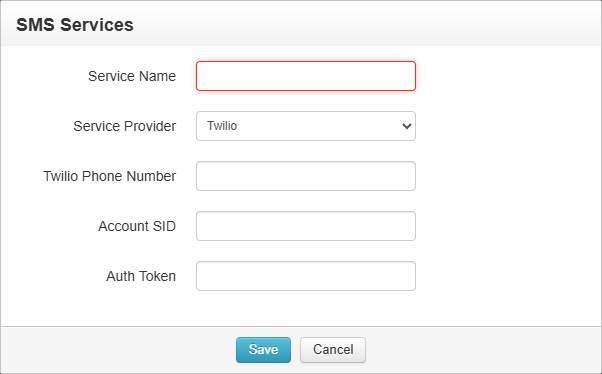
The SMS service editor. The credential fields are Twilio specific.
Field | Notes |
Service Name | The name for this service entry |
Service Provider | The provider. Twilio or Twilio Verify |
Twilio Phone Number | The sending number |
Account SID | The Twilio account identifier |
Auth Token | The Twilio authentication token |
Both providers offered are Twilio products, so an SMS portal depends on a Twilio account.
8.15. Site Survey Schedules
Schedule a scan of the cell towers near qualifying 5G devices, rather than running one on demand.
Where to find it
Group > Network Settings > Site Survey Schedules

The schedule list, empty. Each row is one scheduled scan, and Add creates one.
8.15.1. What This Screen Shows
Each row is one schedule. The grid reads No data available until one is created.
Column | What it shows |
Profile Name | The schedule's name |
Cellular WAN | The cellular WAN the scan runs on |
Schedule | When the scan runs |
Applied on | The devices the schedule is applied to |
Actions | Per schedule actions |
Control | What it does |
Add | Creates a schedule |
Search: | Filters the list |
8.15.2. Which Devices Can Run a Scan
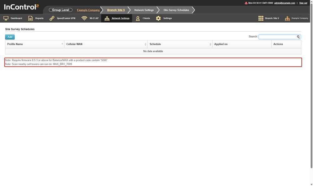
The two notes beneath the schedule list, outlined in red. The second note names the devices in the group that can run a scan.
The screen states the requirements beneath the grid:
Require firmware 8.5.3 or above for Balance/MAX with a product code containing "5GN".
Scan nearby cell towers can run on: followed by the devices in this group that qualify
The second line names the qualifying devices in this group. A device missing from that line does not meet the firmware or product code requirement above.
Scan results are listed per device at Device > Reports > Site Survey, one row per scan, under the name of the profile that produced it. See Device Reports, 15.5 Site Survey.
8.16. Connection Tests
Run the same connectivity test on every selected device on a schedule to detect degraded links, and log the failures. The page states that connection tests require firmware 8.3.0 and 3.9.3 or above for Balance/MAX and AP One respectively. It also states that test profiles reside locally on the device, and that if the device is set to 'status reporting only' for InControl 2, the platform can delete profiles but is restricted from provisioning new ones. Results are shown at Group > Reports > Connection Test Reports (11.10 Connection Test Reports). To e-mail them on a schedule, select a frequency for Connection Test Reports in Group > Settings > Report E-mailing (13.8 Report E-mailing (Group Level)).
Where to find it
Group > Network Settings > Connection Tests
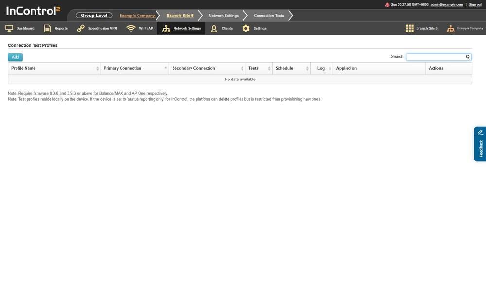
The connection test profile list. Both notes beneath it affect whether a profile reaches a device.
The page is headed Connection Test Profiles.
8.16.1. What This Screen Shows
Column | What it shows |
Profile Name | The profile name |
Primary Connection | The connection the test runs over |
Secondary Connection | The second connection held by the profile, set by the editor's Secondary Connection dropdown. A row reading None tests the primary connection directly, and a row reading OpenVPN tests through an OpenVPN tunnel over it |
Tests | Which tests the profile runs |
Schedule | When the profile runs |
Log | The logging setting for the profile |
Applied on | Which devices the profile targets |
Actions | Per row actions for that profile |
An empty list shows No data available.
8.16.2. Controls on This Screen
Control | What it does |
Add | Opens the connection test profile editor |
Search | Filters the profile list |
8.16.3. Creating a Profile
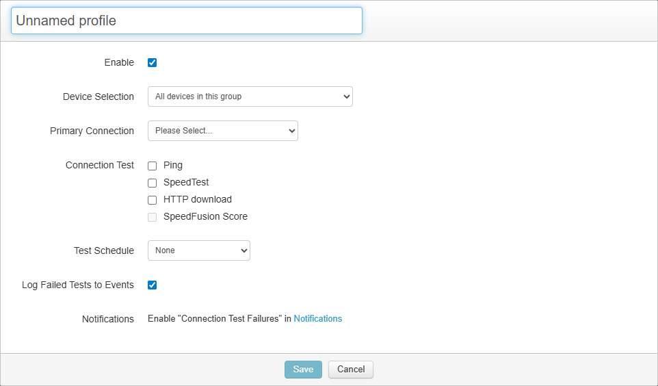
The connection test editor. Logging failures to Events is separate from raising a notification.
Field | Notes |
Name | The profile name |
Enable | Turns the profile on or off without deleting it |
Device Selection | Chooses which devices run the test |
Primary Connection | The connection the test runs over |
Connection Test | Which tests to run |
Schedule | When the test runs |
Log Failed Tests to Events | Writes failures to the event log. Logging and notification are separate. To receive a notification of a failure, enable the notification as well |
Notifications | Points to the Connection Test Fails notification on the Notifications page. See 13.7.5 Events You Can Be Notified About |
Device Selection offers four choices:
- All devices in this group
- Devices with any of the following tags
- Devices with all of the following tags
- Devices with none of the following tags
Primary Connection offers:
- Please Select...
- Ethernet WAN
- Wi-Fi WAN
- Wi-Fi in Air Monitor mode
- Cellular WAN
- Virtual WAN
- SpeedFusion VPN, which needs firmware 8.6.0 or above on the device
- SpeedFusion Connect
Choosing any Primary Connection adds a Connection Name field, which is the name of the connection on the device that the test should run over.
Secondary Connection
Choosing a WAN as the Primary Connection also adds a Secondary Connection dropdown, which is the column of the same name in the profile list. It offers two values:
Value | Effect |
None | The test runs over the primary connection only |
OpenVPN | The test runs through an OpenVPN connection carried over the primary connection |
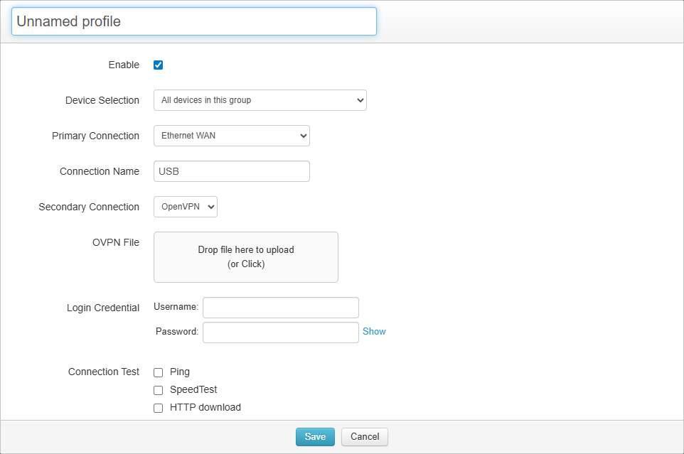
Secondary Connection set to OpenVPN. The OVPN File drop zone and the Login Credential fields appear beneath it.
Selecting OpenVPN adds three things:
Field | Notes |
OVPN File | A drop zone reading Drop file here to upload (or Click). The OpenVPN profile the test should use |
Login Credential: Username | The OpenVPN user name |
Login Credential: Password | The password, with a Show link to reveal what has been typed |
Secondary Connection appears for WAN primaries only. It is offered when Primary Connection is Ethernet WAN, Wi-Fi WAN, Wi-Fi in Air Monitor mode, Cellular WAN or Virtual WAN. It is absent when Primary Connection is SpeedFusion VPN or SpeedFusion Connect, and absent before a Primary Connection is chosen.
Connection Test offers four tests:
- Ping
- SpeedTest
- HTTP download
- SpeedFusion Score Test
All four remain available whichever Primary Connection and Secondary Connection are chosen.
Schedule offers:
- None
- Every Monday, Every Tuesday, Every Wednesday, Every Thursday, Every Friday, Every Saturday, Every Sunday
- Every Day
- Every hour