
9. System Tab
9.1. Admin Security
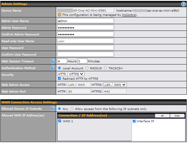
Admin Settings | |||||||||||||||||||||||
Device Name | This field allows you to define a name for this Peplink Balance unit. | ||||||||||||||||||||||
Admin User Name | Admin User Name is set as admin by default, but can be changed. | ||||||||||||||||||||||
Admin Password | This field allows you to specify a new administrator password. | ||||||||||||||||||||||
Confirm Admin Password | This field allows you to confirm the new administrator password. | ||||||||||||||||||||||
Read-only User Name | Read-only User Name is set as user by default, but can be changed, if desired. | ||||||||||||||||||||||
User Password | This field allows you to specify a new user password. Once the user password is set, the read-only user feature will be enabled. | ||||||||||||||||||||||
Confirm User Password | This field allows you to confirm the new user password. | ||||||||||||||||||||||
Web Session Timeout | A web login session will be logged out automatically when it has been idle longer than the Web Session Timeout. Unlimited session timeout: 0 hours 0 minutes. | ||||||||||||||||||||||
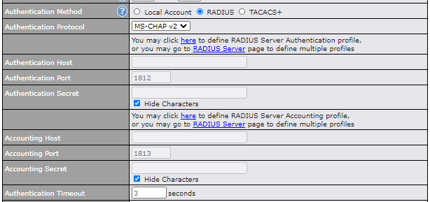
Authentication Method | When External Authentication is selected, the web admin will authenticate using the corresponding external server. Authenticated users are treated as either "admin" with full read-write permission or “user” with read-only access. Local admin and user accounts will be disabled. However, when the device is not able to communicate with the external server, local accounts are enabled to allow emergency access. By default, it is set to Local Account. Available options:
| ||||||||||||||||||||||
Security | This option is for specifying the protocol(s) through which the web admin interface can be accessed:
| ||||||||||||||||||||||
Web Admin Access | This option is for specifying the network interfaces through which the web admin interface can be accessed:
If LAN/WAN is chosen, the WAN Connection Access Settings form will be displayed. | ||||||||||||||||||||||
Web Admin Port | This field is for specifying the port number on which the web admin interface can be accessed. | ||||||||||||||||||||||
Allowed Source IP Subnets | This option is for specifying the IP subnets through which the web admin interface can be accessed.
The allowed IP subnet addresses should be entered into this text area. Each IP subnet must be in the form of w.x.y.z/m, where w.x.y.z is an IP address (e.g. 192.168.0.0), and m is the subnet mask in CIDR format, which is between 0 and 32 inclusively (e.g. 192.168.0.0/24). To define multiple subnets, separate each IP subnet one in a line. For example:
| ||||||||||||||||||||||
Allowed WAN IP Address(es) | This field allows you to select the WAN IP address(es) the web server should connect to. | ||||||||||||||||||||||

9.2. Operating Mode
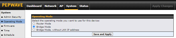
You can select the operating mode you want to use for the access point device. The available options are:
- Router Mode
- Bridge Mode
- Bridge Mode, without LAN IP address
9.3. Firmware
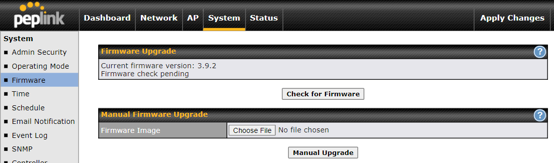
There are two ways to upgrade the unit. The first method is through an online download. The second method is to upload a firmware file manually.
To perform an online download, click on the Check for Firmware button. The access point will check online for new firmware. If new firmware is available, the access point automatically downloads the firmware. The rest of the upgrade process will be automatically initiated.
You may also download a firmware image from the Peplink website and update the unit manually. To update using a firmware image, click Choose File to select the firmware file from the local computer, and then click Manual Upgrade to send the firmware to the access point. It will then automatically initiate the firmware upgrade process.
Please note that all devices can store two different firmware versions in two different partitions. A firmware upgrade will always replace the inactive partition. If you want to keep the inactive firmware, you can simply reboot your device with the inactive firmware and then perform the firmware upgrade.
Firmware Upgrade Status |
Status LED information during firmware upgrade:
|
Important Note |
The firmware upgrade process may not necessarily preserve the previous configuration, and the behavior varies on a case-by-case basis. Consult the release notes for the particular firmware version before installing. Do not disconnect the power during the firmware upgrade process. Do not attempt to upload a non-firmware file or a firmware file that is not supported by Peplink. Upgrading the Peplink Balance with an invalid firmware file will damage the unit and may void the warranty. |
9.4. Time
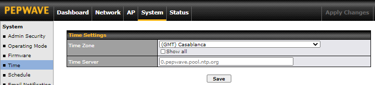
The time server functionality enables the system clock of the access point to be synchronized with a specified time server. The settings for time server configuration are located at System > Time.
Time Settings | |
Time Zone | This specifies the time zone (along with the corresponding Daylight Savings Time scheme) in which Peplink AP operates. The Time Zone value affects the time stamps in the event log of the Peplink AP and e-mail notifications. Check Show all to show all time zone options. |
Time Server | This setting specifies the NTP network time server to be utilized by the Peplink AP. |
9.5. Schedule
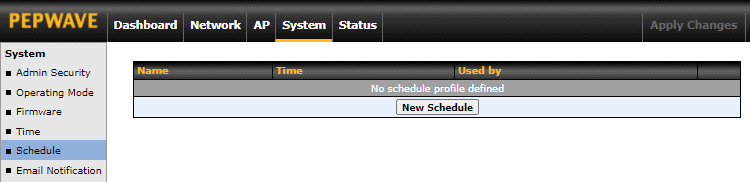
Enable and disable different functions such as WAN connections and SSID at different times, based on a user-scheduled configuration profile. The settings for this are located at System > Schedule.
Click on New Schedule to begin the schedule profile.
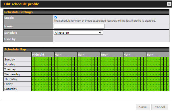
Edit Schedule Profile | |
Enable | Click this checkbox to enable this schedule profile. Note that if this is disabled, then any associated features will also have their scheduling disabled. |
Name | Enter your desired name for this particular schedule profile. |
Schedule | Click the drop-down menu to choose from predefined schedules as your starting point. Please note that upon selecting a predefined schedule, previous changes on the schedule map will be deleted. |
Schedule Map | Click on the desired times to enable features for that time period. You can hold down your mouse button for faster entry. |
9.6. Email Notification
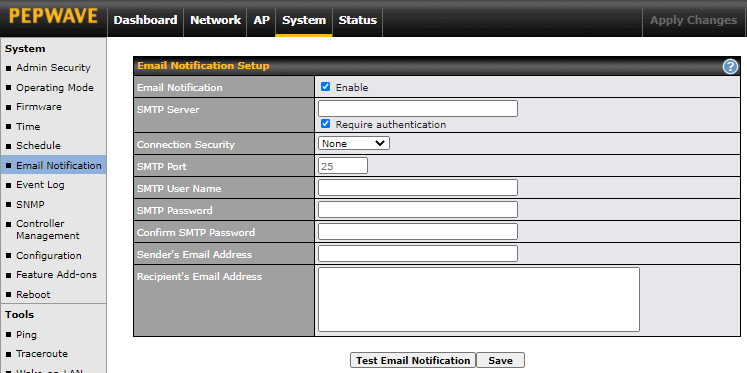
Email notification functionality provides a system administrator with up-to-date information on network status. The settings for configuring email notifications are found at System > Email Notification.
Email Notification Settings | |
Email Notification | This setting specifies whether or not to enable email notification. If Enable is checked, the Peplink AP will send email messages to system administrators when the WAN status changes or when new firmware is available. If Enable is unchecked, email notification is disabled and the Peplink AP will not send email messages. |
SMTP Server | This setting specifies the SMTP server to be used for sending the email notifications. If the server requires authentication, check Require authentication. |
Connection Security | This setting specifies via a drop-down menu one of the following valid connection security options:
When a connection security option is selected, the SMTP Port will automatically set a default port number. |
SMTP Port | This field is for specifying the SMTP port number. By default, this is set to 25. When STARTTLS is selected, the default port number will be set to 587. When SSL/TTS is selected, the default port number will be set to 465. You may customize the port number by editing this field. |
SMTP User Name / Password | This setting specifies the SMTP username and password for accessing the SMTP Server to send the email notifications. These fields are only visible when the Require authentication box is checked in the SMTP Server setting. |
Confirm SMTP Password | This field allows you to verify that the SMTP password matches (if a password is provided in the SMTP Password field). |
Sender’s Email Address | This setting specifies the email address that the Peplink AP will send reports from. |
Recipient's Email Address | This setting specifies the email address(es) to which the Peplink AP will send email notifications. For multiple recipients, separate each email address using the Enter key. |
After you have finished setting up email notifications, you may click the Test Email Notification button to test the settings before saving them. After Test Email Notification is clicked, you will see this screen to confirm the settings:
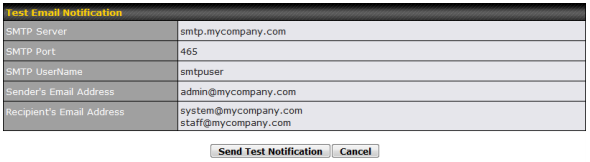
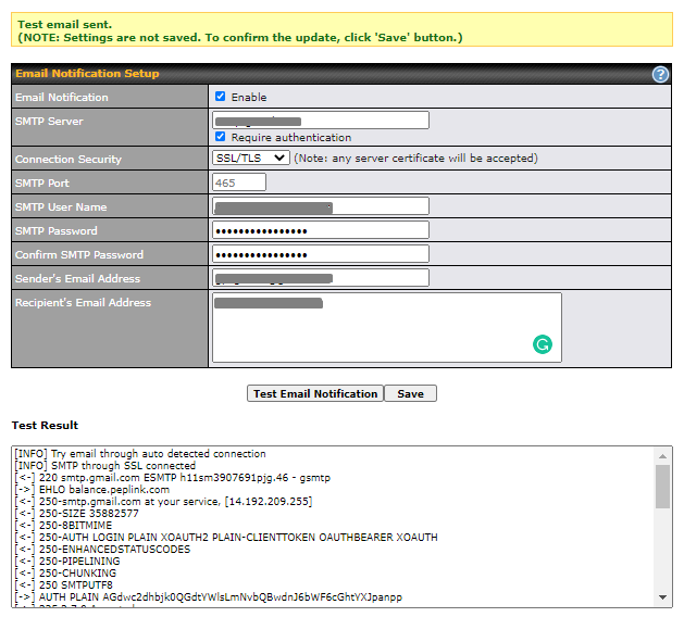
Click Send Test Notification to send the test email with the current settings. In a few seconds, you will see a message with detailed test results.
9.7. Event Log
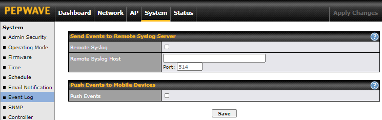
Event log functionality enables event logging at a specified remote syslog server. The settings for configuring the remote system log can be found at System > Event Log.
Remote Syslog Settings | |
Remote Syslog | This setting specifies whether or not to log events at the specified remote syslog server. |
Remote Syslog Host | This setting specifies the IP address or hostname of the remote syslog server. |
Push Event | The Peplink AP can also send push notifications to mobile devices that have our Mobile Router Utility installed. Check the box to activate this feature. For more information on the Router Utility, go to: www.peplink.com/products/router-utility |
9.8. SNMP
SNMP or simple network management protocol is an open standard that can be used to collect information about the Peplink AP unit. SNMP configuration is located at System > SNMP.
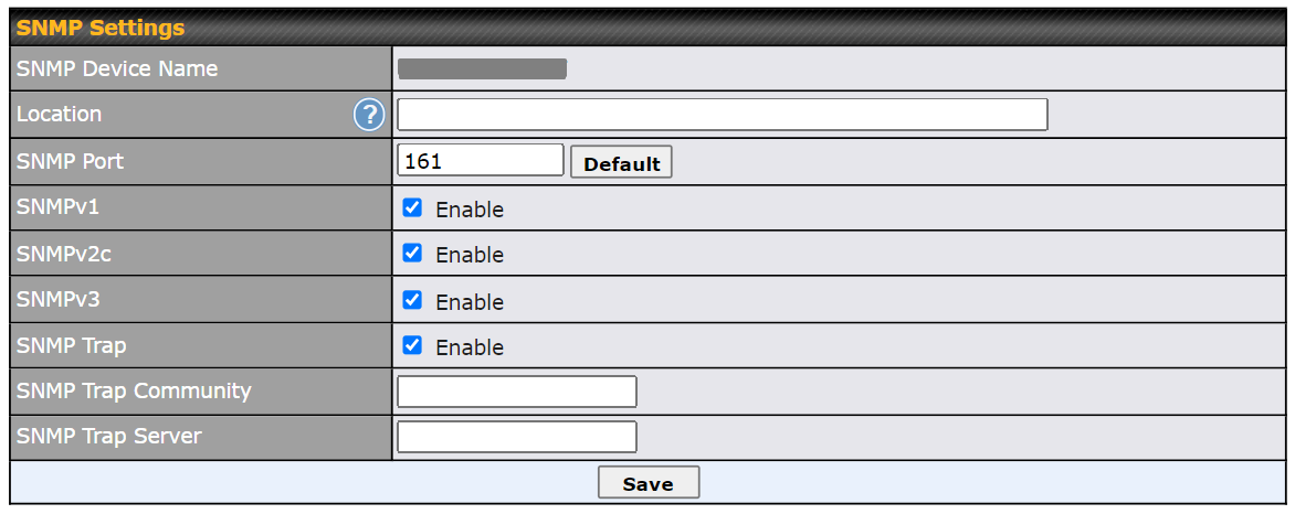
SNMP Settings | |
SNMP Device Name | This field displays the router name defined at System > Admin Security. |
SNMP Port | This option specifies the port which SNMP will use. The default port is 161. |
SNMPv1 | This option allows you to enable SNMP version 1. |
SNMPv2c | This option allows you to enable SNMP version 2c. |
SNMPv3 | This option allows you to enable SNMP version 3. |
SNMP Trap | This option allows you to enable SNMP Trap. If enabled, the following entry fields will appear. |
SNMP Trap Community | This setting specifies the SNMP Trap community name. |
SNMP Trap Server | Enter the IP address of the SNMP Trap server. |
To add a community for either SNMPv1 or SNMPv2c, click the Add SNMP Community button in the Community Name table, upon which the following screen is displayed:
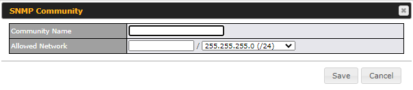
SNMP Community Settings | |
Community Name | This setting specifies the SNMP community name. |
Allowed Network | This setting specifies a subnet from which access to the SNMP server is allowed. Enter the subnet address here (e.g. 192.168.1.0) and select the appropriate subnet mask. |
To define a user name for SNMPv3, click Add SNMP User in the SNMPv3 User Name table, upon which the following screen is displayed:
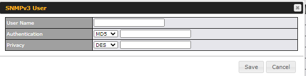
SNMPv3 User Settings | |
User Name | This setting specifies a user name to be used in SNMPv3. |
Authentication Protocol | This setting specifies via a drop-down menu one of the following valid authentication protocols:
When MD5 or SHA is selected, an entry field will appear for the password. |
Privacy | This setting specifies via a drop-down menu one of the following valid privacy protocols:
When DES or AES is selected, an entry field will appear for the password. |
9.9. Controller Management
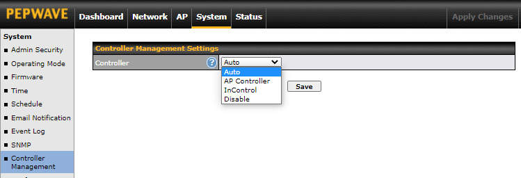
Here is the option to choose the controller management for the access point. This setting specifies via a drop-down menu one of the following valid authentication protocols:
- Auto - AP automatically assigned to active AP Controller.
- AP Controller - AP is controlled by Peplink Balance with AP controller feature.
AP Controller | |
Persistent Controller | Check the box Persistent Controller and enter the IP address of the Peplink Balance under Controller Host. |
- InControl - AP is controlled by InControl*
InControl | |
Restricted to Status Reporting Only | When the box Restricted to Status Reporting Only is ticked, the AP will only report its status, but can’t be managed or configured by InControl. |
Privately Host InControl | Check the box “Privately Host InControl” and enter the IP Address or hostname of your InControl Appliance. |
- Disable - You can disable the controller feature on the AP.
*InControl is a cloud-based service which allows you to manage all of your Peplink devices with one unified system. With it, you can generate reports, gather statistics, and configure your devices automatically.
You can sign up for an InControl account at https://incontrol2.peplink.com. You can register your devices under the account, monitor their status, see their usage reports, and receive offline notifications.
9.10. Configuration
Backing up your Peplink access point settings immediately after successful completion of the initial setup is strongly recommended. The functionality to download and upload Peplink access point settings is found at System > Configuration.
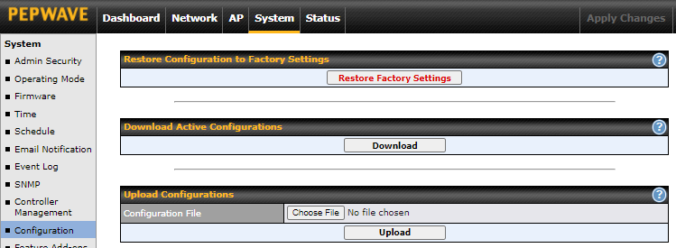
Configuration | |
Restore Configuration to Factory Settings | The Restore Factory Settings button is to reset the configuration to factory default settings. After clicking the button, you will need to click the Apply Changes button on the top right corner to make the settings effective. |
Download Active Configurations | Click Download to back up the current active settings. |
Upload Configurations | To restore or change settings based on a configuration file, click Choose File to locate the configuration file on the local computer, and then click Upload. The new settings can then be applied by clicking the Apply Changes button on the page header, or you can cancel the procedure by pressing discard on the main page of the web admin interface. |
9.11. LED
*Please note that the following settings are available only for AP One AX devices.
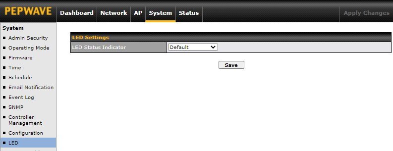
You can control the LED Status Indicator (available only for AP One AX devices). Available options are:
- Default
- Always Turn Off
9.12. Feature Add-Ons
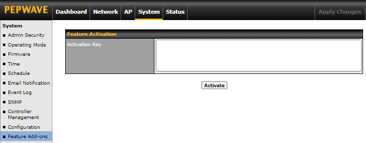
Some Peplink access point models have features that can be activated upon purchase. Once the purchase is complete, you will receive an activation key. Enter the activation key into the Activation Key field, click Activate, and then click Apply Changes.
9.13. Reboot
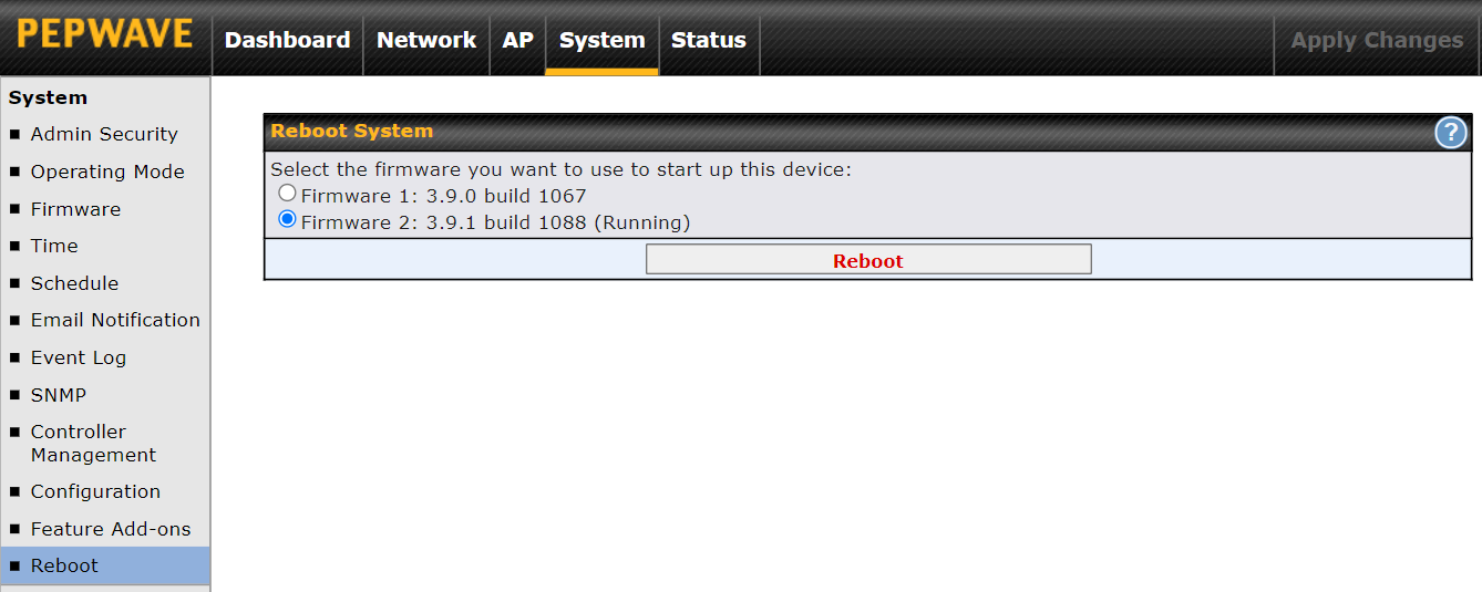
Restart the access point with the Reboot button. For maximum reliability, the Peplink access point can contain two copies of firmware; each copy can be a different version. You can select the firmware version you would like to reboot the device with. The firmware marked with (Running) is the current system boot up firmware.
Please note that a firmware upgrade will always replace the inactive firmware partition.
9.14. Tools
9.14.1. PING
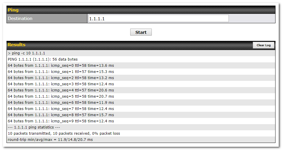
The ping test tool tests connectivity by pinging the specified destination IP address. The ping utility is located at System > Tools > Ping.
9.14.2. Traceroute

The traceroute test tool traces the routing path to the specified IP address. The traceroute test utility is located at System > Tools > Traceroute.
9.14.3. Wake-on-LAN
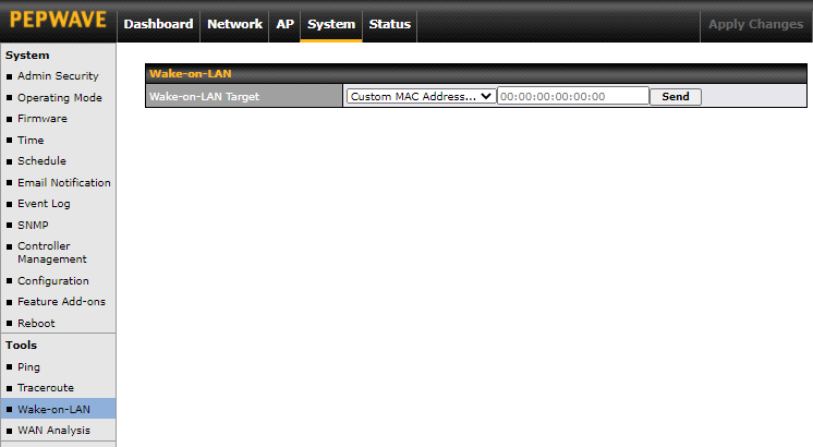
Peplink access points can send Magic Packets to any client specified from the Web UI. To access this feature, navigate to System > Tools > Wake-on-LAN.
Select a client from the drop-down list and click Send to send a Magic Packet.
9.14.4. WAN Analysis
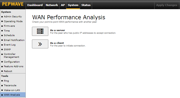
The WAN Analysis feature allows you to run a WAN to WAN speed test between two Peplink devices. You may set up a device as either a server or a client. However, one device must be set up as a server to run the speed tests, and the server must have a public IP address.
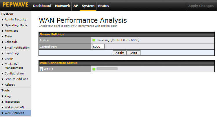
The default Control Port is 6000 and it can be customized if required. The IP address of the WAN interface will be shown in the WAN Connection Status section.
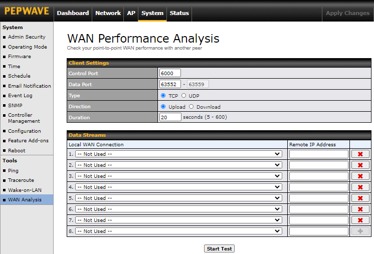
The client side has a few more settings that can be changed. Make sure that the Control Port matches what is entered on the server side. Select the WAN(s) that will be used for testing and enter the server’s WAN IP address(es). Once all of the options have been set, click the Start Test button.
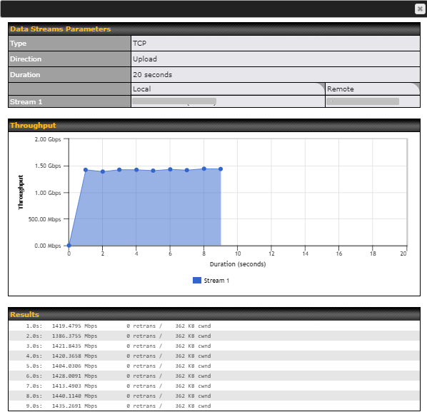
The test output will show the Data Streams Parameters, the Throughput as a graph, and the Results.
The test can be run again once it is complete by clicking the Start button or you can click Close and change the parameters for the test.