7. Network
The settings on the Network tab control WAN, LAN, and Port Settings. It also allows you to set up Captive Portal profiles and Misc Settings.
Additionally, some settings on the Network tab are able to control PepVPN, Inbound Access, NAT Mapping, and QoS when your access point is operating in Router Mode.
7.1. WAN
WAN connection details need to be configured in order to connect the router to the Internet.

To configure a WAN connection, go to Network > WAN from the menu and select the desired WAN connection by clicking on its name.
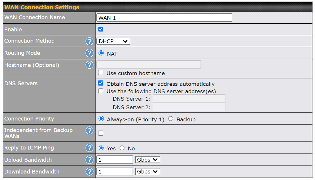
WAN Connection Settings | |
WAN Connection Name | Enter a name to represent this WAN connection. |
Enable | This setting enables the WAN connection. If schedules have been defined, you will be able to select a schedule to apply to the connection. |
Connection Method | There are three possible connection methods for Ethernet WAN:
The connection method and details are determined by, and can be obtained from, the ISP. |
Hostname | Provide a hostname for this WAN port if requested by the ISP. |
DNS Server | Enter the DNS server address that your access point will use to resolve host names. |
Connection Priority | This option allows you to configure the WAN connection, whether for normal daily usage or as a backup connection only. If Always-on is selected, the WAN connection will be kept on continuously, regardless of the priority of other WAN connections. If Backup is selected, the WAN connection will depend on other WAN connections. It will not be used when one or more higher priority dependent WAN connections are connected. |
Independent from Backup WANs | If this is checked, the connection will be working independently from other backup WAN connections. WAN connections whose Connection Priority is set to Backup will ignore the status of this WAN connection, and will be used when none of the other higher priority connections are available. |
Reply to ICMP Ping | If the checkbox is unticked, this option is disabled and the system will not reply to any ICMP ping echo requests to the WAN IP addresses of this WAN connection. Default: ticked (Yes) |
Upload Bandwidth | This field refers to the maximum upload speed. This value is referenced when default weight is chosen for outbound traffic and traffic prioritization. A correct value can result in effective traffic prioritization and efficient use of upstream bandwidth. |
Download Bandwidth | This field refers to the maximum download speed. Default weight control for outbound traffic will be adjusted according to this value. |
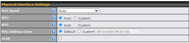
Physical Interface Settings | |
Port Speed | This is the port speed of the WAN connection. It should be set to the same speed as the connected device in case of any port negotiation problems. When a static speed is set, you may choose whether to advertise its speed to the peer device or not. In this setting, Advertise Speed is selected by default. You can choose not to advertise the port speed if the port has difficulty in negotiating with the peer device. The default setting for Port Speed is: Auto. |
MTU | This field is for specifying the Maximum Transmission Unit value of the WAN connection. An excessive MTU value can cause file downloads to stall shortly after connecting. You may consult your ISP for the connection's MTU value. The default value is 1440. |
MSS | This setting should be configured based on the maximum payload size that the local system can handle. The MSS (maximum segment size) is computed from the MTU minus 40 bytes for TCP over IPv4. If the MTU is set to Auto, the MSS will also be set automatically. By default, MSS is set to Auto. |
MAC Address Clone | Some service providers (e.g. cable providers) identify the client’s MAC address and require the client to always use the same MAC address to connect to the network. In such cases, change the WAN interface’s MAC address to the original client PC’s MAC address via this field. The default MAC address is a unique value assigned at the factory. In most cases, the default value is sufficient. Clicking Default restores the MAC address to the default value. |
VLAN | Click the square if you wish to enable VLAN functionality for the WAN connection and enable multiple broadcast domains. Once you enable VLAN, you will be able to enter a name for your network. |
Health Check Settings
To ensure traffic is routed only to healthy WAN connections, the Peplink AP can periodically check the health of each WAN connection. The health check settings for each WAN connection can be independently configured via Network > WAN > *Connection Name* > Health Check Settings.
Health Check Settings | |
Health Check Method | This setting specifies the health check method for the WAN connection. This value can be configured as Disabled, PING, DNS Lookup, or HTTP. The default method is DNS Lookup.
When Disabled is chosen in the method field, the WAN connection will always be considered as up. The connection will NOT be treated as down in the event of IP routing errors.
ICMP ping packets will be issued to test the connectivity with a configurable target IP address or hostname. A WAN connection is considered as up if ping responses are received from either one or both of the ping hosts. PING Host: This setting specifies IP addresses or hostnames with which connectivity is to be tested via ICMP ping. If the Use first two DNS servers as Ping Hosts is checked, the target ping host will be the first DNS server for the corresponding WAN connection. Reliable ping hosts with a high uptime should be considered. By default, the first two DNS servers of the WAN connection are used as the ping hosts.
DNS lookups will be issued to test connectivity with target DNS servers. The connection will be treated as up if DNS responses are received from one or both of the servers, regardless of whether the result was positive or negative. DNS Servers: This field allows you to specify two DNS hosts’ IP addresses with which connectivity is to be tested via DNS Lookup. If the Use first two DNS servers as Health Check DNS Servers is checked, the first two DNS servers will be the DNS lookup targets for checking a connection's health. If the box is not checked, Host 1 must be filled, while a value for Host 2 is optional. If the Include public DNS servers is checked and no response is received from all specified DNS servers, DNS lookups will also be issued to some public DNS servers. A WAN connection will be treated as down only if there is also no response received from the public DNS servers. Connections will be considered as up if DNS responses are received from any one of the health check DNS servers, regardless of a positive or negative result. By default, the first two DNS servers of the WAN connection are used as the health check DNS servers.
HTTP connections will be issued to test connectivity with configurable URLs and strings to match. URL 1: The URL will be retrieved when performing an HTTP health check. When Matching String is left blank, a health check will pass if the HTTP return code is between 200 and 299 (Note: HTTP redirect codes 301 or 302 are treated as failures). When Matching String is filled, a health check will pass if the HTTP return code is between 200 and 299 and if the HTTP response content contains the string. URL 2: If URL 2 is also provided, a health check will pass if either one of the tests passed. |
Timeout | If a health check test cannot be completed within the specified amount of time, the test will be treated as failed. |
Health Check Interval | This is the time interval between each health check test. |
Health Check Retries | This is the number of consecutive health check failures before treating a connection as down. |
Recovery Retries | This is the number of responses required after a health check failure before treating a connection as up again. |




Additional IP Address Settings
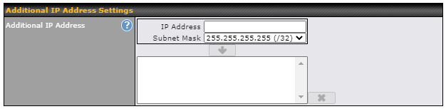
Additional IP Address Settings | |
Additional IP Address | The IP Address list represents the list of fixed Internet IP addresses assigned by the ISP in the event that more than one Internet IP address is assigned to this WAN connection. |
Dynamic DNS Settings
Peplink access points are capable of registering the domain name relationships to dynamic DNS service providers. Through registration with dynamic DNS service provider(s), the default public Internet IP address of each WAN connection can be associated with a host name. With dynamic DNS service enabled for a WAN connection, you can connect to your WAN's IP address from external sources, even if its IP address is dynamic. You must register for an account from the listed dynamic DNS service providers before enabling this option.
If the WAN connection's IP address is a reserved private IP address (i.e. behind a NAT router), the public IP of each WAN will be automatically reported to the DNS service provider.
Either upon a change in IP addresses or every 23 days without link reconnection, the Peplink router will connect to the dynamic DNS service provider to perform an IP address update within the provider’s records.

Dynamic DNS Settings | |
Service Provider | This setting specifies the dynamic DNS service provider to be used for the WAN based on supported dynamic DNS service providers:
When Others… is selected, it supports custom Dynamic DNS servers by entering its URL. Works with any service compatible with DynDNS API. Select Disabled to disable this feature. |
User ID / Username / Email | This setting specifies the registered user name for the dynamic DNS service. |
Password | This setting specifies the password for the dynamic DNS service. |
Hosts | This setting specifies a list of hostnames or domains to be associated with the public Internet IP address of the WAN connection. |
Update All Hosts | Check this box to automatically update all hosts. |
DNS over HTTPS (DoH)
*Please note that the following settings are available only for AP One Rugged (HW2).
You can enable the DoH support in this section.

When this option is enabled, the DNS proxy server will use HTTPS connection to forward DNS requests to the DoH resolver; it will not fall back to traditional UDP DNS.
To configure custom DNS over HTTPS resolver, select Custom URL:, enter resolver URL and IP address.
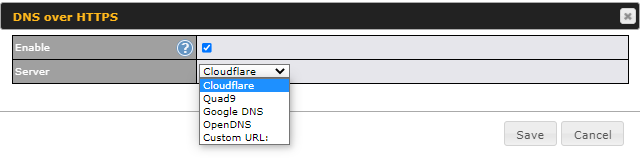
DNS over HTTPS | |
Enable | When this option is enabled, the DNS proxy server will use HTTPS connections to forward DNS requests to the DoH resolver; it will not fall back to traditional UDP DNS options. |
Server | The options to configure DoH with a predefined server are:
|
WAN Quality Monitoring
This setting advises how WAN Quality information is being gathered.

By default, WAN Quality will always be observed and gathered automatically. With customized choice of WAN connections, the device will always observe WAN Quality of those selected WAN connections. Other WAN connections may stop observing WAN Quality information if it is not necessary for the underlying features.
7.2. LAN
7.2.1. Network Settings
LAN interface settings are located at Network > LAN > Network Settings. Navigating to that page will show the following dashboard:

Clicking on any of the existing LAN interfaces (or creating a new VLAN) will show the following:
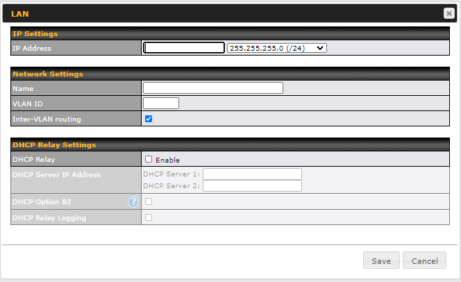
IP Settings | |
IP Address | Enter the LAN IP address and subnet mask of the Peplink access point on the LAN. |
Network Settings | |
Name | Enter a name for the LAN. |
VLAN ID | Enter a number for your VLAN. |
Inter-VLAN routing | Check this box to enable routing between virtual LANs. |
DHCP Relay Settings | |
DHCP Relay | Check the Enable box to enable the DHCP Relay server. |
DHCP Server IP Address | Enter the IP addresses of one or two DHCP servers in the provided fields. The DHCP servers entered here will receive relayed DHCP requests from the LAN. For active-passive DHCP server configurations, enter active and passive DHCP server relay IP addresses in DHCP Server 1 and DHCP Server 2. |
DHCP Option 82 | This feature includes device information as a relay agent for the attached client when forwarding DHCP requests from a DHCP client to a DHCP server. Device MAC address and network name are embedded to circuit ID and Remote ID in option 82. |
DHCP Relay Logging | Enable logging of DHCP events in the eventlog by selecting the checkbox. |
*Please note that the following settings will be available only when your access point is operating in Router Mode.
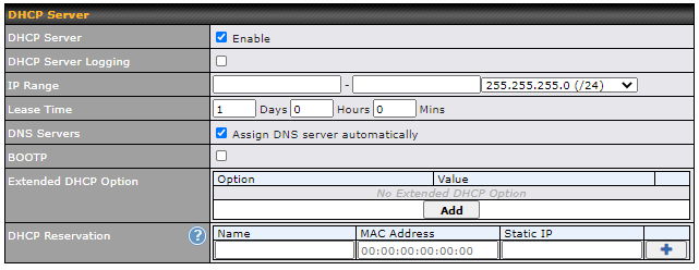
DHCP Server Settings | |
DHCP Server | When this setting is enabled, the DHCP server automatically assigns an IP address to each computer that is connected via LAN and configured to obtain an IP address via DHCP. The Peplink router’s DHCP server can prevent IP address collision on the LAN. |
DHCP Server Logging | Enable logging of DHCP events in the eventlog by selecting the checkbox. |
IP Range | These settings allocate a range of IP addresses that will be assigned to LAN computers by the Peplink router’s DHCP server. |
Lease Time | This setting specifies the length of time throughout which an IP address of a DHCP client remains valid. Upon expiration of the lease time, the assigned IP address will no longer be valid and renewal of the IP address assignment will be required. |
DNS Servers | This option allows you to input the DNS server addresses to be offered to DHCP clients. If Assign DNS server automatically is selected, the Peplink router’s built-in DNS server address (i.e. LAN IP address) will be offered. |
BOOTP | Check this box to enable BOOTP on older networks that still require it. |
Extended DHCP Option | In addition to standard DHCP options (e.g., DNS server address, gateway address, subnet mask), you can specify the value of additional extended DHCP options, as defined in RFC 2132. With these extended options enabled, you can pass additional configuration information to LAN hosts. To define an extended DHCP option, click the Add button, choose the option to define, and then enter its value. For values that are in IP address list format, you can enter one IP address per line in the provided text area input control. Each option can be defined once only. |
DHCP Reservation | This setting reserves the assignment of fixed IP addresses for a list of computers on the LAN. The computers to be assigned fixed IP addresses on the LAN are identified by their MAC addresses. The fixed IP address assignment is displayed as a cross-reference list between the computers’ names, MAC addresses, and fixed IP addresses. Name (an optional field) allows you to specify a name to represent the device. MAC addresses should be in the format of 00:AA:BB:CC:DD:EE. Click on |
 to create a new record. Click on
 to remove a record. Reserved clients information can be imported from the Client List, located at Status > Client List.
7.2.2. Port Settings
To configure port settings, navigate to Network > LAN > Port Settings.

On this screen, you can configure the name of the LAN port and enable or disable a specific port.
7.3. PepVPN
PepVPN securely connects one or more remote sites to the site running your access point.
*Please note that the following settings will be available only when your access point is operating in Router Mode.
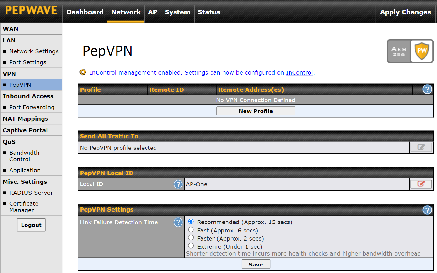
To set up PepVPN, first give your site a local PepVPN ID. To modify an existing local ID,
click on  .

Once you’ve specified a local ID, click the New Profile button to configure PepVPN.

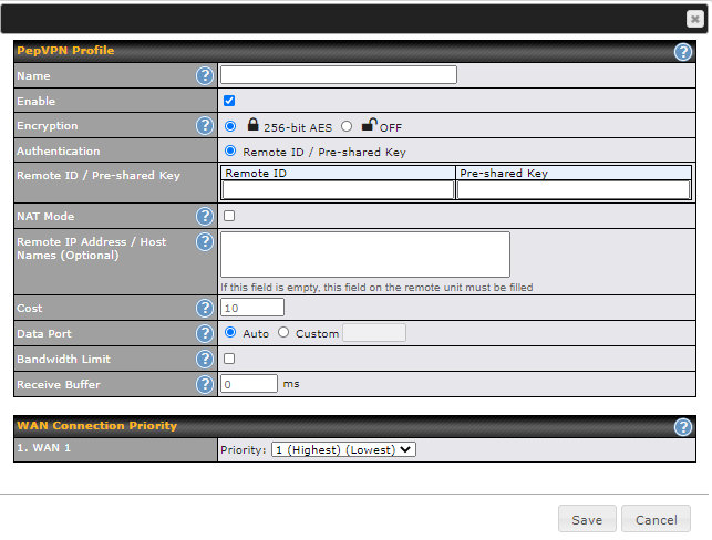
PepVPN Profile Settings | |
Name | Enter a name to represent this profile. The name can be any combination of alphanumeric characters (0-9, A-Z, a-z), underscores (_), dashes (-), and/or non-leading/trailing spaces ( ). |
Enable | Check this box to enable PepVPN. |
Encryption | By default, VPN traffic is encrypted with 256-bit AES. If Off is selected on both ends of a VPN connection, no encryption will be applied. |
Authentication | Select Remote ID / Pre-shared Key to specify the method your access point will use to authenticate peers. When selecting Remote ID / Pre-shared Key, be sure to enter a unique peer ID number in the Remote ID field. |
Remote ID / Pre-shared Key | This optional field becomes available when Remote ID / Pre-shared Key is selected as the Peplink access point’s VPN Authentication method, as explained above. Pre-shared Key defines the pre-shared key used for this particular VPN connection. The VPN connection's session key will be further protected by the pre-shared key. The connection will be up only if the pre-shared keys on each end match. |
NAT Mode | Check this box to allow the local DHCP server to assign an IP address to the remote peer. When NAT Mode is enabled, all remote traffic over the VPN will be tagged with the assigned IP address using network address translation. |
Remote IP Address / Host Names (Optional) | If NAT Mode is not enabled, you can enter a remote peer’s WAN IP address or hostname(s) here. If the remote peer uses more than one address, enter only one of them here. Multiple hostnames are allowed and can be separated by a space character or carriage return. Dynamic-DNS host names are also accepted. This field is optional. With this field filled, the Peplink Balance will initiate connection to each of the remote IP addresses until it succeeds in making a connection. If the field is empty, the Peplink Balance will wait for connection from the remote peer. Therefore, at least one of the two VPN peers must specify this value. Otherwise, VPN connections cannot be established. |
Cost | Define path cost for this profile. OSPF will determine the best route through the network using the assigned cost. Default: 10 |
Data Port | This field specifies the outgoing UDP port number for transporting VPN data. If Default is selected, port 4500 will be used by default. Port 32015 will be used if port 4500 is unavailable. If Custom is selected, you can input a custom outgoing port number between 1 and 65535. |
Bandwidth Limit | Define maximum download and upload speed to each individual peer. This functionality requires the peer to use PepVPN version 4.0.0 or above. |
Receive Buffer | Receive Buffer can help to reduce out-of-order packets and jitter, but will introduce extra latency to the tunnel. Default is 0 ms, which disables the buffer, and the maximum buffer size is 2000 ms. |
WAN Connection Priority | |
WAN Connection Priority | If your device supports it, you can specify the priority of WAN connections to be used for making VPN connections. WAN connections set to OFF will never be used. Only available WAN connections with the highest priority will be used. To enable asymmetric connections, connection mapping to remote WANs, cut-off latency, and packet loss suspension time, click the |
 button.

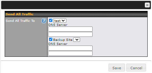
Send All Traffic To | |
This feature allows you to redirect all traffic to a specified PepVPN connection. Click the
You could also specify a DNS server to resolve incoming DNS requests. Check the box next to Backup Site to designate a backup SpeedFusion profile that will take over should the main PepVPN connection fail. |
 button to select your connection and the following menu will appear:

Link Failure Detection Time | |
Link Failure Detection Time | The bonded VPN can detect routing failures on the path between two sites over each WAN connection. Failed WAN connections will not be used to route VPN traffic. Health check packets are sent to the remote unit to detect any failure. The more frequently checks are sent, the shorter the detection time, although more bandwidth will be consumed. When Recommended (default) is selected, a health check packet is sent every five seconds, and the expected detection time is 15 seconds. When Fast is selected, a health check packet is sent every three seconds, and the expected detection time is six seconds. When Faster is selected, a health check packet is sent every second, and the expected detection time is two seconds. When Extreme is selected, a health check packet is sent every 0.1 second, and the expected detection time is less than one second. |
7.4. Inbound Access
*Please note that the following settings will be available only when your access point is operating in Router Mode.
7.4.1. Port Forwarding
Peplink access points can act as a firewall that blocks, by default, all inbound access from the Internet. Inbound port forwarding rules can be defined at Network > Inbound Access > Port Forwarding.
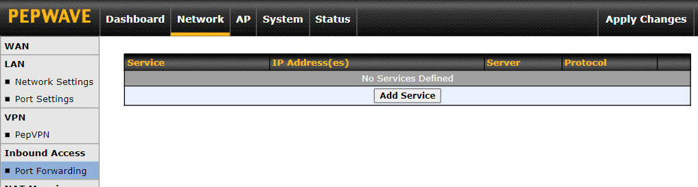
To define a new service, click Add Service.
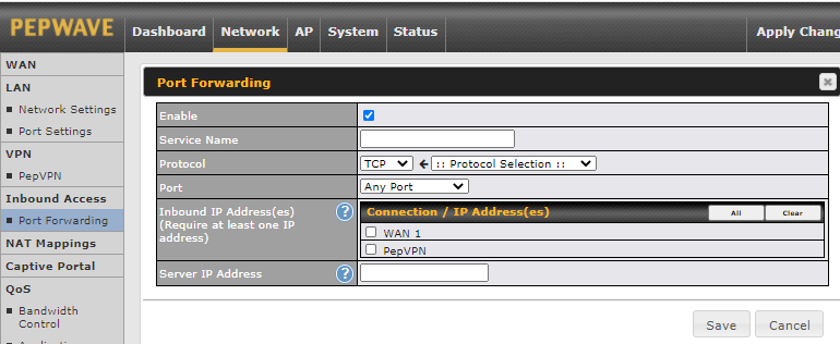
Port Forwarding Settings | |
Enable | Check the box to enable the port forwarding profile for Inbound Access. |
Service Name | This setting identifies the service to the system administrator. Valid values for this setting consist of only alphanumeric and underscore “_” characters. |
Protocol | The Protocol setting, along with the Port setting, specifies the protocol of the service as TCP, UDP, ICMP, or IP. Traffic that is received by the Peplink access point via the specified protocol at the specified port(s) is forwarded to the LAN hosts specified by the server setting. Please see below for details on the Port and server settings. Alternatively, the Protocol Selection Tool drop-down menu can be used to automatically fill in the protocol and a single port number of common Internet services (e.g., HTTP, HTTPS, etc.). After selecting an item from the Protocol Selection Tool drop-down menu, the protocol and port number remain manually modifiable. |
Port | The Port setting specifies the port(s) that correspond to the service, and can be configured to behave in one of the following manners:
Any Port: all traffic that is received by the Peplink router via the specified protocol is forwarded to the server specified by the server setting. For example, with IP Protocol set to TCP, and Port set to Any Port, all TCP traffic is forwarded to the configured servers.
Single Port: traffic that is received by the Peplink router via the specified protocol at the specified port is forwarded via the same port to the server specified by the server setting. For example, with IP Protocol set to TCP, Port set to Single Port, and the port set to 80, TCP traffic received on port 80 is forwarded to the configured servers via port 80.
Port Range: traffic that is received by the Peplink router via the specified protocol at the specified port range is forwarded via the same respective ports to the LAN hosts specified by the server setting. For example, with IP Protocol set to TCP, Port set to Port Range, and the port range set to 80-88, TCP traffic received on ports 80 through 88 is forwarded to the configured servers via the respective ports.
Port Mapping: traffic that is received by the Peplink router via the specified protocol at the specified port is forwarded via a different port to the servers specified by the server setting. For example, with the IP Protocol set to TCP, the Port set to Port Mapping, the port set to 80, and the Map to Port set to 88, TCP traffic on port 80 is forwarded to the configured servers via port 88.
Range Mapping: traffic that is received by the Peplink router via the specified protocol at the specified port range is forwarded via a different port to the servers specified by the server setting. |
Inbound IP Address(es) | This setting specifies the WAN connections and Internet IP address(es) from which the service can be accessed. |
Server IP Address | This setting specifies the LAN IP address of the server that handles the requests for the service. |





7.5. NAT Mapping
NAT mappings allow IP address mapping of all inbound and outbound NAT’d traffic to and from an internal client IP address. Settings to configure NAT mappings are located at Network > NAT Mappings.
*Please note that the following settings will be available only when your access point is operating in Router Mode.
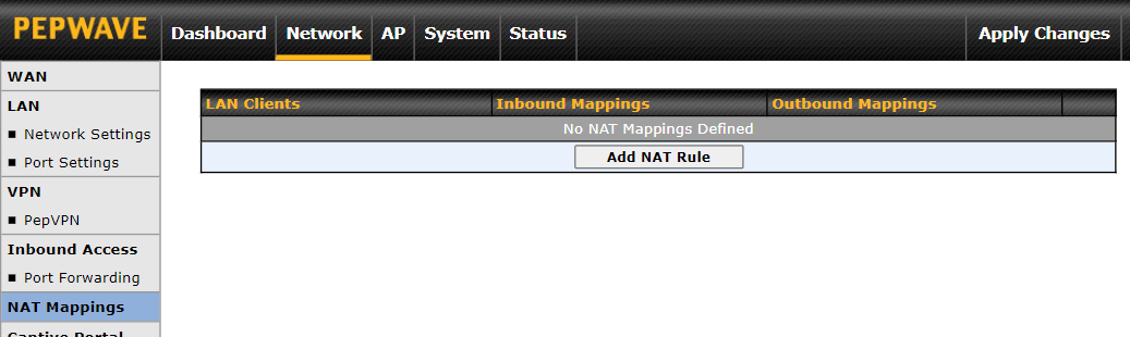
To add a rule for NAT mappings, click Add NAT Rule.
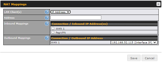
NAT Mapping Settings | |
LAN Client(s) | NAT mapping rules can be defined for a single LAN IP Address, an IP Range, or an IP Network. |
Address | This is the IP address of the LAN host where the system will map the selected connection IP addresses. |
Inbound Mappings | This section is to define which inbound IP addresses should be forwarded to the LAN Client(s). |
Outbound Mappings | This section is to define which IP addresses of each WAN should be used when an IP connection is made from the LAN host to the Internet. |
7.6. Captive Portal
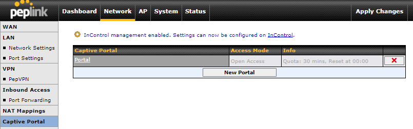
The captive portal serves as a gateway that clients have to pass if they wish to access the Internet using your router. To configure the captive portal, navigate to Network > Captive Portal.
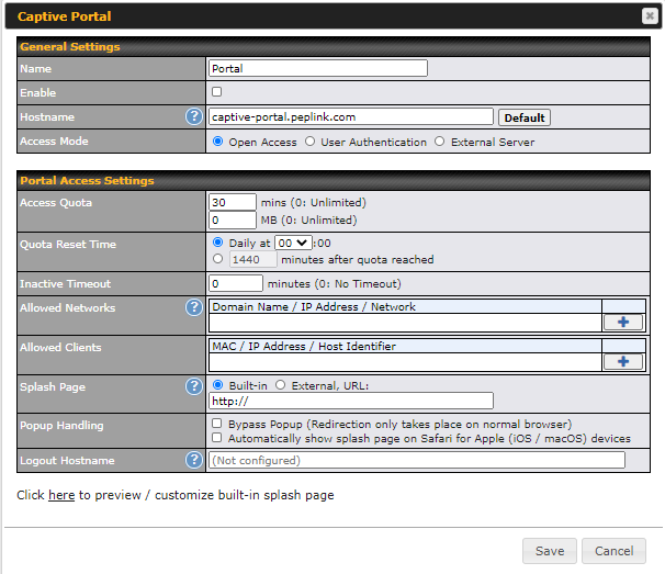
Captive Portal Settings | |
Name | Enter a name for the Captive Portal Profile. |
Enable | Check the Enable box to turn on your access point’s built-in captive portal functionality. |
Hostname | To customize the portal’s form submission and redirection URL, enter a new URL in this field. |
Access Mode | Open Access allows clients to freely access your router. User Authentication forces your clients to authenticate before accessing your router. External Server uses the captive portal with HotSpotSystem or CoovaChilli. As described in the following knowledgebase article: https://forum.peplink.com/t/using-hotspotsystem-wi-fi-on-Peplink-max-routers/ |
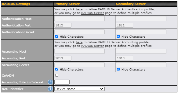
User Authentication | This authenticates your clients through a RADIUS server. After selecting this option, you will see the following fields:
Fill in the necessary information to complete your connection to the server and enable authentication. |
Access Quota | Enter a value in minutes to limit access time on a given login or enter 0 to allow unlimited use time on a single login. Likewise, enter a value in MB for the total bandwidth allowed or enter 0 to allow unlimited bandwidth on a single login. |
Quota Reset Time | This menu determines how your usage quota resets. Setting it to Daily will reset it at a specified time every day. Setting a number of minutes after quota reached establishes a timer for each user that begins after the quota has been reached. |
Inactive Timeout | Enter a value in minutes to log out following the specified period of inactivity or enter 0 to disable inactivity logouts. |
Allowed Networks | To whitelist a network, enter the domain name / IP address here and click the |
Allowed Clients | To whitelist a client, enter the MAC address / IP address here and click the To delete an existing client from the list of allowed clients, click the |
Splash Page | Here, you can choose between using the Peplink access point’s built-in captive portal or redirecting clients to a URL that you define. |
Popup Handling | Configurable options for popup handling:
|
Logout Hostname | A hostname that can be used to logout captive portal when being accessed on the browser. |
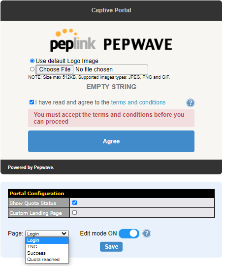
Customize splash page | Click on the provided link in the Captive Portal Profile to customize the splash page. A new browser tab with a WYSIWYG editor of the splash page will be opened. To edit the content, switch Edit Mode on and select the corresponding elements to edit. |
 . To delete an existing network from the list of allowed networks, click the
 button next to the listing.
 .
 button next to the listing.
7.7. QoS
*Please note that the following settings will be available only when your access point is operating in Router Mode.
7.7.1. User Group
*Please note that the following settings are available only for AP One Rugged (HW2).
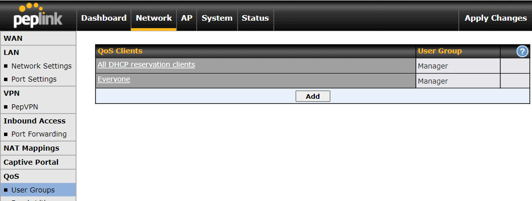
LAN and PPTP clients can be categorized into three user groups - Manager, Staff, and Guest. This table allows you to define rules and assign client IP addresses or subnets to a user group. You can apply different bandwidth and traffic prioritization policies on each user group in the Bandwidth Control and Application sections.
The table is automatically sorted, and the table order signifies the rules' precedence. The smaller and more specific subnets are put towards the top of the table and have higher precedence; larger and less specific subnets are placed towards the bottom.
Click the Add button to define clients and their user group. Click the  button to remove the defined rule.
Two default rules are pre-defined and put at the bottommost. They are All DHCP reservation clients and Everyone, and they cannot be removed. All DHCP reservation clients represents the LAN clients defined in the DHCP Reservation table in the LAN settings page. Everyone represents all clients that are not defined in any rule above. Click on a rule to change its group.
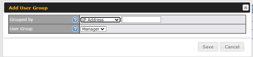
Add / Edit User Group | |
Subnet / IP Address | From the drop-down menu, choose whether you are going to define the client(s) by an IP Address or a Subnet. |
User Group | This field is to define which User Group the specified subnet / IP address belongs to. |
Once users have been assigned to a user group, their internet traffic will be restricted by rules defined for that particular group. Please refer to the following two sections for details.
7.7.2. Bandwidth Control
7.7.2.1 Group Bandwidth Reservation
*Please note that the following settings are available only for AP One Rugged (HW2).
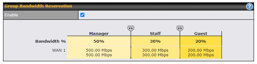
This section is to define how much minimum bandwidth will be reserved to each user group when a WAN connection is in full load. When this feature is enabled, a slider with two indicators will be shown. You can move the indicators to adjust each group's weighting. The lower part of the table shows the corresponding reserved download and upload bandwidth value of each connection.
By default, 50% of bandwidth has been reserved for Manager, 30% for Staff, and 20% for Guest.
7.7.2.2 Individual Bandwidth Limit
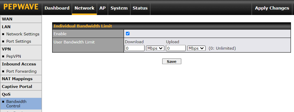
The default download and upload limits are set to unlimited (set as 0). This can be changed as necessary to restrict the speeds to individual devices connected to the router, no matter if they are wired or wireless. Note that this limit is applied to all connected devices.
7.7.3. Application
You can choose whether to apply the same prioritization settings to all user groups or customize the settings for each group.
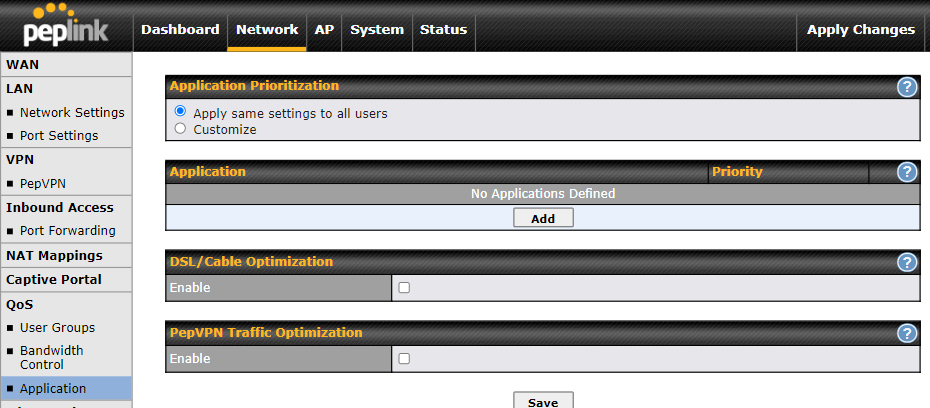
Define the priority level of selected applications. Available priorities are ↑High,━ Normal, and ↓Low. Applications not defined in the table are assigned a "Normal" priority level.
Peplink access points can detect various application traffic by inspecting the packets' content. Select an application by choosing a supported application, or by manually defining a custom application. The priority preference of supported applications is placed at the top of the table. Custom applications are at the bottom.

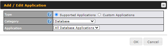
Click the Add button to define a custom application. Click the  button in the Action column to delete the custom application in the corresponding row.

When Supported Applications is selected, the Peplink access point will inspect network traffic and prioritize the selected applications. Alternatively, you can select Custom Applications and define the application by providing the protocol, scope, port number, and DSCP value.
DSL / Cable Optimization

DSL/cable-based WAN connections normally have their upload bandwidth set lower than their download bandwidth. When a DSL/cable circuit's uplink is congested, the download bandwidth will be affected. Users will not be able to download data at full speed until the uplink becomes less congested. The DSL/Cable Optimization can relieve such issues. When it is enabled, the download speed will be less affected by the upload traffic.
PepVPN Traffic Optimization

Check the box to enable PepVPN traffic to have the highest priority when the WAN is congested.
7.8. Misc. Settings
7.8.1. Radius Server
RADIUS Server settings are located at Network > Misc. Settings > RADIUS Server.
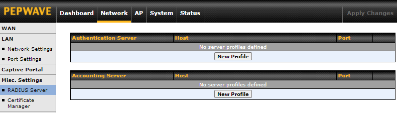
Click New Profile to display the following screen:
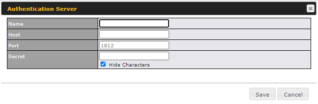
Authentication Server | |
Name | This field is for specifying a name to represent this profile. |
Host | Specifies the IP address or hostname of the RADIUS server host. |
Port | This setting specifies the UDP destination port for authentication requests. By default, the port number is 1812. |
Secret | This field is for entering the secret key for communicating to the RADIUS server. |
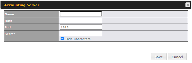
Accounting Server | |
Name | This field is for specifying a name to represent this profile. |
Host | Specifies the IP address or hostname of the RADIUS server host. |
Port | This setting specifies the UDP destination port for authentication requests. By default, the port number is 1813. |
Secret | This field is for entering the secret key for communicating to the RADIUS server. |
7.8.2. Certificate Manager
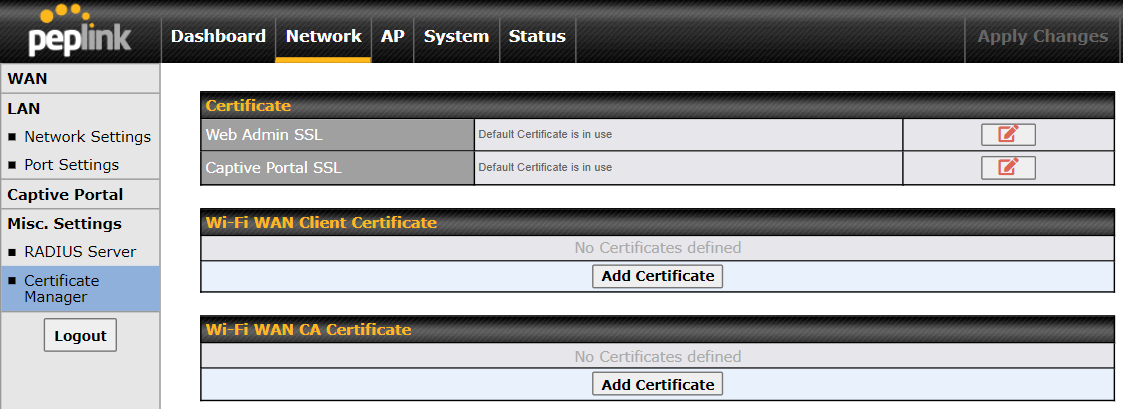
This section allows for certificates to be assigned to the Web Admin SSL, Captive Portal SSL and Wi-Fi WAN (Client and CA).
The following knowledge base article describes how to create self-signed certificates and import them to a Peplink Product.
7.8.3. GPIO
The GPIO and Ignition sensing features are supported by AP One Rugged (HW2).
GPIO (General Purpose Input/Output) and Ignition Sensing are specifically designed for vehicular, IoT, and industrial deployments. For more information, kindly refer to the link below:
https://download.peplink.com/resources/gpio_and_ignition_sensing_guide.pdf
7.9. Ignition Sensing Installation
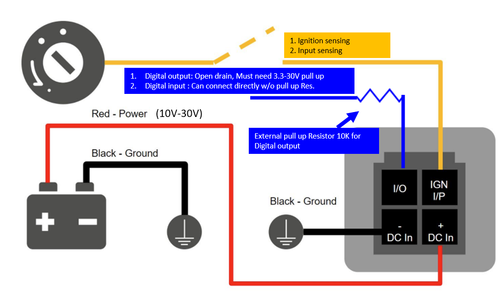
Function | Colour Wire | ||
| I/O | optional * | Brown |
IGN I/P | connected to positive feed on the ignition ** | Orange | |
DC IN | connected to permanent negative feed (ground) | Black | |
DC IN + | connected to permanent positive feed (power) | Red | |
* Currently not functional; will be used for additional features in future firmware. ** Connecting IGN I/P is optional and is needed only if the Ignition Sensing feature is configured. | |||
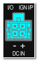
Connectivity diagram for devices with 4-pin connector
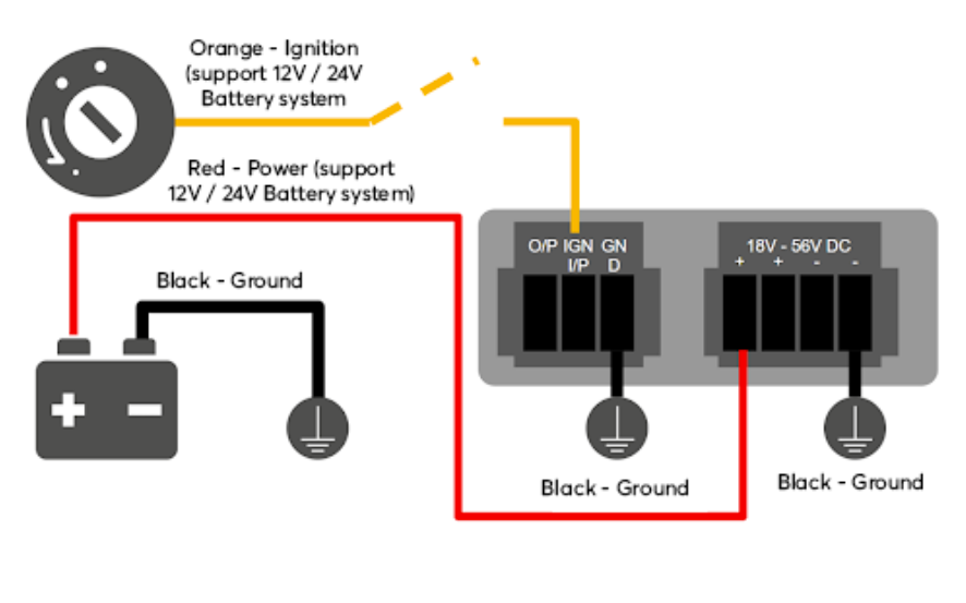
Connectivity diagram for devices with terminal block connection
GPIO Menu
Note: This feature is applicable for certain models that come with a GPIO interface.
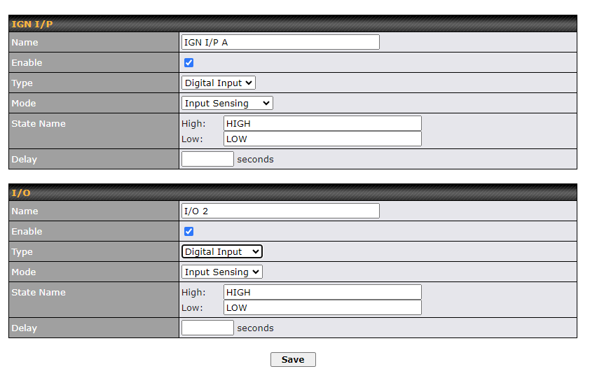
Ignition Sensing options can be found in Advanced > GPIO.
The configurable option for Ignition Input is Delay; the time in seconds that the router stays powered on after the ignition is turned off.
a.) Ignition sensing: 9-30V active high for IGN purpose
b.) Input Sensing: I/O input

The O/P (connected to the I/O pin on a 4 pin connector) can be configured as a digital input, a digital output, or an analog input.
Digital Input – the connection supports input sensing; it reads the external input and determines if the settings should be ‘High’ (on) or ‘Low’ (off).
Digital Output – when there is a healthy WAN connection, the output pin is marked as ‘High’ (on). Otherwise, it will be marked as ‘Low’ (off).
a.) Digital output:
Open drain for IO output. It is required to add an external pull up resistor of 10K for 3.3-30V pull up voltage.
(DO NOT exceed 250mA)
3.3-30V active high, 0.05-0.5V active low(mapping to 3.3-30V pull up voltage)
b.) Digital input: I/O input

Note: The Digital Output state (on/off) upon rebooting the device may vary depending on the model, e.g. MAX BR1 MK2 = Persistent; MAX Transit Mini with ContentHub = Reset to default, etc.
Analog Input – to be confirmed. In most cases, it should read the external input and determine the voltage level.
As of firmware 3.9.4, you can now configure a custom name for GPIO.
Name: Name to be shown in the Event Log
State Name: Tag name that represents the GPIO state to be shown in the Event Log