
6. Web Admin Configuration
6.1. Getting Started
To access the switch’s web interface without a DHCP uplink connection :
- 1.Power on the switch without an uplink connection.
- 2.Connect your laptop/PC to any of the switch ports.
- 3.Make sure your laptop/PC Ethernet connection is configured using the 192.168.1.0/24 network.
- 4.Open a web browser and enter the default Management IP address http://192.168.1.254 or https://192.168.1.254 to access the switch’s web admin interface.
Caution: The management IP address will no longer be 192.168.1.254 if the uplink connection is connected and the switch obtains a DHCP IP from the network.
To access the switch’s web interface with a DHCP uplink connection :
- 1.Connect the switch to your network and power it on.
- 2.Open a web browser on a device within the same network.
- 3.Check the client list on your main router’s web admin to determine the switch’s IP address on the network. If a Peplink router is used, this is the interface where you can check the client list.
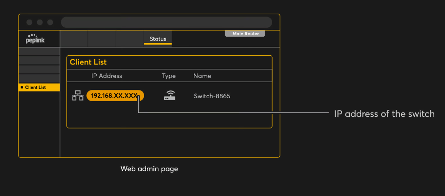
- 4.Enter the IP address of the switch’s web admin interface (http/https). You can obtain the IP address from the main router client list.
Log in with your credentials to access the interface.
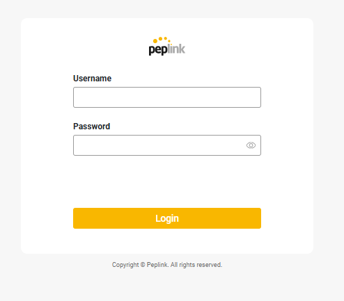
Log in with the default credentials:
Username: admin
Password: admin
This is the default admin user login for the Peplink Switch. The admin and read-only user passwords can be changed at System>Admin Security on InControl 2.
6.2. Device Connection Section
This section provides a summary of the settings and system information displayed on the Device Connection page.
6.2.1. External Access
- Mode: Shows the current network connection mode.
- Connection Type: Displays the type of connection the device is using, such as DHCP or Static IP.
- VLAN ID: Indicates the VLAN (Virtual Local Area Network) the device is assigned to.
- Port: Identifies the network port being used for the uplink connection.
- IP Address: Displays the IP address assigned to the device.
- Subnet Mask: Specifies the subnet configuration of the device, defining the network it belongs to.
- Default Gateway: Displays the gateway address used to route traffic outside the local network.
- Uptime: Shows how long the connection has been active since the last restart.
- DNS Servers: Lists the DNS servers the device is using to resolve domain names.
6.2.2. System Information
- Device Name: Displays the name assigned to the device for identification on the network.
- Model: Identifies the model of the device.
- Product Code: Displays the product code or SKU for the device.
- Hardware Revision: Indicates the hardware version of the device
- Serial Number: Shows the unique serial number of the device.
- Firmware Version: Displays the current firmware version installed on the device.
- Uptime: Indicates how long the device has been running since the last reboot.
- System Time: Displays the current time configured on the device.
- Diagnostic Report: Provides an option to download a report for diagnostics, which can be used for troubleshooting.
- Remote Assistance: Allows enabling remote access to the device for support purposes. This setting specifies the duration for which remote access will remain active.
6.2.3. MAC Address
- Switch MAC Address: Displays the device’s unique hardware address.
6.3. Uplink Configuration Section
This section explains how to configure the Uplink Settings for the device.
6.3.1. External Access Settings
- Mode:
- Auto: The device scans through all VLAN IDs (1-4094) and attempts to establish a connection using DHCP automatically. This mode is recommended for dynamic environments where VLAN and IP assignments are managed automatically.
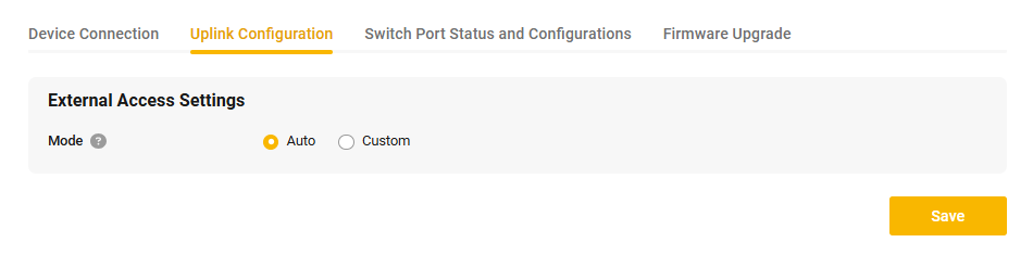
- Custom: Allows you to manually define the VLAN ID and specify the connection method (e.g., DHCP or Static IP). This mode is suitable for networks requiring specific configurations for connectivity.
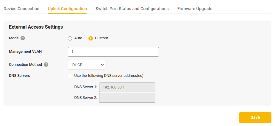
Custom Mode Configuration
When Custom Mode is selected under the External Access Settings, you can manually configure the uplink settings according to specific network requirements. Below are the configurable options:
- 1.Management VLAN
- Enter the VLAN ID that will be used for the device's management traffic.
- This allows the device to operate within a specific VLAN in your network setup.
- 2.Connection Method
- Select the method the device will use to obtain an IP address. The options include:
- DHCP: Automatically acquire an IP address from a DHCP server in the specified VLAN.
- Static IP: Manually set the IP address, subnet mask, and gateway. This is used when the network requires fixed addressing.
- Select the method the device will use to obtain an IP address. The options include:
- 3.DNS Servers
- If custom DNS settings are required, check the box to enable the Use the following DNS server address(es) option.
- Enter the preferred and alternate DNS server addresses:
- DNS Server 1: Specify the primary DNS server for name resolution.
- DNS Server 2: Optionally, specify a secondary DNS server as a fallback.
Caution: Before changing the Management VLAN, ensure that the switch port trunk/access port for the VLAN is configured first to avoid losing access to the switch via local access or IC2 access. A factory reset is required if the wrong Management VLAN is configured.
6.4. Switch Port Status and Configurations
This section provides an overview and customization options for the switch ports. It allows you to monitor the status and configure each port to meet specific network requirements.
6.4.1. Port Settings Overview
The interface displays a visual representation of the ports and their statuses, along with a detailed table for configuration.
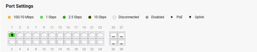
Port Indicators
- 100/10 Mbps (Yellow): Indicates the port is connected and operating at 10 or 100 Mbps.
- 1 Gbps (Light Green): Indicates the port is connected and operating at 1 Gbps.
- 2.5 Gbps (Green): Indicates the port is connected and operating at 2.5 Gbps.
- 10 Gbps (Dark Green): Indicates the port is connected and operating at 10 Gbps.
- Disconnected (Gray): Indicates the port is not connected to a device.
- Disabled (Dark Gray): Indicates the port has been manually disabled.
- PoE (Power over Ethernet): Displays whether the port supports PoE, providing power to connected devices like IP cameras or access points.
- Uplink: Highlights if the port is used as an uplink to connect to other network infrastructure.
Port Configuration Table
The table provides the following configuration options for each port:
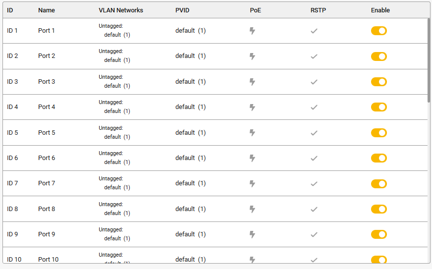
- ID: Displays the unique identifier for the port.
- Name: The user-defined name of the port.
- VLAN Networks: Lists the VLAN configurations associated with the port (tagged or untagged).
- PVID (Port VLAN ID): Displays the VLAN ID associated with untagged traffic on the port.
- PoE: Indicates if PoE is enabled on the port. An icon signifies PoE capability.
- RSTP (Rapid Spanning Tree Protocol): Shows whether RSTP is enabled to prevent loops in the network.
- Enable: Toggles the port on or off.
6.5. Firmware Upgrade
This section allows you to manage the device firmware, ensuring it is up-to-date for optimal performance and security. It includes options for checking updates, manual upgrades, and rebooting the device with a selected firmware.
6.5.1. Check for Updates
- Current Firmware Version: Displays the currently installed firmware version.
- Update: Click the Check for Updates button to automatically check for the latest firmware version available online. If an update is available, follow the prompts to install it.
6.5.2. Manual Upgrade
- Firmware Image: If you have downloaded a firmware file manually, click Choose File to upload it. Once uploaded, the device will apply the new firmware.
6.5.3. Reboot System
- Select Firmware: If the device has multiple firmware versions installed, you can choose which version to use during the next boot. Options include:
- Firmware 1: Select this to boot into an alternate firmware image.
- Firmware 2 (Running): The firmware is currently in use.
- Reboot Button: Click Reboot to restart the device and apply the selected firmware.