Peplink Balance and MediaFast Firmware Manual#
Peplink Products:
One / One Core / Two / 20 / 20X / 30 LTE / 30 Pro / 210 / 310 (HW4) / 310 (HW5) / 310X / 310 5G / 310 Fiber 5G / 305 / 380 / 380X / 580 / 580X (HW1) / 580X (HW2) / 710 / 1350 / 1350 EC / 2500 / 2500 EC / 5000 EC / EPX / SDX / SDX Pro / MediaFast 200 / 500 / 750
Peplink Balance Firmware 8.5.3
May 2026
Ch3. Advanced Feature Summary#
Drop-in Mode and LAN Bypass: Transparent Deployment
USB Modem and Android Tethering
Drop-in Mode and LAN Bypass: Transparent Deployment#
![]()
As your organization grows, it may require more bandwidth, but modifying your network can be tedious. In Drop-in Mode, you can conveniently install your Peplink router without making any changes to your network. For any reason your Peplink router looses power, the LAN Bypass will safely and automatically bypass the Peplink router to resume your original network connection.
QoS: Clearer VoIP#

VoIP and videoconferencing are highly sensitive to latency. With QoS, Peplink routers can detect VoIP traffic and assign it the highest priority, giving you crystal-clear calls.
Per-User Bandwidth Control#
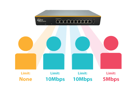
With per-user bandwidth control, you can define bandwidth control policies for up to 3 groups of users to prevent network congestion. Define groups by IP address and subnet, and set bandwidth limits for every user in the group.
High Availability via VRRP#
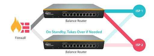
When your organization has a corporate requirement demanding the highest availability with no single point of failure, you can deploy two Peplink routers in High Availability mode. With High Availability mode, the second device will take over when needed.
USB Modem and Android Tethering#

For increased WAN diversity, plug in a USB LTE modem as backup. Peplink routers are compatible with over 200 modem types. You can also tether to smartphones running Android 4.1.X and above.
By default, the USB port is “USB Modem” mode. If you need to use it to connect to USB Ethernet Adapter, you need to change it to “USB Ethernet” mode,
https://forum.peplink.com/t/can-i-use-ethernet-adapters-on-the-usb-wan/8327
Built-In Remote User VPN Support#
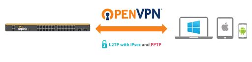
Use OpenVPN or L2TP with IPsec to safely and conveniently connect remote clients to your private network. L2TP with IPsec is supported by most devices, but legacy devices can also connect using PPTP.
Click here for the full instructions on setting up L2TP with IPsec.
Click here for the full instructions on setting up OpenVPN connections
LACP NIC Bonding#
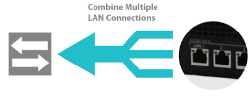
Use 802.3ad to combine multiple LAN connections into a virtual LAN connection. This virtual connection has higher throughput and redundancy in case any single link fails.
KVM Virtualization#
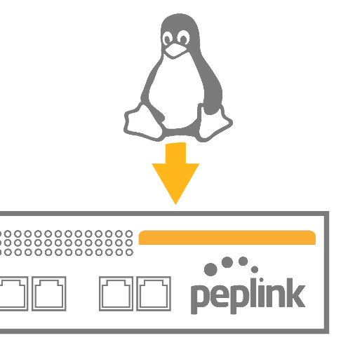
KVM is a virtualisation module that allows administrators using our routers to host a large range of virtual machines. KVM is now supported by some of the MediaFast / ContentHub routers.
Click here for the full instructions on how to set up KVM
Click here for the full instructions on how to set up KVM with USB Storage
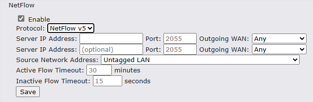
NetFlow#
NetFlow protocol is used to track network traffic. Tracking information from NetFlow can be sent to the NetFlow collector, which analyzes data and generates reports for review.
Note: To enable this feature, go to https://<Device’s IP>/cgi-bin/MANGA/support.cgi
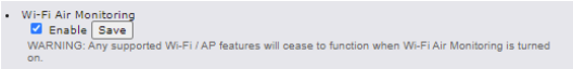
Wi-Fi Air Monitoring#
Peplink routers support Wi-Fi “Air Monitoring Mode” which is used to troubleshoot remotely and proactively monitor Wi-Fi and WAN performance. After enabling Wi-Fi Air Monitoring, reports can be viewed under InControl 2 > Reports > AirProbe Reports.
Note: To enable this feature, go to https://<Device’s IP>/cgi-bin/MANGA/support.cgi
Ch5. Peplink Balance Overview#
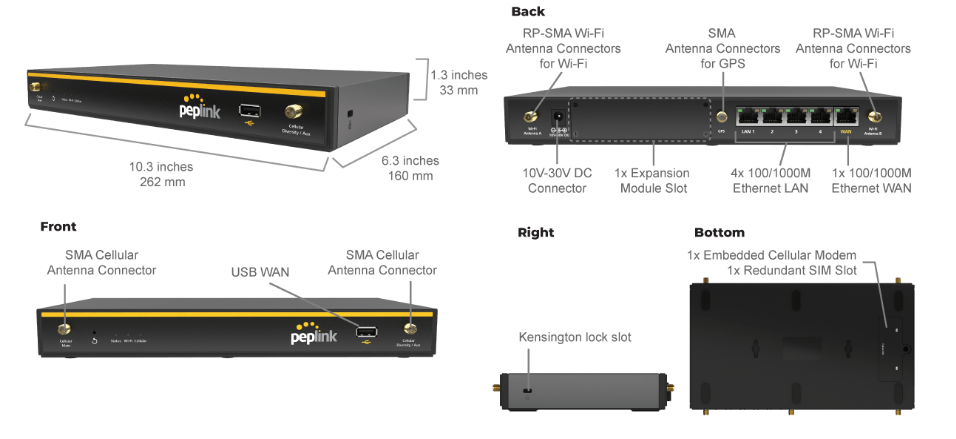
Peplink Balance 20X#
Panel Appearance#
Flex Module Mini#

| 1x LTE-A Module | |
| Interface | 1x Embedded LTE-A Cellular Modems with Redundant SIM Slots |
| Antenna Connectors | 2x SMA Cellular Antenna Connectors |
| Downlink / Uplink Datarate | 300Mbps/50Mbps (CAT-6)
600Mbps/150Mbps (CAT-12) |
| Power Consumption | 10W |
| Weight | 0.83 pounds | 375 grams |

| 1xLTE-A Module | |
| Interface | 1x Embedded LTE-A Cellular Modems with Redundant SIM Slots |
| Antenna Connectors | 4x SMA Cellular Antenna Connectors |
| Downlink / Uplink Datarate | 1.2 Gbps/150 Mbps (CAT-18) |
| Power Consumption | 10W |
| Weight | 0.83 pounds | 375 grams |
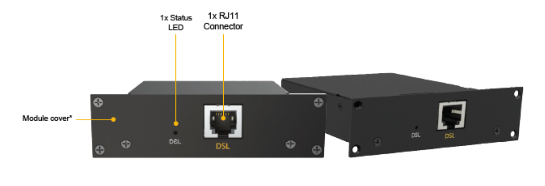
| 1x VDSL Module | |
| Interface | 1x RJ11 Connector,
1x Status LED |
| Power Consumption | 9W |
| Weight | 0.44 pounds | 200 grams |
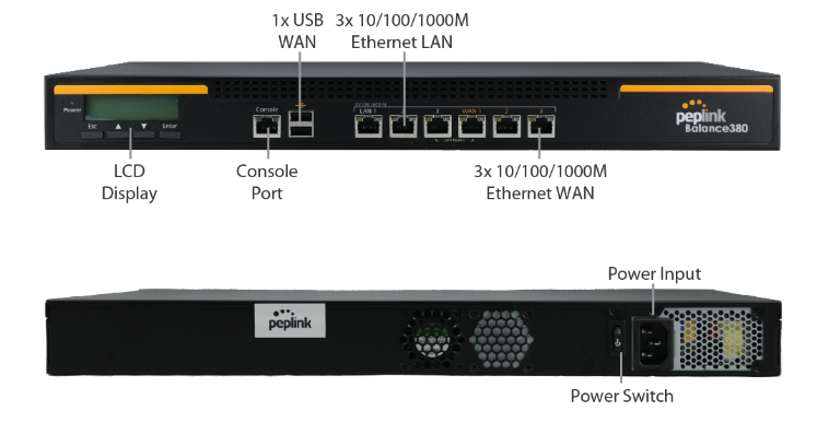
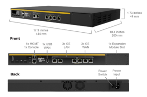
Peplink Balance 380X#
Panel Appearance#
Flex Module Mini#

| 1x LTE-A Module | |
| Interface | 1x Embedded LTE-A Cellular Modems with Redundant SIM Slots |
| Antenna Connectors | 2x SMA Cellular Antenna Connectors |
| Downlink / Uplink Datarate | 300Mbps/50Mbps (CAT-6)
600Mbps/150Mbps (CAT-12) |
| Power Consumption | 10W |
| Weight | 0.83 pounds | 375 grams |

| 1xLTE-A Module | |
| Interface | 1x Embedded LTE-A Cellular Modems with Redundant SIM Slots |
| Antenna Connectors | 4x SMA Cellular Antenna Connectors |
| Downlink / Uplink Datarate | 1.2 Gbps/150 Mbps (CAT-18) |
| Power Consumption | 10W |
| Weight | 0.83 pounds | 375 grams |
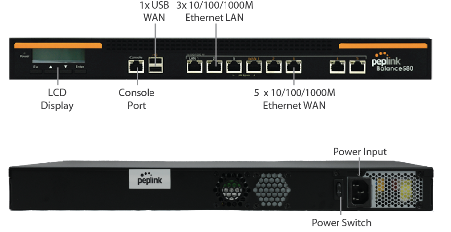
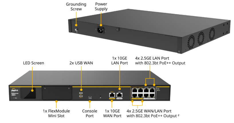
Peplink Balance 580X (HW1 & HW2)#
Panel Appearance#
Balance 580X (HW1):
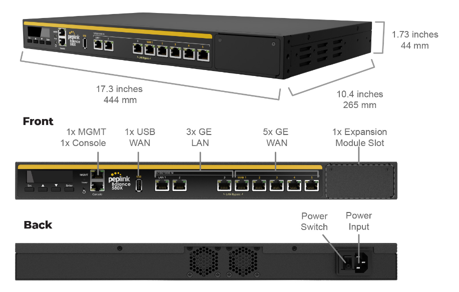
Balance 580X (HW2):
Flex Module Mini#

| 1x LTEA Module | |
| Interface | 1x Embedded LTE-A Cellular Modems with Redundant SIM Slots |
| Antenna Connectors | 2x SMA Cellular Antenna Connectors |
| Downlink / Uplink Datarate | 300Mbps/50Mbps (CAT-6)
600Mbps/150Mbps (CAT-12) |
| Power Consumption | 10W |
| Weight | 0.83 pounds | 375 grams |

| 1xLTEA Module | |
| Interface | 1x Embedded LTE-A Cellular Modems with Redundant SIM Slots |
| Antenna Connectors | 4x SMA Cellular Antenna Connectors |
| Downlink / Uplink Datarate | 1.2 Gbps/150 Mbps (CAT-18) |
| Power Consumption | 10W |
| Weight | 0.83 pounds | 375 grams |
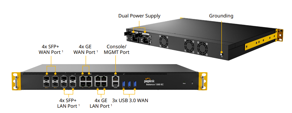
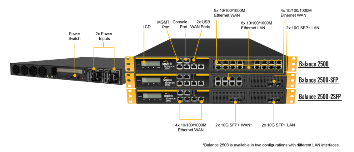
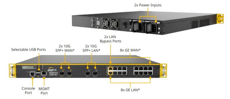
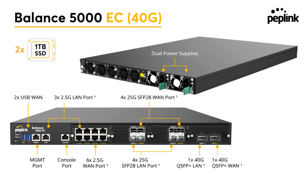
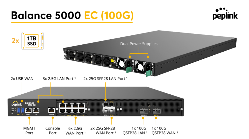
Peplink Balance 5000 EC#
Panel Appearance#
Balance 5000 EC (40G)
Balance 5000 EC (100G)
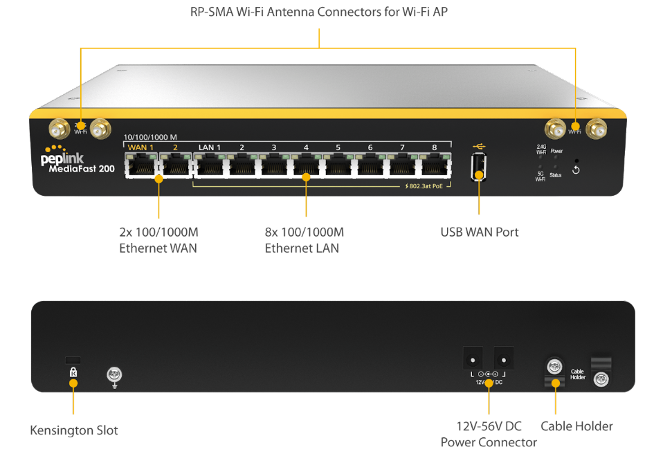
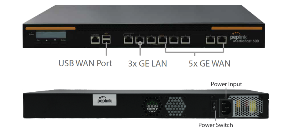
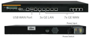
Ch6. Peplink MediaFast Overview#
Ch7. Peplink Flex-Module Supported Models#
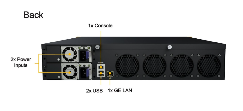
Peplink EPX#
The EPX is a rapidly deployable, powerful, and versatile SD-WAN router that connects a wide range of WAN options from LTE-A, satellite modems, to fixed line networks this can be used simultaneously to allow bonding using our SpeedFusion technology.
With its modular construction, the EPX is suitable for any deployment.
Panel Appearance#
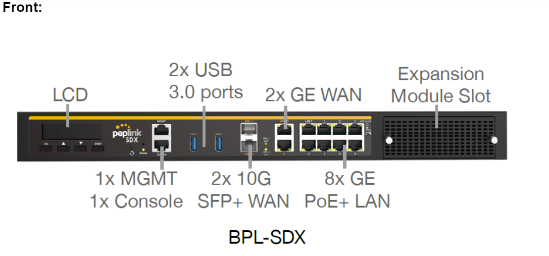
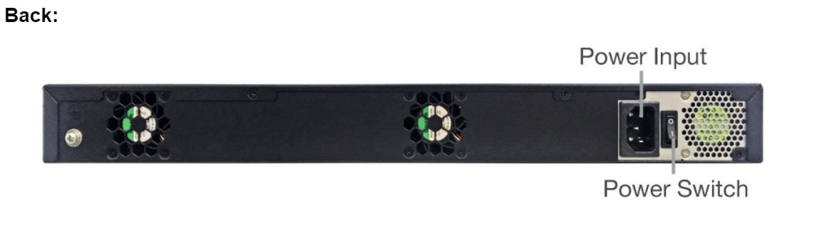
Peplink SDX#
The SDX is a Modular Enterprise Grade Router. In addition to popular features such as SpeedFusion SD-WAN and InControl centralized management, the SDX has an expandable module that you can change according to your needs.
The SDX includes two integrated SFP+ WAN Ports, as well as eight PoE-enabled LAN Ports.
These ports are available no matter which module you use.
Panel Appearance#
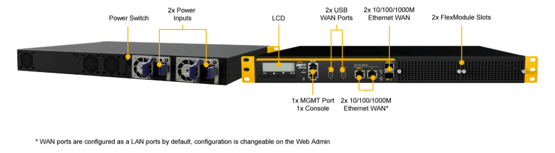
Peplink SDX Pro#
In addition to the power of the SDX, the SDX Pro offers greater flexibility and functionality. It has two FlexModule slots, enabling you to customize the device with different modules to suit any deployment. It supports edge computing so it can deliver websites, applications, and docker containers to connected devices.
Panel Appearance#
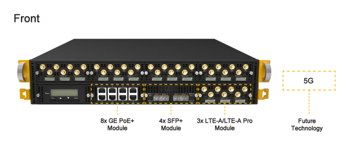
Flex Module Expansion Modules#
8x GE PoE+ Module (EXM-8C)#
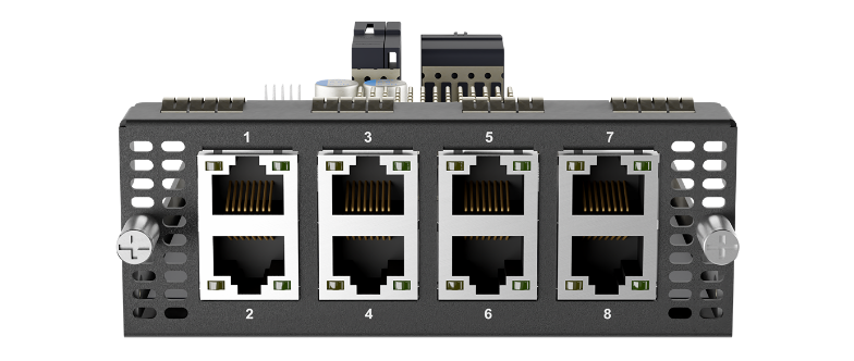
| 8x GE PoE Module | |
| Interface | 8x 10/100/1000M Ethernet Ports *
Capable of PoE+ |
| Power Consumption | 15W (255W max. with 802.3at/af PoE+ Output) |
| Dimensions | 4.1 x 7.4 x 1.5 inches
103 x 188 x 38 mm |
| Weight | 1.1 pounds (475 grams) |
* Module can be configured with LAN or WAN ports as needed.
LED Indicator:
| Ethernet Ports | |
| Right LED | Orange – Enabled as WAN port |
| OFF – Enabled as LAN port | |
| Left LED | Solid – Port is connected without traffic |
| Blinking – Data is transferring | |
| OFF – Port is not connected | |
| Port Type | Auto MDI/MDI-X ports |
4x SFP+ Module (EXM-4F)#

| 4x SFP+ Module | |
| Interface | 4x SFP+ Ports * |
| Power Consumption | 11W |
| Dimensions | 4.1 x 7.4 x 1.5 inches
103 x 188 x 38 mm |
| Weight | 0.83 pounds (375 grams) |
3x LTE-A Module (EXM-3LTEA)#
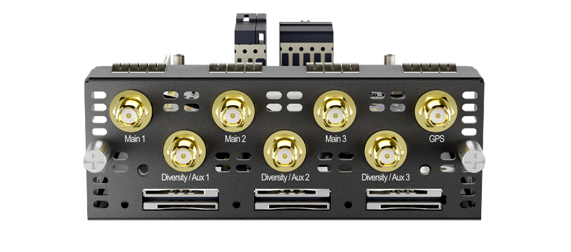
| 3x LTE-A Module | |
| Interface | 3x Embedded LTE-A Cellular Modems with Redundant SIM Slots |
| Antenna Connectors | 6x SMA Cellular Antenna Connectors
1x SMA GPS Antenna Connector |
| Power Consumption | 20W |
| Dimensions | 4.1 x 7.4 x 1.5 inches
103 x 188 x 38 mm |
| Weight | 0.83 pounds (375 grams) |
4x LTE-A Module (EXM-4LTEA)#
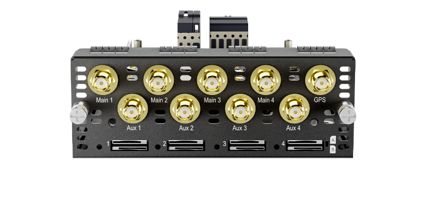
| 3x LTE-A Module | |
| Interface | 4x Embedded LTE-A Cellular Modems with Redundant SIM Slots |
| Antenna Connectors | 8x SMA Cellular Antenna Connectors
1x SMA GPS Antenna Connector |
| Power Consumption | 20W |
| Dimensions | 4.1 x 7.4 x 1.5 inches
103 x 188 x 38 mm |
| Weight | 0.83 pounds (375 grams) |
CAT-18. 2x LTE-A Module (EXM-2GLTE-G)#

| 2x LTE-A Module | |
| Interface | 2x Embedded LTE-A Cellular Modems with Redundant 4FF Nano SIM Slots |
| Antenna Connectors | 8x SMA Cellular Antenna Connectors
1x SMA GPS Antenna Connector |
| Power Consumption | 20W |
| Dimensions | 4.1 x 7.4 x 1.5 inches
103 x 188 x 38 mm |
| Weight | 0.83 pounds (375 grams) |
SIM Injector FlexModule (EXM-SIM-BK56)#
* Compatible with EPX, SDX Pro
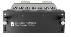
| SIM Injector FlexModule | |
| SIM Slot Capacity | 56 4FF Nano SIM Cards |
| Power Consumption | 15W |
| Dimensions | 4.1 x 7.4 x 1.5 inches
103 x 188 x 38 mm |
| Weight | 1.30 pounds (600 grams) |
2x 5G Module (EXM-2X5GD)#

| 2x 5G Module | |
| Interface | 2x Embedded Cellular Modems with Redundant 4FF Nano SIM Slots |
| Antenna Connectors | 8x SMA Cellular Antenna Connectors
1x SMA GPS Antenna Connector |
| Power Consumption | 20W |
| Dimensions | 4.1 x 7.4 x 1.5 inches
103 x 188 x 38 mm |
| Weight | 0.83 pounds (375 grams) |
Ch8. OLED Display Menu#
> HA State: Master/Slave

> LAN IP
> VIP
> System Status
> System
> Firmware ver. (shows firmware version)
> Serial number (shows serial number)
> System time (shows current time)
> System uptime (shows system uptime since last reboot)
> CPU load (shows current CPU loading, 0-100%)
> LAN
> Status (shows LAN port physical status)
> IP address (shows LAN IP address)
> Subnet mask (shows LAN subnet mask)
> Link status (shows Connected/Disconnected, IP address list)
> WAN1
> WAN2
> WAN3*
> VPN status (shows Connected/Disconnected)
>VPN Profile 1
>VPN Profile 2
>…
>VPN Profile n
> Link usage
>Throughput in (shows transfer rate in Kbps)
> WAN1
> WAN2
> WAN3*
> Throughput out (shows transfer rate in Kbps)
> WAN1
> WAN2
> WAN3*
> Data Transfered (shows volume transferred since last reboot in MB)
> WAN1
> WAN2
> WAN3*
> Maintenance
> Reboot > Reboot? (Yes/No) (to reboot the unit)
> Factory default > Factory default? (Yes/No) (to restore factory defaults)
> LAN config
> Port speed (shows port speed: Auto, 10baseT-FD, 10baseT-HD, 100baseTx-FD, 100baseTx-HD, 1000baseTx-FD)
> LAN
> WAN1
> WAN2
> WAN3*
*Layout continues as such for all available WAN ports
Ch10. Basic Configuration#
Connecting to the Web Admin Interface#
Start a web browser on a computer that is connected with the Peplink Balance through the LAN.
To connect to the web admin of the Peplink Balance, enter the following LAN IP address in the address field of the web browser:
https://192.168.1.1
(This is the default LAN IP address of the Peplink Balance.) Enter the following to access the web admin interface.
Username: admin
Password: admin
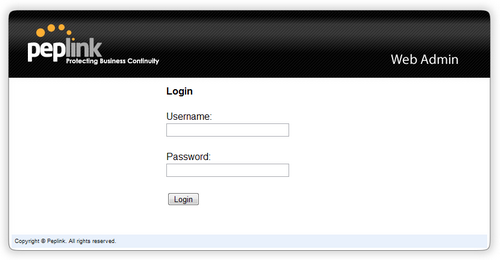
(This is the default admin user login of the Peplink Balance. )
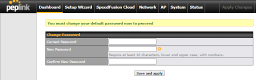
You must change the default password on the first successful logon.
Password requirements are: A minimum of 10 lower AND upper case characters, including at least 1 number.
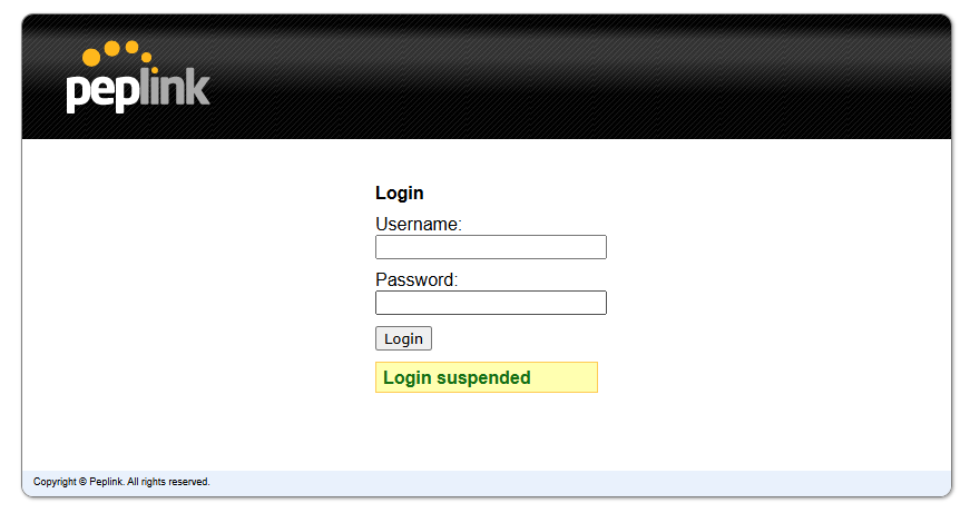
When HTTP is selected, the URL will be redirected to HTTPS by default.
Login will be suspended for 5 minutes after attempting to log in with an “Invalid Username or Password.”
After successful login, the Dashboard of the web admin interface will be displayed.
| Important Note |
| The Save button causes the changes to be saved. Configuration changes (e.g., WAN, LAN, admin settings, etc.) take effect after clicking the Apply Changes button on each page’s top-right corner. |
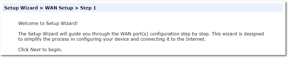
Configuration with the Setup Wizard#
The Setup Wizard simplifies the task of configuring WAN connection(s) by guiding the configuration process step-by-step.
To begin, click Setup Wizard after connecting to the web admin interface.

Click Next >> to begin.
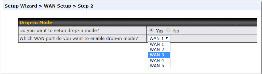
Select Yes if you want to set up drop-in mode using the Setup Wizard.
Click on the appropriate checkbox(es) to select the WAN connection(s) to be configured. If you have chosen to configure drop-in mode using the Setup Wizard, the WAN port to be configured in drop-in mode will be checked by default.
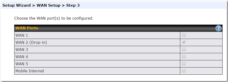
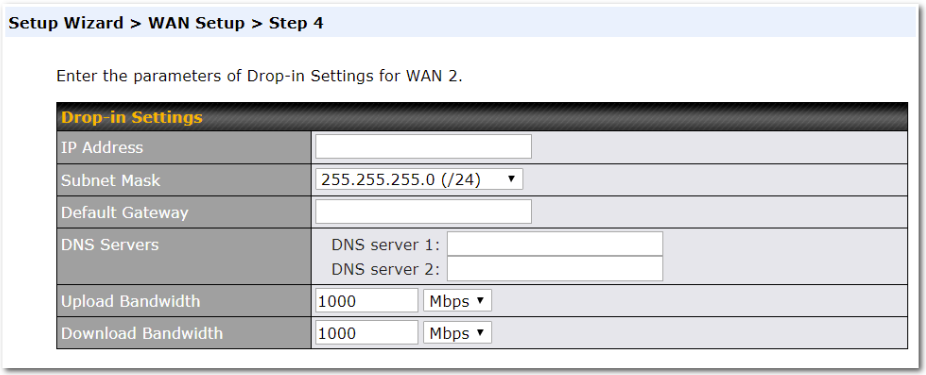
If drop-in mode is going to be configured, the setup wizard will move on to Drop-in Settings.
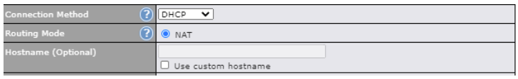
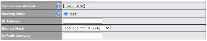
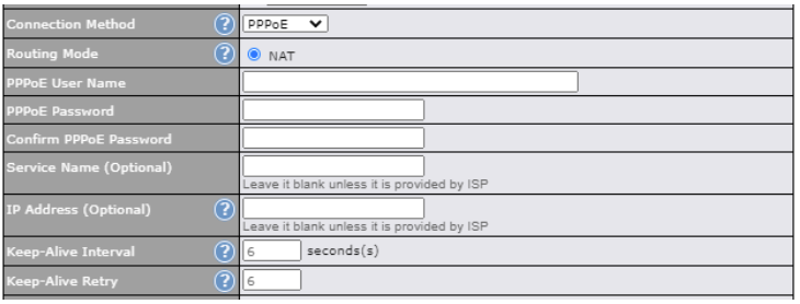
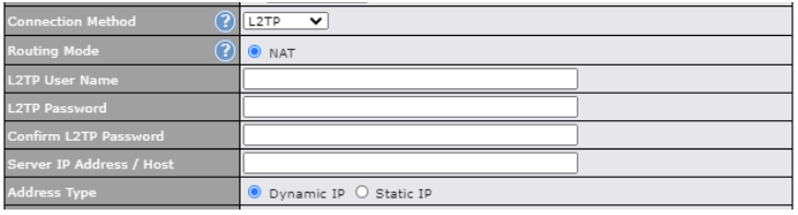
If you are not using drop-in mode, select the connection method for the WAN connection(s) from the following screen:
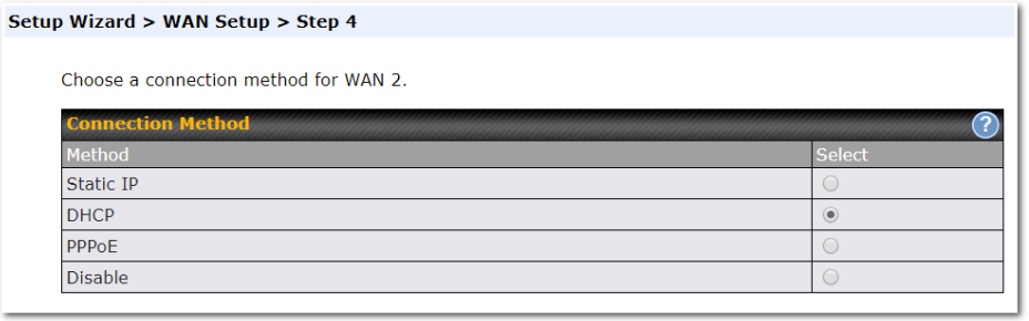
Depending on the selection of connection type, further configuration may be needed. For example, PPPoE and static IP require additional settings for the selected WAN port. Please refer to Section 13, Configuring the WAN Interface(s) for details on setting up DHCP, static IP, and PPPoE.
If Mobile Internet Connection is checked, the setup wizard will move on to Operator Settings.
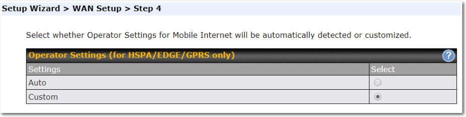
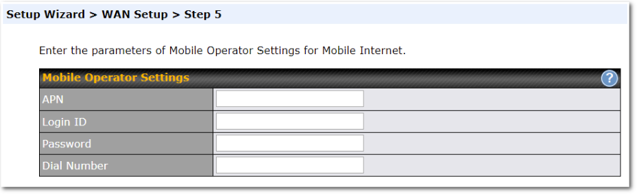
If Custom Mobile Operator Settings is selected, APN parameters are required. Some service providers may charge a fee for connecting to a different APN. Please consult your service provider for the correct settings.
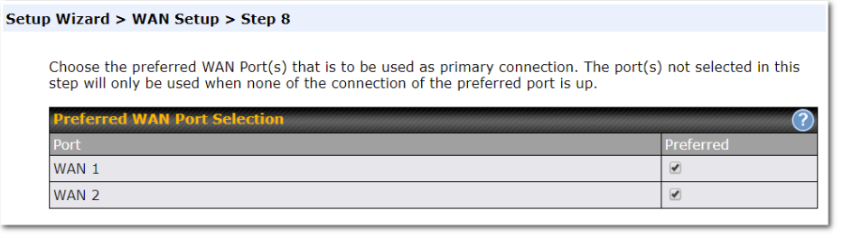
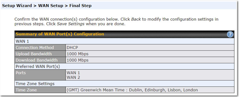
Click on the appropriate check box(es) to select the preferred WAN connection(s). Connection(s) not selected in this step will be used as a backup only. Click Next >> to continue.
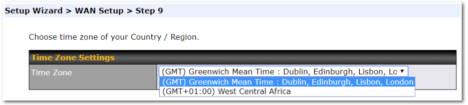
Choose the time zone of your country/region. Check the box Show all to display all time zone options.
Check in the following screen to make sure all settings have been configured correctly, and then click “Save Settings” to confirm.
After finishing the last step in the setup wizard, click Apply Changes on the page header to allow the configuration changes to take effect.
Ch11. SpeedFusion Connect#
With Peplink products, your device is able to connect to SpeedFusion Connect without the use of a second endpoint. This service has wide access to a number of SpeedFusion endpoints hosted from around the world, providing your device with unbreakable connectivity wherever you are.*

*SpeedFusion Connect is supported in firmware version 8.1.0 and above. SpeedFusion Connect is a subscription basis. SpeedFusion Connect license can be purchased at https://estore.peplink.com/ > SpeedFusion Service > SpeedFusion Connect.
Enable SpeedFusion Connect#
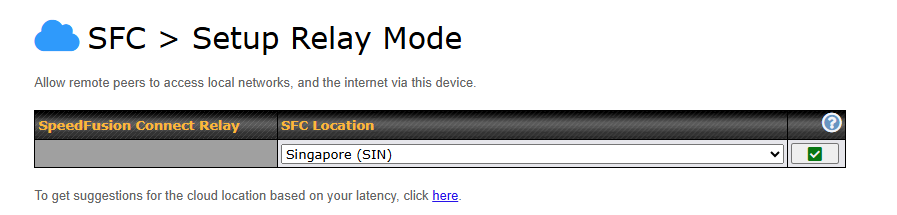
Access the Web Admin of the device you want to create as the Peplink Relay Server, navigating to the “SFC Protect” tab.
To setup a Peplink Relay Mode, select “Relay Mode – for Inbound accesses” > Choose the SFC Protect Location you wish to connect to > Click on the Green tick button to confirm the change.
User may also get the suggestions cloud location based on latency by click “here”.
The Protect private networks option blocks traffic from Relay Clients to private IP address ranges, including:
- 10.0.0.0/8
- 100.64.0.0/10
- 172.16.0.0/12
- 192.168.0.0/16
- 169.254.0.0/16
Enabling this option prevents access to these private networks from Relay Clients to protect your private networks and devices. This can improve the security of your local network against unwanted traffic from Relay Clients.
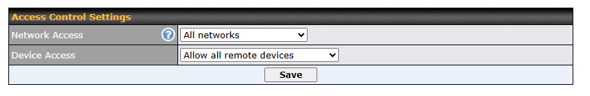
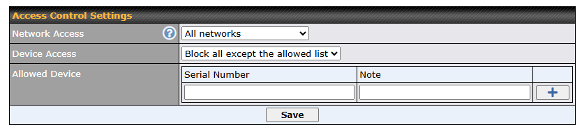
To block other devices from connecting, select “Block all except the allowed list” and add allowed devices serial number under the list.
The Relay Sharing Code will be generated, and other peers can use this code to establish a SpeedFusion Connect Protect that will forward the traffics to this device, allowing them to access local networks and the internet via your WAN connection.

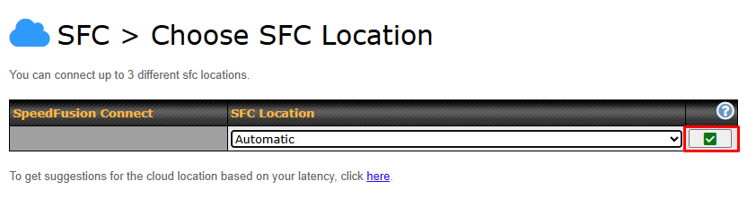
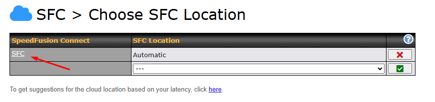
To connect to SpeedFusion Connect Protect, you can select a SFC Protect Location of your choice, or simply and Automatic then the device will establish connection to the neareset SFC Protect server.
Choose Automatic > Click on the green tick button to confirm the change.
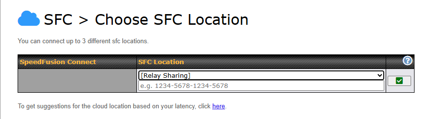
Or you may select Relay Sharing and use your Relay Sharing Code to create a profile if you have set up a Peplink Relay Client on another device.
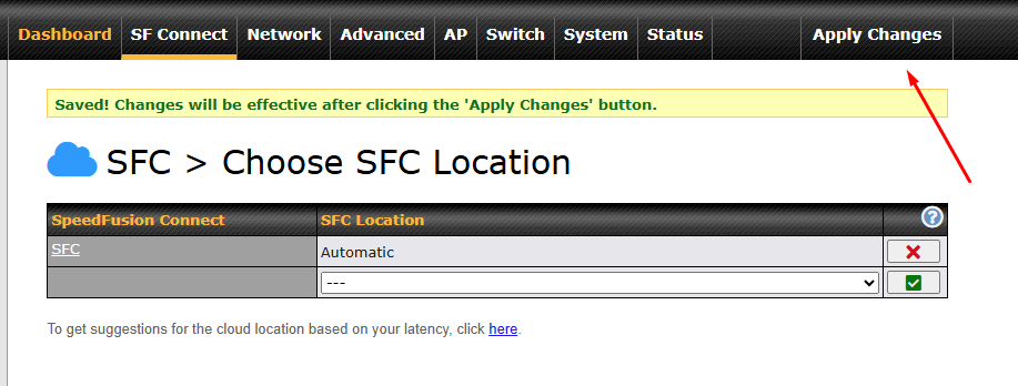
Click on Apply Changes to save the change.
By default, the router will build a SpeedFusion tunnel to the SpeedFusion Connect Protect.
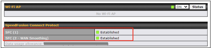
If you are running a latency sensitive service like video streaming or VOIP, a WAN Smoothing sub-tunnel can be created. Navigate to Navigate to SFC Protect > Client Mode – for Outbound accesses > SFC.
A SpeedFusion Connect Protect Profile configuration window will pop out. Click on the + sign to create the WAN Smoothing sub-tunnel.

Click on Save and Apply Changes to save the configuration. Now, the router has 2 Speedfusion tunnels to the SpeedFusion Connect Protect.
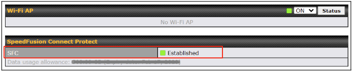
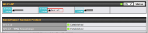
Data usage allowance is able to check from the below SpeedFusion Connect from Dashboard.
| Status | |
|---|---|
| Data usage allowance: [remaining data] (Expiry date: 2026 | Remaining SFC data usage occurs. |
| Fair usage policy (Expiry date: 2026) | Device with active care plan but exceeded SFC data usage. This mode will reduce the throughput to 10 Mbps |
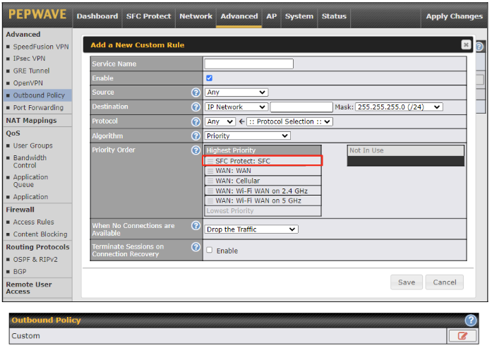
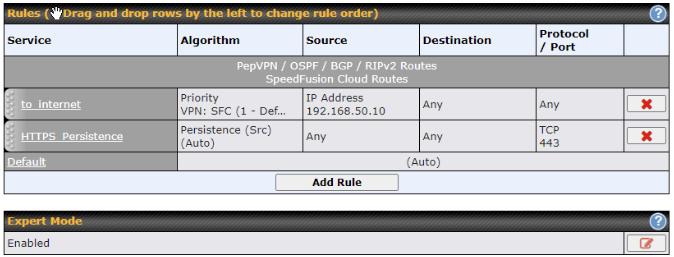
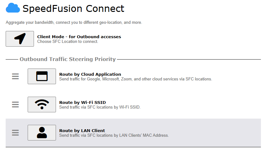
Create an outbound policy to steer the internet traffic to go into SFC Protect. Please go to Advanced > Outbound Policy, click on Add Rule to create a new outbound policy.
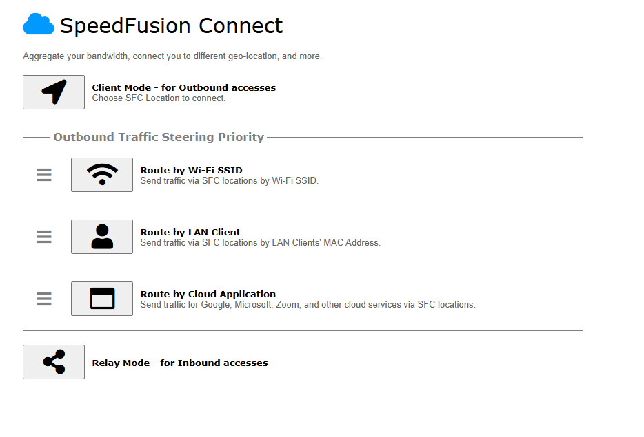
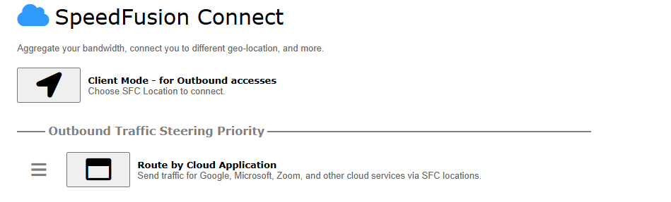
Route by Cloud Application#
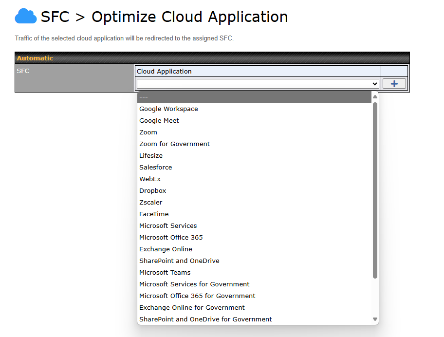
Optimize Cloud Application allows you to route Internet traffic through SpeedFusion Connect Protect based on the application. Go to SFC Protect > Route by Cloud Application.
Select a Cloud application to route through SpeedFusion Connect Protect from the drop down list > Click ![]() > Save > Apply Changes.
> Save > Apply Changes.
Click the ![]() to remove a selected Cloud application from routing through SpeedFusion Connect Protect.
to remove a selected Cloud application from routing through SpeedFusion Connect Protect.
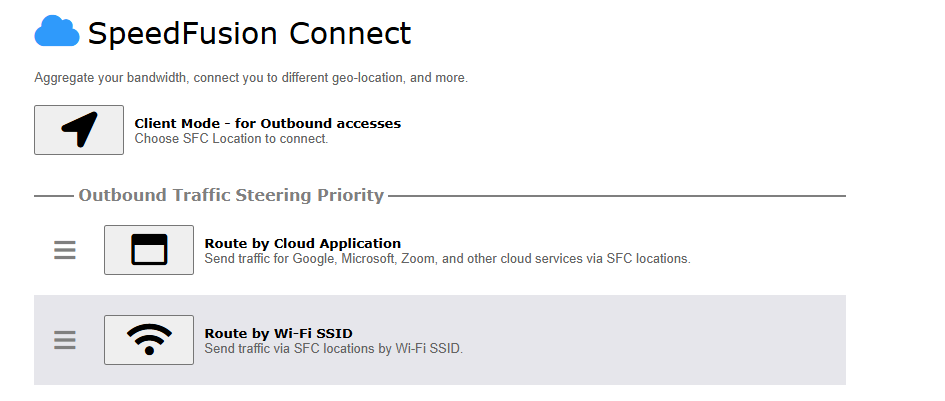
Route by Wi-Fi SSID#
SpeedFusion Connect Protect provides a convenient way to route the Wi-Fi client to the cloud from SFC Protect > Route by Wi-Fi SSID.
Create a new SSID for SFC Protect. The new SSID will inherit all settings from one of the existing SSIDs including the Security Policy. Then click Save followed by Apply Changes.

SFC Protect SSID will be shown on Dashboard.
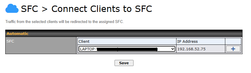
Route by LAN Client#
SpeedFusion Connect Protect provides a convenient way to route the LAN client to the cloud from SFC Protect > Route by LAN Client.
Choose a client from the drop down list > Click + > Save > Apply Changes.
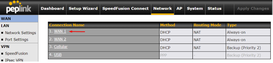
Ch12. Network Tab#
WAN#
From Network > WAN, choose a WAN connection by clicking it.
IPv6 #
You can also enable IPv6 support in this section.

DNS over HTTPS (DoH) #
You can enable the DoH support in this section.
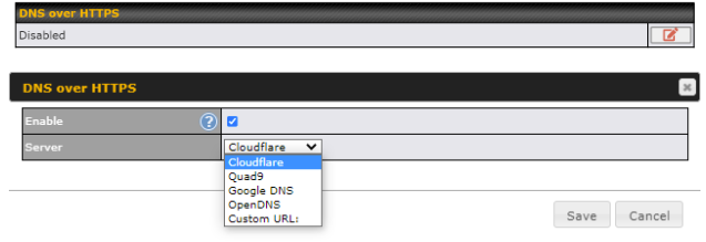
| DNS over HTTPS | |
| Enable | When this option is enabled, the DNS proxy server will use HTTPS connections to forward DNS requests to the DoH resolver; it will not fallback to traditional UDP DNS options. |
| Server | The options to configure DoH with a predefined server are:
|
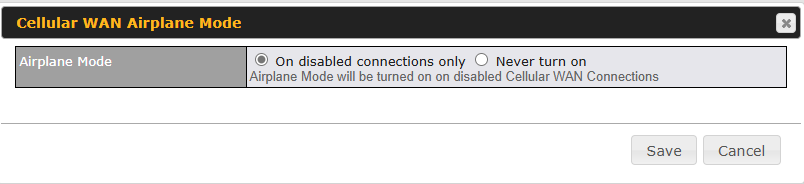
Cellular WAN Airplane Mode#
Cellular WAN Airplane Mode

You can enable Airplane Mode in this section (Network > WAN). Airplane mode will be turned ON when Cellular WAN Connections are disabled.
WAN Quality Monitoring#
This settings advice how WAN Quality information is being gathered.

By default, WAN Quality will always be observed and gathered automatically. With customized choice of WAN connections, the device will always observe WAN Quality of those selected WAN connections. Other WAN connections may stop observing WAN Quality information if it is not necessary for the underlying features.
Synergy Mode#
You can enable the Synergy Controller in this section.

You may click this ![]() to enable the Synergy Controller. By default, the setting is disabled.
to enable the Synergy Controller. By default, the setting is disabled.
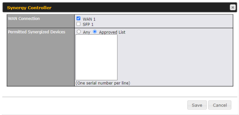
You may select the WAN connection to use as a Synegy Link which will connect to synergized devices.
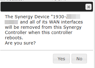
User may now remove synergy device from synergy controller Web Admin “Network > WAN > Synergy Controller > Synergized Devices(s)”
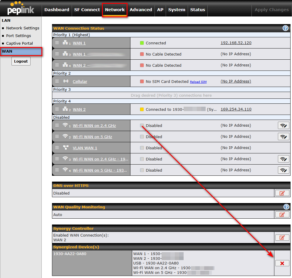
A confirmation message will pop up and click “Yes” to confirm the removal action.
Starlink WAN#
Starlink WAN
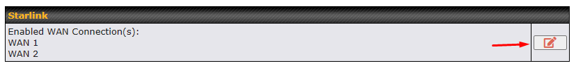
On supported models (refer to Firmware 8.4.0 – Release Notes, #30479), under the WAN settings page, users can see the option for Starlink at the bottom of the page.
To choose the WAN port for connecting to Starlink equipment, click the ‘EDIT’ (![]() ) icon as shown below:
) icon as shown below:
The ‘Starlink – WAN Connection’ selection will pop up, displaying the available options below.
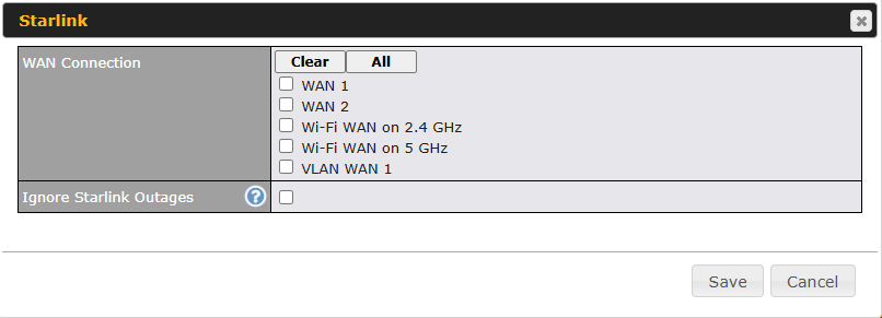
| Starlink | |
| WAN connection | WAN option to enable Starlink management. |
| Ingnore Starlink Outages | Enable the device to ignore all outages (e.g., obstructed, no downlink, no pings).
The WAN will only go down when its health check fails. |
WAN Connection Settings (Ethernet)#
Clicking an Ethernet WAN connection will result in the following screen:
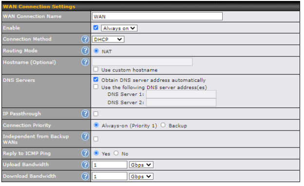
| WAN Connection Settings | |
| WAN Connection Name | Enter a name to represent this WAN connection. |
| Enable | This setting enables the WAN connection. If schedules have been defined, you will be able to select a schedule to apply to the connection. |
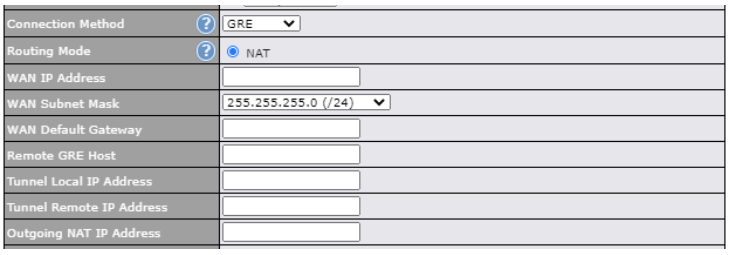
| Connection Method | There are five possible connection methods for Ethernet WAN:
|
| Routing Mode | This field shows that NAT (network address translation) will be applied to the traffic routed over this WAN connection. IP Forwarding is available when you click the link in the help |
| Hostname (Optional) | If your service provider’s DHCP server requires you to supply a hostname value upon
acquiring an IP address, you may enter the value here. If your service provider does not provide you with a hostname, you can safely bypass this option. |
| Management IP Address | Management IP Address is available for configuration when you click the link in the help This option allows you to configure the management IP address for the DHCP WAN connection. |
| DNS Servers | Each ISP may provide a set of DNS servers for DNS lookups. This setting specifies the
DNS (Domain Name System) servers to be used when a DNS lookup is routed through this connection. Selecting Obtain DNS server address automatically results in the DNS servers assigned by the WAN DHCP server being used for outbound DNS lookups over the connection. (The DNS servers are obtained along with the WAN IP address assigned by the DHCP server.) When the following DNS server address(es) is selected, you may enter custom DNS server addresses for this WAN connection into the DNS server 1 and DNS server 2 fields. |
| Connection Priority | This option allows you to configure the WAN connection whether for normal daily usage or as a backup connection only.
If Always-on is chosen, the WAN connection will be kept on continuously, regardless of the priority of other WAN connections. If Backup is chosen, the WAN connection will depend on other WAN connections. It will not be used when one or more higher priority dependent WAN connections are connected. |
| Independent from Backup WANs | If this is checked, the connection will be working independent from other Backup WAN connections. Those in Backup Priority will ignore the status of this WAN connection, and will be used when none of the other higher priority connections are available. |
| Reply to ICMP PING | If the checkbox is unticked, this option is disabled and the system will not reply to any ICMP ping echo requests to the WAN IP addresses of this WAN connection.
Default: ticked (Yes) |
| Upload Bandwidth | This field refers to the maximum upload speed.
This value is referenced when default weight is chosen for outbound traffic and traffic prioritization. A correct value can result in effective traffic prioritization and efficient use of upstream bandwidth. |
| Download Bandwidth | This field refers to the maximum download speed.
Default weight control for outbound traffic will be adjusted according to this value. |
WAN Connection Settings (Cellular)#
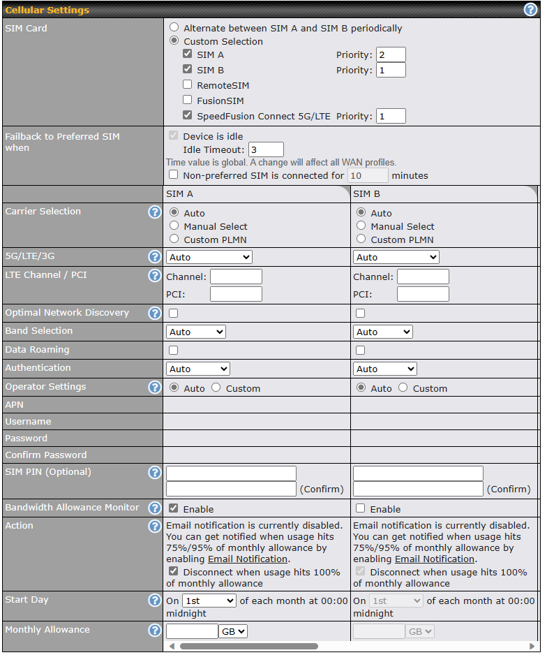
| Cellular Settings | |
| SIM Card | If “Alternate between SIM A and SIM B periodically” is selected, the SIM card will be switching according to the schedule time in the SIM Cards Alternate.
If “Custom Selection” is selected, you can designate the priority of the SIM cards (SIM A/ SIM B/ Remote SIM/ SpeedFusion Connect) and connect to. For routers that support the SIM Injector, you may select the “Remote SIM” to provision a SIM from a SIM Injector. Further details on the SIM Injector found is available here: https://www.peplink.com/products/sim-injector/. |
| Fallback to Prefered SIM when | This option is allowing to switch to another SIM cards when the Cellular WAN reached faillback timeout. |
| SIM Cards Alternate | If “Alternate between SIM A and SIM B periodically” is selected in the SIM Card section, the SIM Cards Alternate will be shown:
You may set the schedule time for for switching between SIM A only and SIM B only. |
| Carrier Selection | This drop-down menu allows restricting network on particular carrier. Click the “?” button to choose the manual select or custom PLMN. |
| 5G/LTE/3G | This drop-down menu allows restricting cellular to particular band. Click the “?” button to enable the selection of specific bands. |
| LTE Channel / PCI | Channel and PCI are required to restrict LTE network. Can be ignore if wanted to remove restriction. |
| Optimal Network Discovery | Cellular WAsN by default will only handover from 3G to LTE network when there is no active data traffic, enable this option will make it run the handover procedures after fallback to 3G for a defined effective period, even this may interrupt the connectivity for a short while. |
| Band Selection | When set to Auto, band selection allows for automatically connecting to available, supported bands (frequencies) .
When set to Manual, you can manually select the bands (frequencies) the SIM will connect to. |
| Data Roaming | This checkbox enables data roaming on this particular SIM card. When data roaming is enabled this option allows you to select in which countries the SIM has a data connection. The option is configured by using MMC (country) codes.Please check your service provider’s data roaming policy before proceeding. |
| Authentication | Choose from PAP Only or CHAP Only to use those authentication methods exclusively. Select Auto to automatically choose an authentication method. |
| Operator Settings | This setting allows you to configure the APN settings of your connection. If Auto is selected, the mobile operator should be detected automatically. The connected device will be configured and connection will be made automatically. If there is any difficulty in making connections, you may select Custom to enter your carrier’s APN, Login, Password, and Dial Number settings manually. The correct values can be obtained from your carrier. The default and recommended setting is Auto. |
| APN / Login / Password / SIM PIN | When Auto is selected, the information in these fields will be filled automatically. Select Custom to customize these parameters. The parameter values are determined by and can be obtained from the ISP. |
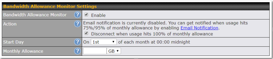
| Bandwidth Allowance Monitor | Check the box Enable to enable bandwidth usage monitoring on this WAN connection for each billing cycle. When this option is not enabled, bandwidth usage of each month is still being tracked but no action will be taken. |
| Action | If email notification is enabled, you will be notified by email when usage hits 75% and 95% of the monthly allowance. If Disconnect when usage hits 100% of monthly allowance is checked, this WAN connection will be disconnected automatically when the usage hits the monthly allowance. It will not resume connection unless this option has been turned off or the usage has been reset when a new billing cycle starts. |
| Start Day | This option allows you to define which day of the month each billing cycle begins. |
| Monthly Allowance | This field is for defining the maximum bandwidth usage allowed for the WAN connection each month. |
| RemoteSIM / FusionSIM / SpeedFusion Connect 5G/LTE | Move scroll bar below to show and adjust those SIM settings. |
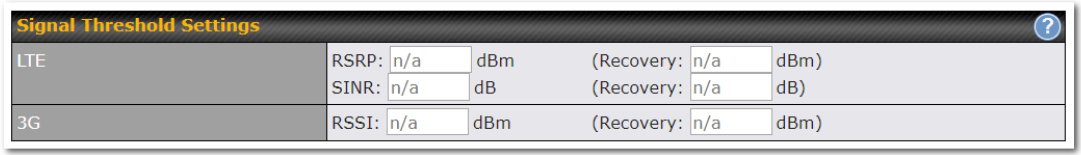
Signal Threshold Settings#
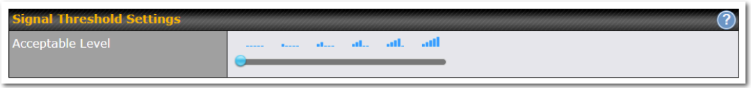
If signal threshold is defined, this connection will be treated as down when a weaker than threshold signal is determined.
The following values are used by the threshold scale:
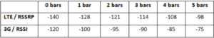
To define the threshold manually using specific signal strength values, please click on the question Mark and the following field will be visible.
WAN Connection Settings (USB)#
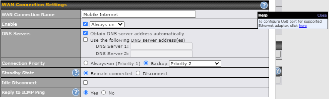
| WAN Connection Settings | |
| WAN Connection Name | Indicate a name you wish to give this WAN connection |
| Enable | This setting enables the WAN connection. If schedules have been defined, you will be able to select a schedule to apply to the connection. |
| DNS Server | Each ISP may provide a set of DNS servers for DNS lookups. This setting specifies the
DNS (Domain Name System) servers to be used when a DNS lookup is routed through this connection. Selecting Obtain DNS server address automatically results in the DNS servers assigned by the WAN DHCP server being used for outbound DNS lookups over the connection. (The DNS servers are obtained along with the WAN IP address assigned by the DHCP server.) When Use the following DNS server address(es) is selected, you may enter custom DNS server addresses for this WAN connection into the DNS server 1 and DNS server 2 fields. |
| Connection Priority | This option allows you to configure the WAN connection whether for normal daily usage or as a backup connection only.
If Always-on is chosen, the WAN connection will be kept on continuously, regardless of the priority of other WAN connections. If Backup is chosen, the WAN connection will depend on other WAN connections. It will not be used when one or more higher priority dependent WAN connections are connected. |
| Standby State | This option allows you to choose whether to remain the connection connected or disconnect it when this WAN connection is no longer in the highest priority and has entered the standby state. |
| Idle Disconnect | If this is checked, the connection will disconnect when idle after the configured Time value. This option is disabled by default. |
| Reply to ICMP Ping | If the checkbox is unticked, this option is disabled and the system will not reply to any ICMP ping echo requests to the WAN IP addresses of this WAN connection.
Default: ticked (Yes) |
By default, the USB port is “USB Modem” mode. If you need to use it to connect to USB Ethernet Adapter, you need to change it to “USB Ethernet” mode, by enabling the hidden feature ![]() . Once this feature is enabled, the interface will behave as normal Ethernet WAN. The options that are the same as the ethernet WAN connection configuration are shown in the Ethernet WAN section.
. Once this feature is enabled, the interface will behave as normal Ethernet WAN. The options that are the same as the ethernet WAN connection configuration are shown in the Ethernet WAN section.
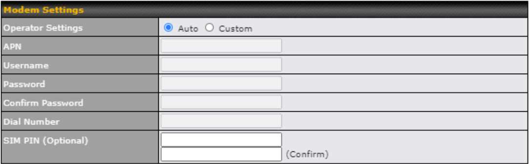
| ModemSettings | |
| Operator Settings | This setting allows you to configure the APN settings of your connection. If Auto is selected, the mobile operator should be detected automatically. The connected device will be configured and connection will be made automatically. If there is any difficulty in making connections, you may select Custom to enter your carrier’s APN, Login, Password, and Dial Number settings manually. The correct values can be obtained from your carrier. The default and recommended setting is Auto. |
| APN / Login / Password / SIM PIN | When Auto is selected, the information in these fields will be filled automatically. Select Custom to customize these parameters. The parameter values are determined by and can be obtained from the ISP. |
WAN Connection Settings (Virtual WAN on VLAN)#
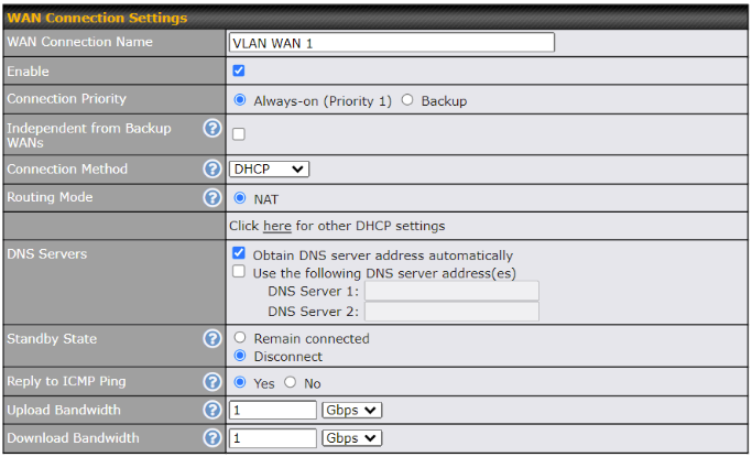
| WAN Connection Settings | |
| WAN Connection Name | Indicate a name you wish to give this WAN connection |
| Enable | This setting enables the WAN connection. If schedules have been defined, you will be able to select a schedule to apply to the connection. |
| Connection Priority | This option allows you to configure the WAN connection whether for normal daily usage or as a backup connection only.
If Always-on is chosen, the WAN connection will be kept on continuously, regardless of the priority of other WAN connections. If Backup is chosen, the WAN connection will depend on other WAN connections. It will not be used when one or more higher priority dependent WAN connections are connected. |
| Independent from Backup WANs | If this is checked, the connection will be working independent from other Backup WAN connections. Those in Backup Priority will ignore the status of this WAN connection, and will be used when none of the other higher priority connections are available. |
| Connection Method | This option allows you to select the connection method for this WAN connection. The available option are DHCP and Static IP. |
| Routing Mode | This field shows that NAT (network address translation) will be applied to the traffic routed over this WAN connection. IP Forwarding is available when you click the link in the help |
| DNS Server | Each ISP may provide a set of DNS servers for DNS lookups. This setting specifies the
DNS (Domain Name System) servers to be used when a DNS lookup is routed through this connection. Selecting Obtain DNS server address automatically results in the DNS servers assigned by the WAN DHCP server being used for outbound DNS lookups over the connection. (The DNS servers are obtained along with the WAN IP address assigned by the DHCP server.) When Use the following DNS server address(es) is selected, you may enter custom DNS server addresses for this WAN connection into the DNS server 1 and DNS server 2 fields. |
| Standby State | This option allows you to choose whether to remain the connection connected or disconnect it when this WAN connection is no longer in the highest priority and has entered the standby state. |
| Reply to ICMP Ping | If the checkbox is unticked, this option is disabled and the system will not reply to any ICMP ping echo requests to the WAN IP addresses of this WAN connection.
Default: ticked (Yes) |
| Upload Bandwidth | This field refers to the maximum upload speed.
This value is referenced when default weight is chosen for outbound traffic and traffic prioritization. A correct value can result in effective traffic prioritization and efficient use of upstream bandwidth. |
| Download Bandwidth | This field refers to the maximum download speed.
Default weight control for outbound traffic will be adjusted according to this value. |
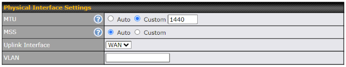
| Physical Interface Settings | |
| MTU | This field is for specifying the Maximum Transmission Unit value of the WAN connection. An excessive MTU value can cause file downloads stall shortly after connected. You may consult your ISP for the connection’s MTU value. Default value is 1440. |
| MSS | This field is for specifying the Maximum Segment Size of the WAN connection.
When Auto is selected, MSS will be depended on the MTU value. When Custom is selected, you may enter a value for MSS. This value will be announced to remote TCP servers for maximum data that it can receive during the establishment of TCP connections. Some Internet servers are unable to listen to MTU setting if ICMP is filtered by firewall between the connections. Normally, MSS equals to MTU minus 40. You are recommended to reduce the MSS only if changing of the MTU value cannot effectively inform some remote servers to size down data size. Default: Auto |
| Uplink Interface | This field is for selecting the WAN / LAN as the uplink interface of the Virtual WAN on VLAN connection. |
| VLAN | Enter the correct VLAN ID for the Virtual WAN on VLAN. |
WAN Connection Settings (OpenVPN)#
OpenVPN WAN is a standalone “WAN” which will appear in both your router and your InControl2 dashboards. You will be able to configure the priority of the physical WANs to connect to the OpenVPN server (similar to IPsec’s “WAN Connection Priority”). You can also customize OpenVPN’s outbound policy, firewall, etc.
* OpenVPN WAN license is required. Click on the below link for more details.
https://forum.peplink.com/t/introducing-the-openvpn-wan-license-partner-discussion/30291

| WAN Connection Settings | |
| WAN Connection Name | Enter a name to represent this WAN connection. |
| Enable | This setting enables the WAN connection. If schedules have been defined, you will be able to select a schedule to apply to the connection. |
| Connection Method | OpenVPN. |
| Routing Mode | This field shows that NAT (network address translation) will be applied to the traffic routed over this WAN connection. IP Forwarding is available when you click the link in the help |
| OpenVPN Profile | Upload the OpenVPN profile (.ovpn) from the OpenVPN server. |
| Login Credential (Optional) | This field is optional to key in the respective username and password to connect to OpenVPN server if needed. |
| DNS Servers | Each ISP may provide a set of DNS servers for DNS lookups. This setting specifies the
DNS (Domain Name System) servers to be used when a DNS lookup is routed through this connection. Selecting Obtain DNS server address automatically results in the DNS servers assigned by the WAN DHCP server being used for outbound DNS lookups over the connection. (The DNS servers are obtained along with the WAN IP address assigned by the DHCP server.) When the following DNS server address(es) is selected, you may enter custom DNS server addresses for this WAN connection into the DNS server 1 and DNS server 2 fields. |
| Connection Priority | This option allows you to configure the WAN connection whether for normal daily usage or as a backup connection only.
If Always-on is chosen, the WAN connection will be kept on continuously, regardless of the priority of other WAN connections. If Backup is chosen, the WAN connection will depend on other WAN connections. It will not be used when one or more higher priority dependent WAN connections are connected. |
| Standby State | This option allows you to choose whether to remain connected when this WAN connection is no longer in the highest priority and has entered the standby state. When Remain connected is chosen, upon bringing up this WAN connection to active, it will be immediately available for use.
If this WAN connection is charged by connection time, you may want to set this option to Disconnect so that connection will be made only when needed. SpeedFusion VPN may use connected standby WAN for failover if link failure detected on the higher priority WAN, you can set this option to Disconnect to avoid data passing through. |
| Reply to ICMP PING | If the checkbox is unticked, this option is disabled and the system will not reply to any ICMP ping echo requests to the WAN IP addresses of this WAN connection.
Default: ticked (Yes) |
| Upload Bandwidth | This field refers to the maximum upload speed.
This value is referenced when default weight is chosen for outbound traffic and traffic prioritization. A correct value can result in effective traffic prioritization and efficient use of upstream bandwidth. |
| Download Bandwidth | This field refers to the maximum download speed.
Default weight control for outbound traffic will be adjusted according to this value. |
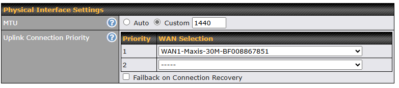
| Physical Interface Settings (OpenVPN) | |
| MTU | This field is for specifying the Maximum Transmission Unit value of the WAN connection. An excessive MTU value can cause file downloads stall shortly after connected. You may consult your ISP for the connection’s MTU value. Default value is 1440. |
| Uplink Connection Priority | Specify the order of WAN connections to be used to establish this OpenVPN connection. The healthy WAN with highest priority will be used. When Failback on Connection Recovery is enabled, once a higher priority WAN is recovered, OpenVPN connection will be disconnected and use that WAN to establish the connection again. |
Health Check Settings#
To ensure traffic is routed to healthy WAN connections only, the Peplink Balance can periodically check the health of each WAN connection.
Health Check settings for each WAN connection can be independently configured via Network > Interfaces > WAN > *Connection name* > Health Check Settings.
Enable Health Check by selecting PING, DNS Lookup, or HTTP from the Health Check Method drop-down menu.
| Health Check Settings | |
| Method | This setting specifies the health check method for the WAN connection. This value can be configured as Disabled, PING, DNS Lookup, or HTTP. The default method is DNS Lookup. For mobile Internet connections, the value of Method can be configured as Disabled or SmartCheck. |
| Health Check Disabled | |

When Disabled is chosen in the Method field, the WAN connection will always be considered as up. The connection will NOT be treated as down in the event of IP routing errors. |
|
| Health Check Method: PING | |
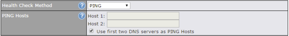
ICMP ping packets will be issued to test the connectivity with a configurable target IP address or hostname. A WAN connection is considered as up if ping responses are received from either one or both of the ping hosts. |
|
| PING Hosts | This setting specifies IP addresses or hostnames with which connectivity is to be tested via ICMP ping. If Use first two DNS servers as Ping Hosts is checked, the target ping host will be the first DNS server for the corresponding WAN connection. Reliable ping hosts with a high uptime should be considered. By default, the first two DNS servers of the WAN connection are used as the ping hosts. |
| Health Check Method: DNS Lookup | |
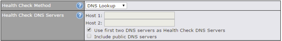
DNS lookups will be issued to test connectivity with target DNS servers. The connection will be treated as up if DNS responses are received from one or both of the servers, regardless of whether the result was positive or negative. |
|
| Health Check DNS Servers | This field allows you to specify two DNS hosts’ IP addresses with which connectivity is to be tested via DNS Lookup.
If Use first two DNS servers as Health Check DNS Servers is checked, the first two DNS servers will be the DNS lookup targets for checking a connection’s health. If the box is not checked, Host 1 must be filled, while a value for Host 2 is optional. If Include public DNS servers is selected and no response is received from all specified DNS servers, DNS lookups will also be issued to some public DNS servers. A WAN connection will be treated as down only if there is also no response received from the public DNS servers. Connections will be considered as up if DNS responses are received from any one of the health check DNS servers, regardless of a positive or negative result. By default, the first two DNS servers of the WAN connection are used as the health check DNS servers. |
| Health Check Method: HTTP | |
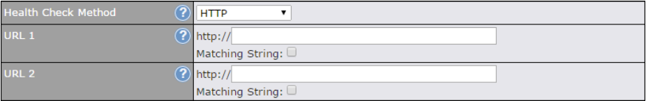 HTTP connections will be issued to test connectivity with configurable URLs and strings to match. |
|
| URL1 | WAN Settings>WAN Edit>Health Check Settings>URL1
HTTP request will be sent according to the specified URL. Health check result is determined based on the HTTP response status code. Status code 2xx, 301 and 302 are classified as success. If Matching String is provided, health check will be determined as success only when the HTTP response content contains the specified string. |
| URL 2 | WAN Settings>WAN Edit>Health Check Settings>URL2
If URL2 is also provided, a health check will pass if either one of the tests passed. |
| Other Health Check Settings | |
 |
|
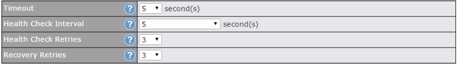
| Timeout | This setting specifies the timeout in seconds for ping/DNS lookup requests. The default timeout is 5 seconds. |
| Health Check Interval | This setting specifies the time interval in seconds between ping or DNS lookup requests. The default health check interval is 5 seconds. |
| Health Check Retries | This setting specifies the number of consecutive ping/DNS lookup timeouts after which the Peplink Balance will treat the corresponding WAN connection as down. Default health retries is set to 3. Using the default Health Retries setting of 3, the corresponding WAN connection will be treated as down after three consecutive timeouts. |
| Recovery Retries | This setting specifies the number of consecutive successful ping/DNS lookup responses that must be received before the Peplink Balance treats a previously down WAN connection as up again. By default, Recover Retries is set to 3. Using the default setting, a WAN connection that is treated as down will be considered as up again upon receiving three consecutive successful ping/DNS lookup responses. |
| Note |
| If a WAN connection goes down, all of the WAN connections not set with a Connection Type of Always-on will also be brought up until any one of higher priority WAN connections is up and found to be healthy. This design could increase overall network availability.
For example, if WAN1, WAN2, and WAN3 have connection types of Always-on, Backup Priority Group 1, and Backup Priority Group 2, respectively, when WAN1 goes down, WAN2 and WAN3 will try to connect. If WAN3 is connected first, WAN2 will still be kept connecting. If WAN2 is connected, WAN3 will disconnect or stop connecting. |
| Automatic Public DNS Server Check on DNS Test Failure |
| When the health check method is set to DNS Lookup and checks fail, the Balance will automatically perform DNS lookups on some public DNS servers. If the tests are successful, the WAN may not be down, but rather the target DNS server malfunctioned. You will see the following warning message on the main page:
|

Physical Interface Settings (Common)#
The remaining WAN-related settings are common to both Ethernet and cellular WAN
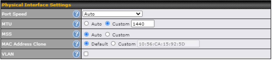
| Physical Interface Settings | |
| Speed | This is the port speed of the WAN connection. It should be set to the same speed as the connected device in case of any port negotiation problems.
When a static speed is set, you may choose whether to advertise its speed to the peer device or not. Advertise Speed is selected by default. You can choose not to advertise the port speed if the port has difficulty in negotiating with the peer device. Default: Auto |
| MTU | This field is for specifying the Maximum Transmission Unit value of the WAN connection. An excessive MTU value can cause file downloads stall shortly after connected. You may consult your ISP for the connection’s MTU value. Default value is 1440. |
| MSS | This field is for specifying the Maximum Segment Size of the WAN connection.
When Auto is selected, MSS will be depended on the MTU value. When Custom is selected, you may enter a value for MSS. This value will be announced to remote TCP servers for maximum data that it can receive during the establishment of TCP connections. Some Internet servers are unable to listen to MTU setting if ICMP is filtered by firewall between the connections. Normally, MSS equals to MTU minus 40. You are recommended to reduce the MSS only if changing of the MTU value cannot effectively inform some remote servers to size down data size. Default: Auto |
| MAC Address Clone | Some service providers (e.g. cable network) identify the client’s MAC address and require client to always use the same MAC address to connect to the network. If it is the case, you may change the WAN interface’s MAC address to the client PC’s one by entering the PC’s MAC address to this field. If you are not sure, click the Default button to restore to the default value. |
| VLAN | Check the box to assign a VLAN to the interface. |
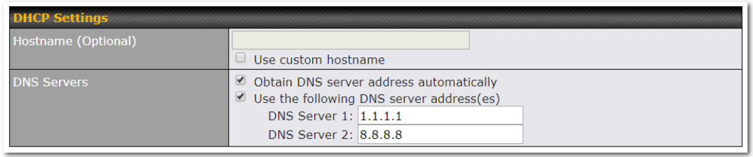
| DHCP Settings | |
| Hostname (Optional) |
If your service provider’s DHCP server requires you to supply a hostname value upon
acquiring an IP address, you may enter the value here. If your service provider does not provide you with a hostname, you can safely bypass this option. |
| DNS Servers | Each ISP may provide a set of DNS servers for DNS lookups. This setting specifies the
DNS (Domain Name System) servers to be used when a DNS lookup is routed through this connection. Selecting Obtain DNS server address automatically results in the DNS servers assigned by the WAN DHCP server being used for outbound DNS lookups over the connection. (The DNS servers are obtained along with the WAN IP address assigned by the DHCP server.) When Use the following DNS server address(es) is selected, you may enter custom DNS server addresses for this WAN connection into the DNS server 1 and DNS server 2 fields. |
Bandwidth Allowance Monitor Settings#
| Bandwidth Allowance Monitor | |
| Action | If Email Notification is enabled, you will be notified by email when usage hits 75% and 95% of the monthly allowance.
If Disconnect when usage hits 100% of monthly allowance is checked, this WAN connection will be disconnected automatically when the usage hits the monthly allowance. It will not resume connection unless this option has been turned off or the usage has been reset when a new billing cycle starts. |
| Start Day | This option allows you to define which day of the month each billing cycle begins. |
| Monthly Allowance | This field is for defining the maximum bandwidth usage allowed for the WAN connection each month. |
| Disclaimer |
| Due to different network protocol overheads and conversions, the amount of data reported by this Peplink device is not representative of actual billable data usage as metered by your network provider. Peplink disclaims any obligation or responsibility for any events arising from the use of the numbers shown here. |
Additional Public IP Settings#
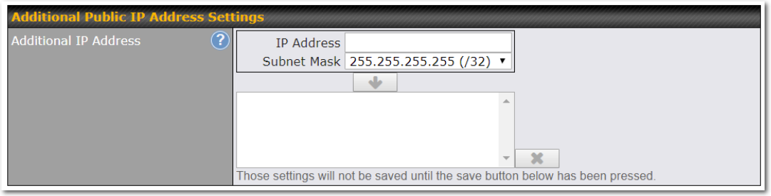
| Additional Public IP Settings | |
| IP Address List | IP Address List represents the list of fixed Internet IP addresses assigned by the ISP in the event that more than one Internet IP address is assigned to this WAN connection. Enter the fixed Internet IP addresses and the corresponding subnet mask, and then click the Down Arrow button to populate IP address entries to the IP Address List. |
Dynamic DNS Settings#
Peplink Balance routers allow registering domain name relationships to dynamic DNS service providers. Through registration with dynamic DNS service provider(s), the default public Internet IP address of each WAN connection can be associated with a hostname. With dynamic DNS service enabled for a WAN connection, you can connect to your WAN’s IP address externally even if its IP address is dynamic. You must register for an account from the listed dynamic DNS service providers before enabling this option.
If the WAN connection’s IP address is a reserved private IP address (i.e., behind a NAT router), the public IP of each WAN will be automatically reported to the DNS service provider.
Either upon a change in IP addresses or every 23 days without link reconnection, the Peplink Balance will connect to the dynamic DNS service provider to update the provider’s IP address records.
The settings for dynamic DNS service provider(s) and the association of hostname(s) are configured via Network>Interfaces>WAN>*Connection name*>Dynamic DNS Settings.
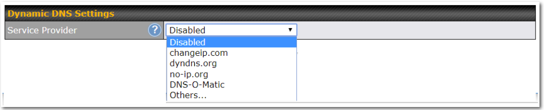
If your desired provider is not listed, you may check with DNS-O-Matic. This service supports updating 30 other dynamic DNS service providers. (Note: Peplink is not affiliated with DNS-O-Matic.)
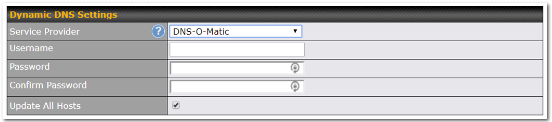
| Dynamic DNS Settings | |
| Service Provider | This setting specifies the dynamic DNS service provider to be used for the WAN. Supported providers are:
support custom Dynamic DNS servers by entering its URL. Works with any service compatible with DynDNS API. Select Disabled to disable this feature. |
| User ID / User / Email | This setting specifies the registered user name for the dynamic DNS service. |
| Password / Pass / TZO Key | This setting specifies the password for the dynamic DNS service. |
| Update All Hosts | Check this box to automatically update all hosts. |
| Hosts / IDs | This setting specifies a list of hostnames or domains to be associated with the public Internet IP address of the WAN connection. |
| Important Note |
| In order to use dynamic DNS services, appropriate hostname registration(s), as well as a valid account with a supported dynamic DNS service provider, are required.
A dynamic DNS update is performed whenever a WAN’s IP address is changed, such as when an IP is changed after a DHCP IP refresh or reconnection. Due to dynamic DNS service providers’ policies, a dynamic DNS host expires automatically when the host record has not been not updated for a long time. Therefore, the Peplink Balance performs an update every 23 days, even if a WAN’s IP address did not change. |
LAN#
Network Settings#
LAN interface settings are located at Network>LAN>Network Settings. Navigating to that page will show the following dashboard:
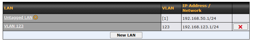
This represents the LAN interfaces that are active on your router (including VLAN). A gray “X” means that the VLAN is used in other settings and cannot be deleted. You can find which settings are using the VLAN by hovering over the gray “X”.
Alternatively, a red “X” means that there are no settings using the VLAN. You can delete that VLAN by clicking the red “X”
Note: Default VLAN 1 is used for untagged LAN. Unused VLAN will be assigned if user has configured VLAN 1 for some other LAN network in previous firmware version.
Clicking on any of the existing LAN interfaces (or creating a new one) will show the following :

| IP Settings | |
| IP Address | The IP address and subnet mask of the Pepwave router on the LAN. |
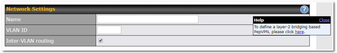
| Network Settings | |
| Name | Enter a name for the LAN. |
| VLAN ID | Enter a number for your VLAN. |
| Inter-VLAN routing | Check this box to enable routing between virtual LANs. |
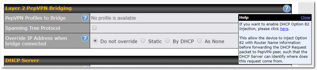
| Layer 2 PepVPN Bridging | |
| PepVPN Profiles to Bridge | The remote network of the selected PepVPN profiles will be bridged with this local LAN, creating a Layer 2 PepVPN, they will be connected and operate like a single LAN, and any broadcast or multicast packets will be sent over the VPN. |
| Remote Network Isolation | Enable this option if you want to block network traffic between the remote networks, this will not affect the connectivity between them and this local LAN. |
| Spanning Tree Protocol | Click the box will enable STP for this layer 2 profile bridge. |
| Override IP Address when bridge connected | Select “Do not override” if the LAN IP address and local DHCP server should remain unchanged after the Layer 2 PepVPN is up.
If you choose to override IP address when the VPN is connected, the device will not act as a router, and most Layer 3 routing functions will cease to work. |
| DHCP Option 82 | Click on the question Mark if you want to enable DHCP Option 82.
This allows the device to inject Option 82 with Router Name information before forwarding the DHCP Request packet to a PepVPN peer, such that the DHCP Server can identify where the request originates from. |

| DHCP Server Settings | |
| DHCP Server | When this setting is enabled, the DHCP server automatically assigns an IP address to each computer that is connected via LAN and configured to obtain an IP address via DHCP. The Pepwave router’s DHCP server can prevent IP address collision on the LAN. |
| DHCP Server Logging | Enable logging of DHCP events in the eventlog by selecting the checkbox. |
| IP Range & Subnet Mask | These settings allocate a range of IP addresses that will be assigned to LAN computers by the Pepwave router’s DHCP server. |
| Lease Time | This setting specifies the length of time throughout which an IP address of a DHCP client remains valid. Upon expiration of the lease time, the assigned IP address will no longer be valid and renewal of the IP address assignment will be required. |
| DNS Servers | This option allows you to input the DNS server addresses to be offered to DHCP clients. If Assign DNS server automatically is selected, the Pepwave router’s built-in DNS server address (i.e., LAN IP address) will be offered. |
| WINS Servers | This option allows you to optionally specify a Windows Internet Name Service (WINS) server. You may choose to use the built-in WINS server or external WINS servers.
When this unit is connected using SpeedFusionTM, other VPN peers can share this unit’s built-in WINS server by entering this unit’s LAN IP address in their DHCP WINS Server setting. Afterward, all PC clients in the VPN can resolve the NetBIOS names of other clients in remote peers. If you have enabled this option, a list of WINS clients will be displayed at Status>WINS Clients. |
| BOOTP | Check this box to enable BOOTP on older networks that still require it. |
| Extended DHCP Option | In addition to standard DHCP options (e.g., DNS server address, gateway address, subnet mask), you can specify the value of additional extended DHCP options, as defined in RFC 2132. With these extended options enabled, you can pass additional configuration information to LAN hosts.
To define an extended DHCP option, click the Add button, choose the option to define and enter its value. For values that are in IP address list format, you can enter one IP address per line in the provided text area input control. Each option can be defined once only. |
| DHCP Exclusion Range | To reserve a range of IP addresses from the DHCP pool, users may exclude a smaller range of IP addresses to avoid IP release behavior.
Note: The start IP should be lower than the end IP, and both the start and end IPs should be within the range of the DHCP pool. |
| DHCP Reservation | This setting reserves the assignment of fixed IP addresses for a list of computers on the LAN. The computers to be assigned fixed IP addresses on the LAN are identified by their MAC addresses. The fixed IP address assignment is displayed as a cross-reference list between the computers’ names, MAC addresses, and fixed IP addresses.
Name (an optional field) allows you to specify a name to represent the device. MAC addresses should be in the format of 00:AA:BB:CC:DD:EE. Press |
| User Account IP Address Reservation | This setting reserves the fixed IP addresses assignment for the list of Remote User Access accounts. |
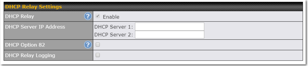
| DHCP Relay Settings | |
| DHCP Relay | Enter the address of the DHCP server here. DHCP requests will be relayed to it. |
| DHCP Server IP Address | DHCP requests from the LAN are relayed to the entered DHCP server.
For active-passive DHCP server configurations, enter active and passive DHCP server IPs into the DHCP Server 1 and DHCP Server 2 fields. |
| DHCP Option 82 | This feature includes device information as relay agent for the attached client when forwarding DHCP requests from a DHCP client to a DHCP server. Device MAC address and network name are embedded to circuit ID and Remote ID in option 82. |
| DHCP Relay Logging | Check this box to log DHCP relay activity. |
Network Settings (Common Settings)#
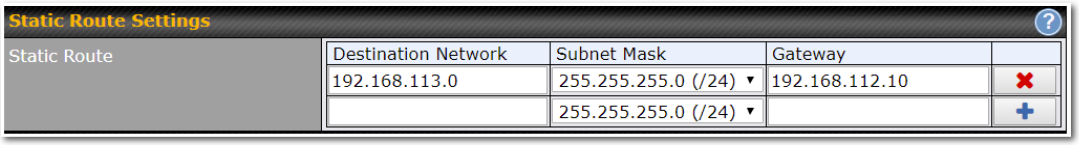
| Static Route Settings | |
| Static Route | This table is for defining static routing rules for the LAN segment. A static route consists of the network address, subnet mask, and gateway address. The address and subnet mask values are in w.x.y.z format.
The local LAN subnet and subnets behind the LAN will be advertised to the VPN. Remote routes sent over the VPN will also be accepted. Any VPN member will be able to route to the local subnet. Click Entries in this list will allow traffic to route to a different subnet that is connected to the LAN interface. Any traffic destined for a network/mask pair will be directed to the corresponding gateway instead of routed through WANs. |
A – Advanced feature, please click the ![]() button on the top right hand corner of the Static Route session to activate and configure Virtual Network Mapping to resolve network address conflict with remote peers.
button on the top right hand corner of the Static Route session to activate and configure Virtual Network Mapping to resolve network address conflict with remote peers.
In case of a network address conflict with remote peers (i.e. PepVPN / IPsec VPN / IP Forwarding WAN are considered as remote connections), you can define Virtual Network Mapping to resolve it.
Note: OSPF & RIPv2 settings should be updated as well to avoid advertising conflicted networks.
For further details on virtual network mapping watch this video: https://youtu.be/C1FMdZCn3Z8
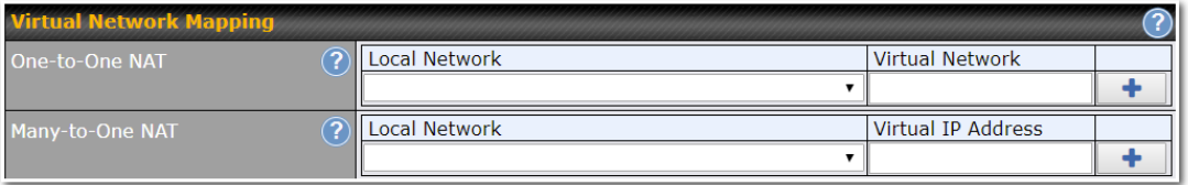
| Virtual Network Mapping | |
| One-to-One NAT | Every IP Address in the Local Network has a corresponding unique Virtual IP Address for NAT. Traffic originating from the Local Network to remote connections will be SNAT’ed and behave like coming from the defined Virtual Network. While traffic initiated by remote peers to the Virtual Network will be DNAT’ed accordingly. |
| Many-to-One NAT | The subnet range defined in Local Network will be mapped to a single Virtual IP Address for NAT. Traffic can only be initiated from local to remote, and these traffic will be NAT’ed and behaves like coming from the same Virtual IP Address. |

| WINS Server Settings | |
| Enable | Check the box to enable the WINS Server. A list of WINS clients will be displayed at Status>WINS Clients. |
Enter any needed DNS proxy settings. Once all settings have been entered, click Save to store your changes.
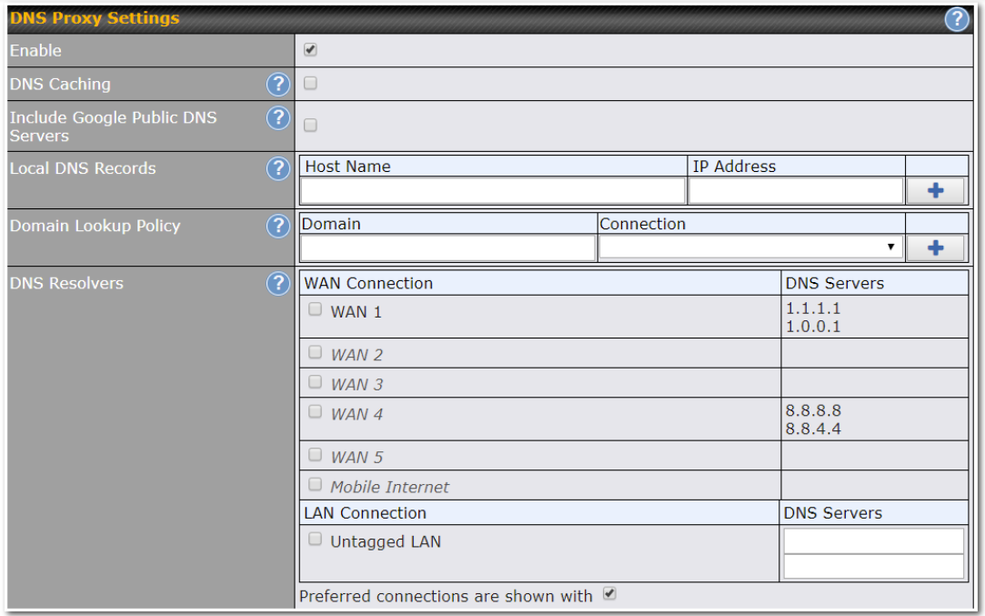
| DNS Proxy Settings | |
| Enable | To enable the DNS proxy feature, check this box, and then set up the feature at Network>LAN>DNS Proxy Settings.
A DNS proxy server can be enabled to serve DNS requests originating from LAN/PPTP/SpeedFusionTM peers. Requests are forwarded to the DNS servers/resolvers defined for each WAN connection. |
| DNS Caching | This field is to enable DNS caching on the built-in DNS proxy server. When the option is enabled, queried DNS replies will be cached until the records’ TTL has been reached. This feature can improve DNS response time by storing all received DNS results for faster DNS lookup. However, it cannot return the most updated result for frequently updated DNS records. By default, DNS Caching is disabled. |
| Include Google Public DNS Servers | When this option is enabled, the DNS proxy server will forward DNS requests to Google’s public DNS servers, in addition to the DNS servers defined in each WAN. This could increase the DNS service’s availability. This setting is disabled by default. |
| Local DNS Records | This table is for defining custom local DNS records. A static local DNS record consists of a host name and IP address. When looking up the host name from the LAN to LAN IP of the Peplink Balance, the corresponding IP address will be returned. To display the option to set TTL manually, click |
| Domain Lookup Policy | DNS proxy will look up the domain names defined here using only the specified connections. |
| DNS Resolvers^ | Check the box to enable the WINS server. A list of WINS clients will be displayed at Network>LAN>DNS Proxy Settings>DNS Resolvers.
This field specifies which DNS resolvers will receive forwarded DNS requests. If no WAN/VPN/LAN DNS resolver is selected, all of the WAN’s DNS resolvers will be selected. |
^ Advanced feature, please click the ![]() button on the top right-hand corner to activate.
button on the top right-hand corner to activate.
Finally, if needed, configure your Bonjour forwarding settings. Once all settings have been entered, click Save to store your changes.
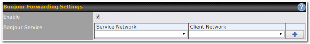
| Bonjour Forwarding Settings | |
| Enable | Check this box to turn on Bonjour forwarding. |
| Bonjour Service | Choose Service and Client networks from the drop-down menus, and then click Bonjour Forwarding is supported on All Balance models, MAX 700, HD2, HD4 |
Drop-In Mode#
Drop-in mode (or transparent bridging mode) eases the installation of the Peplink Balance on a live network between the firewall and router, such that changes to the settings of existing equipment are not required.
The following diagram illustrates drop-in mode setup:

Enable drop-in mode using the Setup Wizard. After enabling this feature and selecting the WAN for drop-in mode, various settings, including the WAN’s connection method and IP address, will be automatically updated.
When drop-in mode is enabled, the LAN and the WAN for drop-in mode ports will be bridged. Traffic between the LAN hosts and WAN router will be forwarded between the devices. In this case, the hosts on both sides will not notice any IP or MAC address changes.
After successfully setting up the Peplink Balance as part of the network using drop-in mode, it will, depending on model, support one or more WAN connections. Some MediaFast units also support multiple WAN connections after activating drop-in mode, though a SpeedFusion license may be required to activate more than one WAN port.
Please note the Drop-In Mode is mutually exclusive with VLAN.
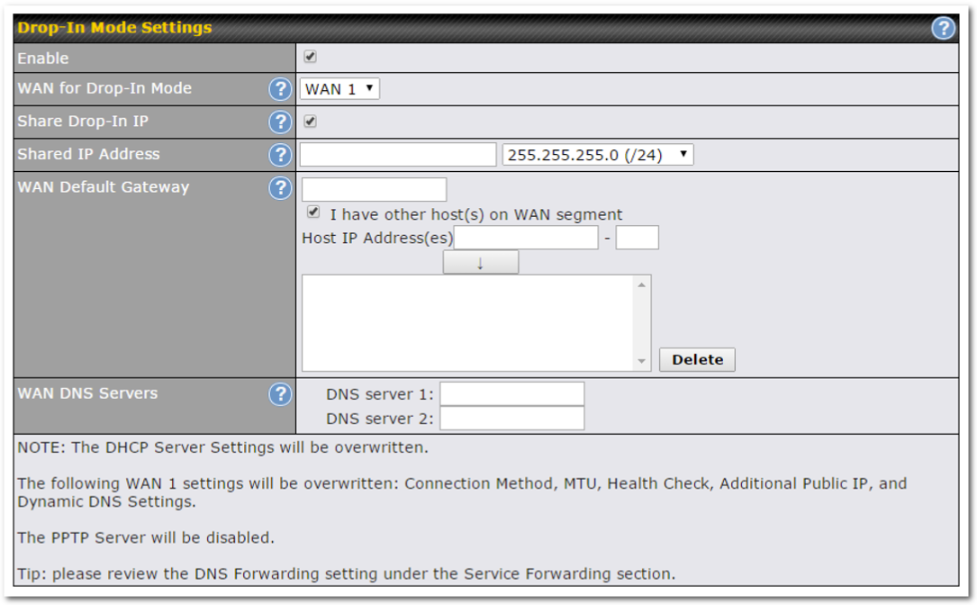
| Drop-in Mode Settings | |
| Enable | Drop-in mode eases the installation of the Peplink Balance on a live network between the existing firewall and router, such that no configuration changes are required on existing equipment. Check the box to enable the drop-in mode feature.
Please refer to Section 12, Drop-in Mode for details. |
| WAN for Drop-In Mode | Select the WAN port to be used for drop-in mode. If WAN 1 with LAN Bypass is selected, the high availability feature will be disabled automatically. |
| Shared Drop-In IPA | When this option is enabled, the passthrough IP address will be used to connect to WAN hosts (email notification, remote syslog, etc.). The Balance will listen for this IP address when WAN hosts access services provided by the Balance (web admin access from the WAN, DNS server requests, etc.).
To connect to hosts on the LAN (email notification, remote syslog, etc.), the default gateway address will be used. The Balance will listen for this IP address when LAN hosts access services provided by the Balance (web admin access from the WAN, DNS proxy, etc.). |
| Shared IP AddressA | Access to this IP address will be passed through to the LAN port if this device is not serving the service being accessed. The shared IP address will be used in connecting to hosts on the WAN (e.g., email notification, remote syslog, etc.) The device will also listen on the IP address when hosts on the WAN access services served on this device (e.g., web admin accesses from WAN, DNS server, etc.) |
| WAN Default Gateway | Enter the WAN router’s IP address in this field. If there are more hosts in addition to the router on the WAN segment, click the |
| WAN DNS Servers | Enter the selected WAN’s corresponding DNS server IP addresses. |
A – Advanced feature, please click the ![]() button on the top right-hand corner to activate.
button on the top right-hand corner to activate.
Port Settings#
To configure port settings, navigate to Network > Port Settings

On this screen, you can enable specific ports, as well as determine the speed of the LAN ports, whether each port is a trunk or access port, as well as which VLAN each link belongs to, if any.
Untagged frames received by the port are classified to a VLAN indicated by Port VLAN Identifier (PVID). All frames from the VLAN are untagged on egress.PVID option is only configurable when Port Type is set to “Trunk”.
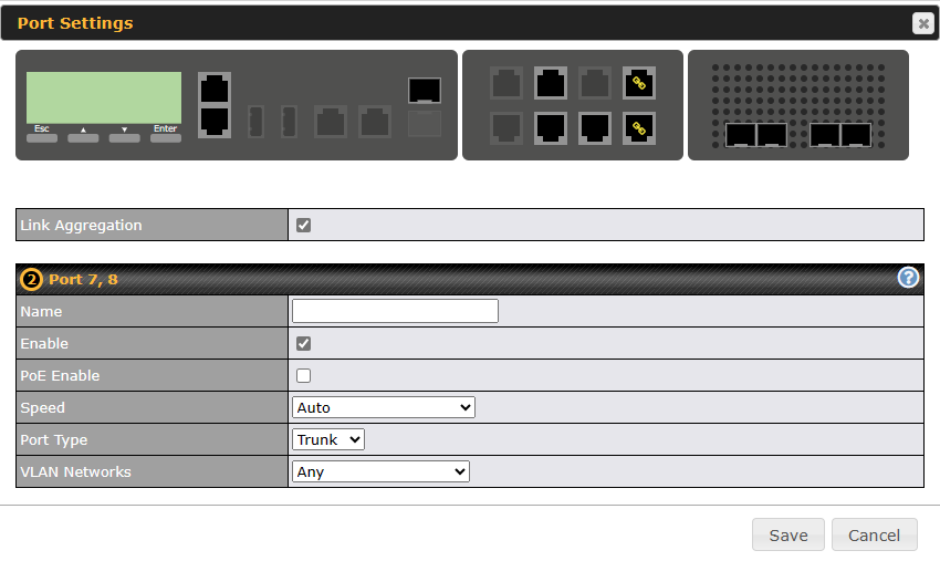
LACP settings#

To configure LACP settings, select multiple ports by clicking the ports. After clicking, a tick will appear on the selected port.
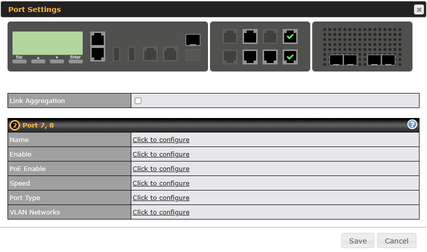
After enabling the ‘Link Aggregation‘ option, the tick icon will change to a chains icon. The settings below will also be available for configuration, if any further actions are needed.
VPN#
SpeedFusion VPN#
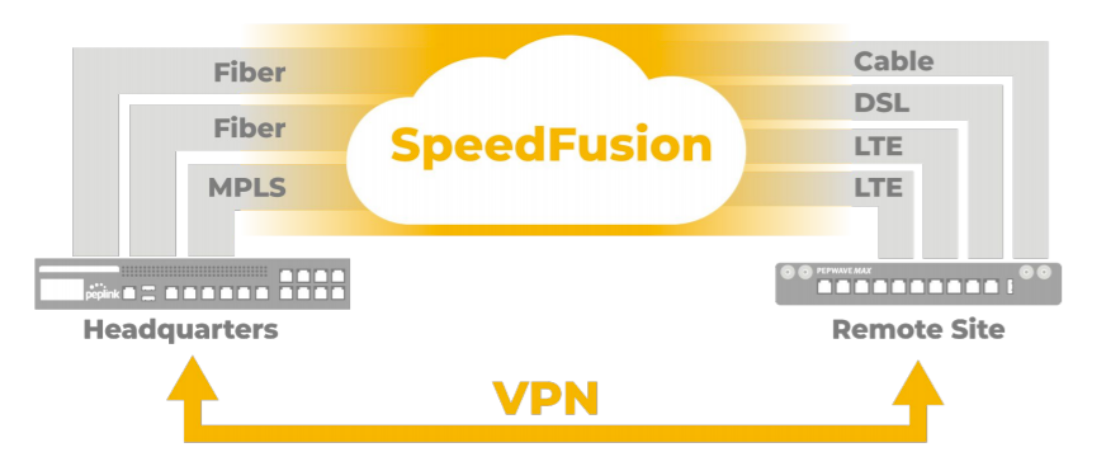
Peplink Balance SpeedFusionTM Bandwidth Bonding is our patented technology that enables our SD-WAN routers to bond multiple Internet connections to increase site-to-site bandwidth and reliability. SpeedFusion securely connects one or more branch offices to your company’s main headquarters or to other branches. The data, voice, and video communications between these locations are kept confidential across the public Internet.
The SpeedFusionTM of the Peplink Balance is specifically designed for multi-WAN environments. With SpeedFusion, in case of failures and network congestion at one or more WANs, other WANs can be used to continue carrying the network traffic. Peplink Balance routers can bond all WAN connections’ bandwidth for routing SpeedFusionTM traffic. Unless all the WAN connections of one site are down, the Peplink Balance can keep the VPN up and running.
Bandwidth bonding is enabled by default.
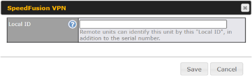
To begin, navigate to Network > VPN > SpeedFusion VPN and enter a Local ID and click save.
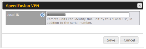
This device will be identified by other SpeedFusion VPN Peers by this local ID. The following menus will appear:
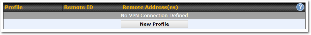
| SpeedFusion VPN Profiles |
| This table displays all defined profiles. Click the New Profile button to create a new profile for making a VPN connection to a remote unit via available WAN connections. Each pair of VPN connection requires its own profile.
The local LAN subnet and subnets behind the LAN (defined under Static Route on the LAN Settings page) will be advertised to the VPN. All VPN members will be able to route to local subnets. |

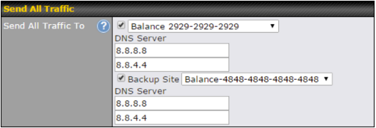
| Send All Traffic To |
| This feature allows you to redirect all traffic to a specified SpeedFusion VPN connection. Click the
|

| SpeedFusion VPN Local ID |
| This feature allows you to change the local ID of a SpeedFusion VPN connection. Click the
|
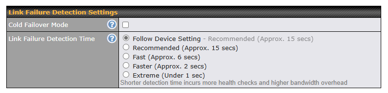
| Link Failure Detection Settings | |
| Cold Failover Mode | Enabling Cold Failover Mode turns off link failure detection for standby WAN-to-WAN links, helping to lower bandwidth consumption. |
| Link Failure Detection Time | The bonded VPN can detect routing failures on the path between two sites over each WAN connection. Failed WAN connections will not be used to route VPN traffic. Health check packets are sent to the remote unit to detect any failure. The more frequently checks are sent, the shorter the detection time, although more bandwidth will be consumed.
When Recommended (default) is selected, a health check packet is sent every five seconds, and the expected detection time is 15 seconds. When Fast is selected, a health check packet is sent every three seconds, and the expected detection time is six seconds. When Faster is selected, a health check packet is sent every second, and the expected detection time is two seconds. When Extreme is selected, a health check packet is sent every 0.1 second, and the expected detection time is less than one second. |
| Important Note |
| Peplink proprietary SpeedFusionTM uses TCP port 32015 and UDP port 4500 for establishing VPN connections. If you have a firewall in front of your Peplink Balance devices, you will need to add firewall rules for these ports and protocols to allow inbound and outbound traffic to pass through the firewall. |
SpeedFusion: Profile Configuration#
Click the New Profile button, or click one of the existing profiles, and the following menus will appear:
A list of defined SpeedFusion connection profiles and a Link Failure Detection Time option will be shown. Click the New Profile button to create a new VPN connection profile for making a VPN connection to a remote Peplink Balance via the available WAN connections. Each profile is for making a VPN connection with one remote Peplink Balance.
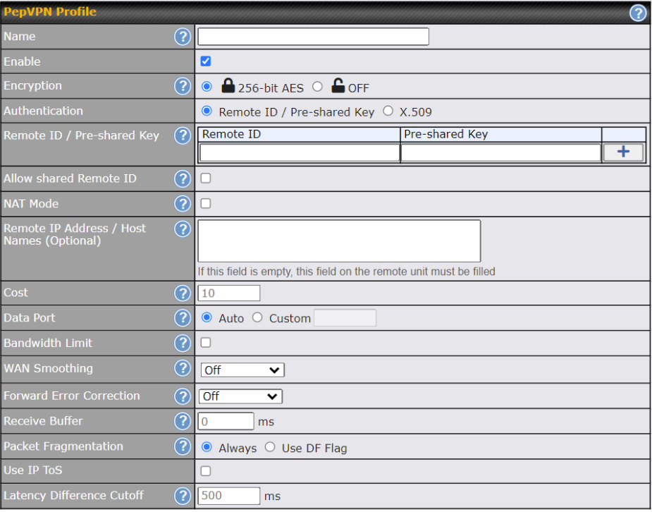
| SpeedFusion VPN Profile | |
| Name | This field is for specifying a name to represent this profile. The name can be any combination of alphanumeric characters (0-9, A-Z, a-z), underscores (_), dashes (-), and/or non-leading/trailing spaces ( ).
Click the |
| Enable | When this box is checked, this VPN connection profile will be enabled. Otherwise, it will be disabled. |
| Encryption | By default, VPN traffic is encrypted with 256-bit AES. If Off is selected on both sides of a VPN connection, no encryption will be applied. |
| Authentication | Select from By Remote ID Only, Preshared Key, or X.509 to specify the method the Peplink Balance will use to authenticate peers. When selecting By Remote ID Only, be sure to enter a unique peer ID number in the Remote ID field. |
| Remote ID /
Pre-shared Key |
This optional field becomes available when Remote ID / Pre-shared Key is selected as the Peplink Balance’s VPN Authentication method, as explained above. Pre-shared Key defines the pre-shared key used for this particular VPN connection. The VPN connection’s session key will be further protected by the pre-shared key. The connection will be up only if the pre-shared keys on each side match. When the peer is running firmware 5.0+, this setting will be ignored.
Enter Remote IDs either by typing out each Remote ID and Pre-shared Key, or by pasting a CSV. If you wish to paste a CSV, click the |
| Remote ID/Remote Certificate | These optional fields become available when X.509 is selected as the Peplink Balance’s VPN authentication method, as explained above. To authenticate VPN connections using X.509 certificates, copy and paste certificate details into these fields. To get more information on a listed X.509 certificate, click the Show Details link below the field. |
| Allow Shared Remote ID | When this option is enabled, the router will allow multiple peers to run using the same remote ID. |
| NAT Mode | Check this box to allow the local DHCP server to assign an IP address to the remote peer. When NAT Mode is enabled, all remote traffic over the VPN will be tagged with the assigned IP address using network address translation. |
| Remote IP Address / Host Names (Optional) | If NAT Mode is not enabled, you can enter a remote peer’s WAN IP address or hostname(s) here. If the remote uses more than one address, enter only one of them here. Multiple hostnames are allowed and can be separated by a space character or carriage return. Dynamic-DNS host names are also accepted.
This field is optional. With this field filled, the Peplink Balance will initiate connection to each of the remote IP addresses until it succeeds in making a connection. If the field is empty, the Peplink Balance will wait for connection from the remote peer. Therefore, at least one of the two VPN peers must specify this value. Otherwise, VPN connections cannot be established. Click the |
| Cost | Define path cost for this profile.
OSPF will determine the best route through the network using the assigned cost. Default: 10 |
| Data Port | This field is used to specify a UDP port number for transporting outgoing VPN data. If Default is selected, UDP port 4500 will be used. Port 32015 will be used if the remote unit uses Firmware prior to version 5.4 or if port 4500 is unavailable. If Custom is selected, enter an outgoing port number from 1 to 65535.
Click the |
| Bandwidth Limit | Define maximum download and upload speed to each individual peer. This functionality requires the peer to use PepVPN version 4.0.0 or above. |
| TCP Ramp Up | For every new TCP connection, Normal WAN Smoothing will be applied for a short period of time to prevent packet loss during TCP Slow Start, which in some conditions will ramp up TCP throughput faster. |
| WAN Smoothing | While using PepVPN, utilize multiple WAN links to reduce the impact of packet loss and get the lowest possible latency at the expense of extra bandwidth consumption. This is suitable for streaming applications where the average bitrate requirement is much lower than the WAN’s available bandwidth.
Off – Disable WAN Smoothing. Normal – The total bandwidth consumption will be at most 2x of the original data traffic. Medium – The total bandwidth consumption will be at most 3x of the original data traffic. High – The total bandwidth consumption depends on the number of connected active tunnels. |
| Forward Error Correction | Forward Error Correction (FEC) can help to recover packet loss by using extra bandwidth to send redundant data packets. Higher FEC level will recover packets on a higher loss rate link.
For more information on FEC and Adaptive FEC, refer to this KB article.
Require peer using PepVPN version 8.0.0 and above. |
| Receive Buffer | Receive Buffer can help to reduce out-of-order packets and jitter, but will introduce extra latency to the tunnel. Default is 0 ms, which disables the buffer, and maximum buffer size is 2000 ms. |
| Packet Fragmentation | If the packet size is larger than the tunnel’s MTU, it will be fragmented inside the tunnel in order to pass through.
Select Always to fragment any packets that are too large to send, or Use DF Flag to only fragment packets with Don’t Fragment bit cleared. This can be useful if your application does Path MTU Discovery, usually sending large packets with DF bit set, if allowing them to go through by fragmentation, the MTU will not be detected correctly. |
| Use IP ToS^ | If Use IP ToS is enabled, the ToS value of the data packets will be copied to the PepVPN header during encapsulation. |
| Latency Difference Cutoff^ | Traffic will be stopped for links that exceed the specified millisecond value with respect to the lowest latency link. (e.g. Lowest latency is 100ms, a value of 500ms means links with latency 600ms or more will not be used) |
^ Advanced feature, please click the ![]() button on the top right-hand corner to activate.
button on the top right-hand corner to activate.
To enable Layer 2 Bridging between PepVPN profiles, navigate to Network>LAN>*LAN Profile Name*
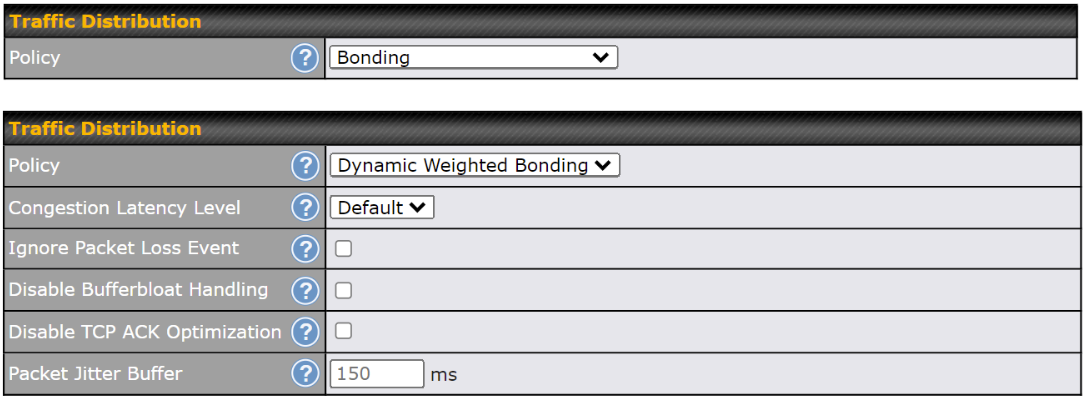
| Traffic Distribution | |
| Policy | This option allows you to select the desired out-bound traffic distribution policy:
By default, Bonding is selected as a traffic distribution policy. |
| Congestion Latency Level | For most WANs, especially on cellular networks, the latency will increase when the link becomes more congested.
Setting the Congestion Latency Level to Low will treat the link as congested more aggressively. Setting it to High will allow the latency to increase more before treating it as congested. |
| Ignore Packet Loss Event | By default, when there is packet loss, it is considered as a congestion event. If this is not the case, select this option to ignore the packet loss event. |
| Disable Bufferbloat Handling | Bufferbloat is a phenomenon on the WAN side when it is congested. The latency can become very high due to buffering on the uplink. By default, the Dynamic Weighted Bonding policy will try its best to mitigate bufferbloat by reducing TCP throughput when the WAN is congested. However, as a side effect, the tunnel might not achieve maximum bandwidth.
Selecting this option will disable the bufferbloat handling mentioned above. |
| Disable TCP ACK Optimization | By default, TCP ACK will be forwarded to remote peers as fast as possible. This will consume more bandwidth, but may help to improve TCP performance as well.
Selecting this option will disable the TCP ACK optimization mentioned above. |
| Packet Jitter Buffer | The default jitter buffer is 150ms, and can be modified from 0ms to 500ms. The jitter buffer may increase the tunnel latency. If you want to keep the latency as low as possible, you can set it to 0ms to disable the buffer.
Note: If the Receive Buffer is set, the Packet Jitter Buffer will be automatically disabled. |
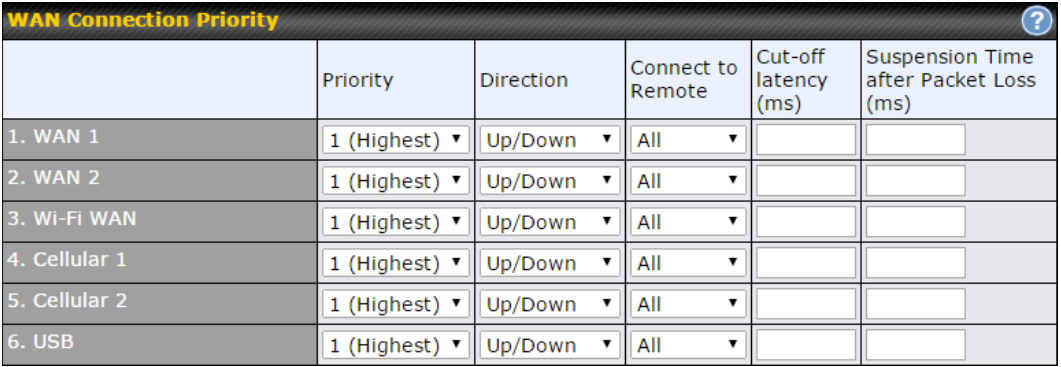
| WAN Connection Priority | |
| WAN Connection Priority | If your device supports it, you can specify the priority of WAN connections to be used for making VPN connections. WAN connections set to OFF will never be used. Only available WAN connections with the highest priority will be used.
To enable asymmetric connections, connection mapping to remote WANs, cut-off latency, and packet loss suspension time, click the |
Peplink also published a whitepaper about Speedfusion which can be downloaded from the following url:
http://download.peplink.com/resources/whitepaper-speedfusion-and-best-practices-2019.pdf
IPsec VPN#
Peplink Balance IPsec VPN functionality securely connects one or more branch offices to your company’s main headquarters or to other branches. Data, voice, and video communications between these locations are kept safe and confidential across the public Internet.
All Peplink products can make multiple IPsec VPN connections with Peplink routers, as well as Cisco and Juniper routers.
Note that all LAN subnets and the subnets behind them must be unique. Otherwise, VPN members will not be able to access each other.
All data can be routed over the VPN with a selection of encryption standards, such as 3DES, AES-128, and AES-256.
To configure, navigate to Network > VPN >IPsec VPN.
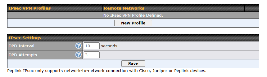
A NAT-Traversal option and list of defined IPsec VPN profiles will be shown.
NAT-Traversal should be enabled if your system is behind a NAT router.
Click the New Profile button to create new IPsec VPN profiles that make VPN connections to remote Peplink Balance, Cisco, or Juniper Routers via available WAN connections. To edit any of the profiles, click on its associated connection name in the leftmost column.
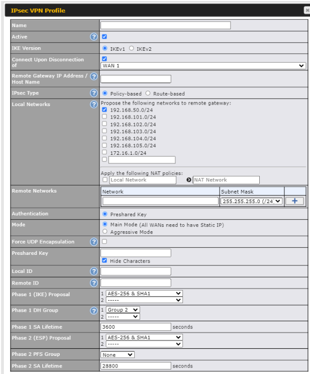
| IPsec VPN Settings | |
| Name | This field is for specifying a local name to represent this connection profile. |
| Active | When this box is checked, this IPsec VPN connection profile will be enabled. Otherwise, it will be disabled. |
| IKE Version | Two versions of the IKE standards are available:
|
| Connect Upon Disconnection of | Check this box and select a WAN to connect to this VPN automatically when the specified WAN is disconnected. To activate this function, click the |
| Remote Gateway IP Address / Host Name | Enter the remote peer’s public IP address. For Aggressive Mode, this is optional. |
| IPsec Type | Policy-based – (default) All the matched traffic as defined in Local Networks and Remote Networks will be routed to this IPsec connection, this cannot be overridden by other routing methods.
Route-based – Outbound Policy rule is required to route traffic to this tunnel and comes with more flexibility to control how to route traffic compared to Policy-based. If you want to modify the traffic selector instead of using the default (0.0.0.0/0). Note: This option is only available for the following models:
|
| Local Networks | Enter the local LAN subnets here. If you have defined static routes, they will be shown here.
Using NAT, you can map a specific local network / IP address to another, and the packets received by remote gateway will appear to be coming from the mapped network / IP address. This allows you to establish IPsec connection to a remote site that has one or more subnets overlapped with local site. Two types of NAT policies can be defined: One-to-One NAT policy: if the defined subnet in Local Network and NAT Network has the same size, for example, policy “192.168.50.0/24 > 172.16.1.0/24” will translate the local IP address 192.168.50.10 to 172.16.1.10 and 192.168.50.20 to 172.16.1.20. This is a bidirectional mapping which means clients in remote site can initiate connection to the local clients using the mapped address too. Many-to-One NAT policy: if the defined NAT Network on the right hand side is an IP address (or having a network prefix /32), for example, policy “192.168.1.0/24 > 172.168.50.1/32” will translate all clients in 192.168.1.0/24 network to 172.168.50.1. This is a unidirectional mapping which means clients in remote site will not be able to initiate a connection to the local clients. |
| Remote Networks | Enter the LAN and subnets that are located at the remote site here. |
| Authentication | To access your VPN, clients will need to authenticate by your choice of methods. Choose between the Preshared Key and X.509 Certificate methods of authentication. |
| Mode | Choose Main Mode if both IPsec peers use static IP addresses. Choose Aggressive Mode if one of the IPsec peers uses dynamic IP addresses. |
| Force UDP Encapsulation | For forced UDP encapsulation regardless of NAT-traversal, tick this checkbox. |
| Pre-shared Key | This defines the peer authentication pre-shared key used to authenticate this VPN connection. The connection will be up only if the pre-shared keys on each side match. |
| Remote Certificate (pem encoded) | Available only when X.509 Certificate is chosen as the Authentication method, this field allows you to paste a valid X.509 certificate. |
| Local ID | In Main Mode, this field can be left blank. In Aggressive Mode, if Remote Gateway IP Address is filled on this end and the peer end, this field can be left blank. Otherwise, this field is typically a U-FQDN. |
| Remote ID | In Main Mode, this field can be left blank. In Aggressive Mode, if Remote Gateway IP Address is filled on this end and the peer end, this field can be left blank. Otherwise, this field is typically a U-FQDN. |
| Phase 1 (IKE) Proposal | In Main Mode, this allows setting up to six encryption standards, in descending order of priority, to be used in initial connection key negotiations. In Aggressive Mode, only one selection is permitted. |
| Phase 1 DH Group | This is the Diffie-Hellman group used within IKE. This allows two parties to establish a shared secret over an insecure communications channel. The larger the group number, the higher the security.
Group 2: 1024-bit is the default value. Group 5: 1536-bit is the alternative option. |
| Phase 1 SA Lifetime | This setting specifies the lifetime limit of this Phase 1 Security Association. By default, it is set at 3600 seconds. |
| Phase 2 (ESP) Proposal | In Main Mode, this allows setting up to six encryption standards, in descending order of priority, to be used for the IP data that is being transferred. In Aggressive Mode, only one selection is permitted. |
| Phase 2 PFS Group | Perfect forward secrecy (PFS) ensures that if a key was compromised, the attacker will be able to access only the data protected by that key.
None – Do not request for PFS when initiating connection. However, since there is no valid reason to refuse PFS, the system will allow the connection to use PFS if requested by the remote peer. This is the default value. Group 2: 1024-bit Diffie-Hellman group. The larger the group number, the higher the security. Group 5: 1536-bit is the third option. |
| Phase 2 SA Lifetime | This setting specifies the lifetime limit of this Phase 2 Security Association. By default, it is set at 28800 seconds. |
IPsec VPN on the Peplink Balance is specially designed for multi-WAN environments. For instance, if a user sets up multiple IPsec profiles for his multi-WAN environment and WAN1 is connected and healthy, IPsec traffic will go through this link. However, should unforeseen problems (e.g.,unplugged cables or ISP problems) cause WAN1 to go down, our IPsec implementation will make use of WAN2 and WAN3 for failover
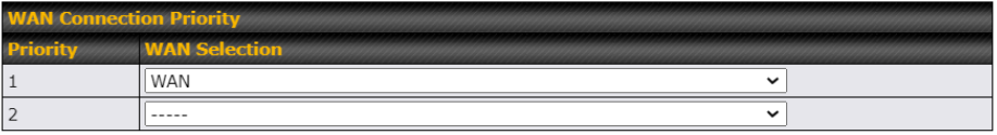
IPsec Status shows the current connection status of each connection profile and is displayed at Status > IPsec VPN.
| IPsec Settings | |
| DPD Interval | Time interval between Dead Peer Detection (DPD) messages (R_U_THERE in IKEv1 or INFORMATIONAL in IKEv2) that check if the peer is still active when no other traffic is present.
Default: 10 seconds (2–30 seconds) |
| DPD Attempts | Total number of DPD messages sent before the peer is considered unreachable.
Default: 3 times (2-10 times) |
GRE Tunnel#
Generic Routing Encapsulation (GRE) is a tunneling protocol that can encapsulate a wide variety of network layer protocols inside virtual point-to-point links over an Internet Protocol network. A GRE tunnel is similar to IPSec or SpeedFusion VPN.
To configure a GRE Tunnel, navigate to Network > VPN > GRE Tunnel.

Click the New Profile button to create new GRE tunnel profiles that establish tunnel connections to remote tunnel endpoints via available WAN connections. To edit the profiles, click on its associated connection name in the leftmost column.
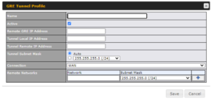
| GRE Tunnel Profile Settings | |
| Name | This field is for specifying a name to represent this GRE Tunnel connection profile. |
| Active | When this box is checked, this GRE Tunnel connection profile will be enabled. Otherwise, it will be disabled. |
| Remote GRE IP Address | This field is for entering the remote GRE’s IP address |
| Tunnel Local IP Address | This field is for specifying the tunnel source IP address. |
| Tunnel Remote IP Address | This field is for specifying the tunnel destination IP address |
| Tunnel Subnet Mask | This field is to select the subnet mask that is to be used for the GRE tunnel. |
| Connection | Select the appropriate WAN connection from the drop-down menu. |
| Remote Networks | Input the LAN and subnets that are located at the remote site here. |
OpenVPN#
OpenVPN is a site to site VPN mode that can encapsulate a wide variety of network layer protocols inside virtual point-to-point links over an Internet Protocol network.
To configure a OpenVPN, navigate to Advanced > OpenVPN and click the New Profile.
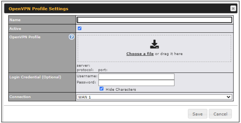
| OpenVPN Profile Settings | |
| Name | This field is for specifying a name to represent this OpenVPN profile. |
| Active | When this box is checked, this OpenVPN connection profile will be enabled. Otherwise, it will be disabled. |
| OpenVPN Profile | Upload the OpenVPN configuration (.ovpn) file from your service provider. |
| Login Credential (Optional) | This option is an optional for you to enter the username and password to login for the OpenVPN connection if the profile need to login. |
| Connection | Select the appropriate WAN connection from the drop-down menu. |
Outbound Policy#
Outbound policies for managing and load balancing outbound traffic are located at
Network>Outbound Policy. Click the ![]() button beside the Outbound Policy box:
button beside the Outbound Policy box:
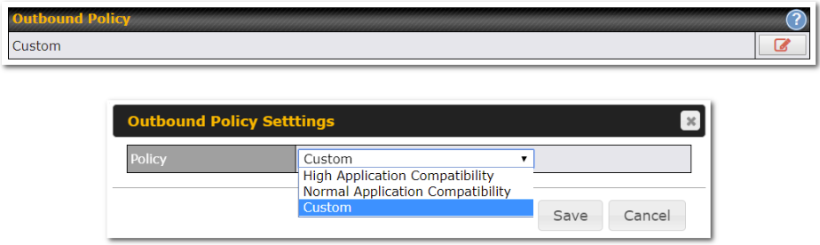
A selection menu will appear, giving you the choice between three different Outbound Policy Settings:
| Outbound Policy Settings | |
| High Application Compatibility | Outbound traffic from a source LAN device is routed through the same WAN connection regardless of the destination Internet IP address and protocol. This option provides the highest application compatibility. |
| Normal Application Compatibility | Outbound traffic from a source LAN device to the same destination Internet IP address will be routed through the same WAN connection persistently, regardless of protocol. This option provides high compatibility to most applications, and users still benefit from WAN link load balancing when multiple Internet servers are accessed. |
| Custom | Outbound traffic behavior can be managed by defining rules in a custom rule table. A default rule can be defined for connections that cannot be matched with any of the rules. |
Adding Rules for Outbound Policy
The menu underneath enables you to define Outbound policy rules:
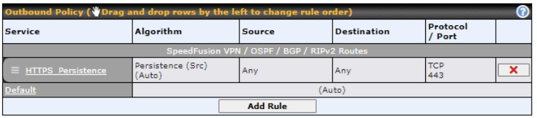
The bottom-most rule is Default. Edit this rule to change the device’s default manner of controlling outbound traffic for all connections that do not match any of the rules above it. Under the Service heading, click Default to change these settings.
To rearrange the priority of outbound rules, drag and drop them into the desired sequence.
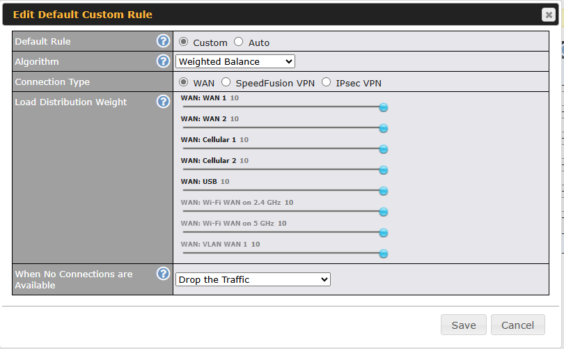
By default, Auto is selected as the Default Rule. You can select Custom to change the algorithm to be used. Please refer to the upcoming sections for the details on the available algorithms.
(Connection Type option available only when Weighted Balance is chosen and Speed Fusion or Route-based IPsec has been configured.)
To create a custom rule, click Add Rule at the bottom of the table.
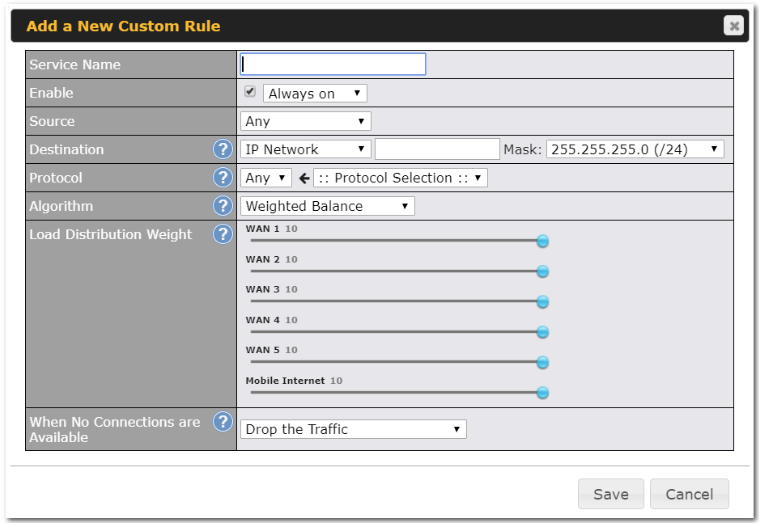
| New Custom Rule Settings | |
| Service Name | This setting specifies the name of the outbound traffic rule. |
| Enable | This setting specifies whether the outbound traffic rule takes effect. When Enable is checked, the rule takes effect: traffic is matched and actions are taken by the Pepwave router based on the other parameters of the rule. When Enable is unchecked, the rule does not take effect: the Pepwave router disregards the other parameters of the rule.
Click the drop-down menu next to the checkbox to apply a time schedule to this custom rule. |
| Source | This specifies the source IP address(es) and port number(s) to be matched for the firewall rule. Any, IP Address, IP Network, MAC Address, Client Type (for Outbound and Internal Firewall only), and Client’s Associated SSID can be specified as the Source setting, as indicated in the following screenshots:
When you select Client Type as the Source, a drop-down list will appear for you to choose the different types of client devices.
In addition, a single port, or a range of ports, can be specified for the Source settings. |
| Destination | This specifies the destination IP address(es) and port number(s) to be matched for the firewall rule. Any, IP Address, IP Network, Domain Name, SpeedFusion Connect, and SpeedFusion VPN Profile can be specified as the Destination setting, as indicated in the following screenshots:
In addition, a single port or a range of ports can be specified for the settings. |
| Protocol and Port | This setting specifies the IP protocol and port of traffic that matches this rule. Via a drop-down menu, the following protocols can be specified:
Alternatively, the Protocol Selection Tool drop-down menu can be used to automatically fill in the protocol and port number of common Internet services (e.g., HTTP, HTTPS, etc.) After selecting an item from the Protocol Selection Tool drop-down menu, the protocol and port number remain manually modifiable. |
| Algorithm | This setting specifies the behavior of the Pepwave router for the custom rule.
One of the following values can be selected (Note that some Pepwave routers provide only some of these options):
For a full explanation of each Algorithm, please see the following article: https://forum.peplink.com/t/exactly-how-do-peplinks-load-balancing-algorithmns-work/8059 |
| Connection Type | This is to define which connection to forward the traffic.
|
| Load Distribution Weight | This is to define the outbound traffic weight ratio for each WAN connection. |
| When No connections are available | This field allows you to configure the default action when all the selected Connections are not available.
Drop the Traffic – Traffic will be discarded. Use Any Available Connections – Traffic will be routed to any available Connection, even if it is not selected in the list. Fall-through to Next Rule – Traffic will continue to match the next Outbound Policy rule just like this rule is inactive. |
| Terminate Sessions on Connection Recovery | This setting specifies whether to terminate existing IP sessions on a less preferred WAN connection in the event that a more preferred WAN connection is recovered. This setting is applicable to the Priority algorithms. By default, this setting is disabled. In this case, existing IP sessions will not be terminated or affected when any other WAN connection is recovered. When this setting is enabled, existing IP sessions may be terminated when another WAN connection is recovered, such that only the preferred healthy WAN connection(s) is used at any point in time. |
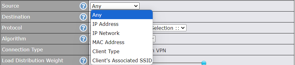

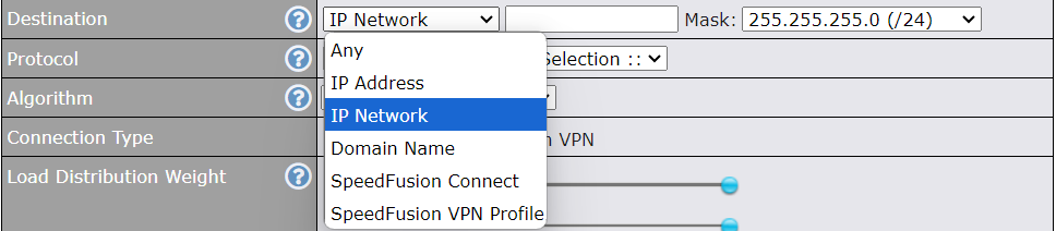

Algorithm: Weighted Balance#
This setting specifies the ratio of WAN connection usage to be applied on the specified IP protocol and port. This setting is applicable only when Algorithm is set to Weighted Balance.
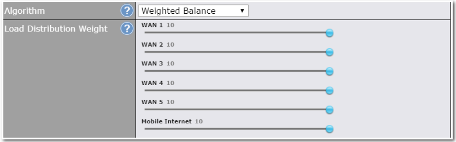
The amount of matching traffic that is distributed to a WAN connection is proportional to the weight of the WAN connection relative to the total weight. Use the sliders to change each WAN’s weight.
For example, with the following weight settings:
- Ethernet WAN1: 10
- Ethernet WAN2: 10
- Wi-Fi WAN: 10
- Cellular 1: 10
- Cellular 2: 10
- USB: 10
Total weight is 60 = (10 +10 + 10 + 10 + 10 + 10).
Matching traffic distributed to Ethernet WAN1 is 16.7% = (10 / 60 x 100%.
Matching traffic distributed to Ethernet WAN2 is 16.7% = (10 / 60) x 100%.
Matching traffic distributed to Wi-Fi WAN is 16.7% = (10 / 60) x 100%.
Matching traffic distributed to Cellular 1 is 16.7% = (10 / 60) x 100%.
Matching traffic distributed to Cellular 2 is 16.7% = (10 / 60) x 100%.
Matching traffic distributed to USB is 16.7% = (10 / 60) x 100%.
Algorithm: Priority#
This setting specifies the priority of the WAN connections used to route the specified network service. The highest priority WAN connection available will always be used for routing the specified type of traffic. A lower priority WAN connection will be used only when all higher priority connections have become unavailable.
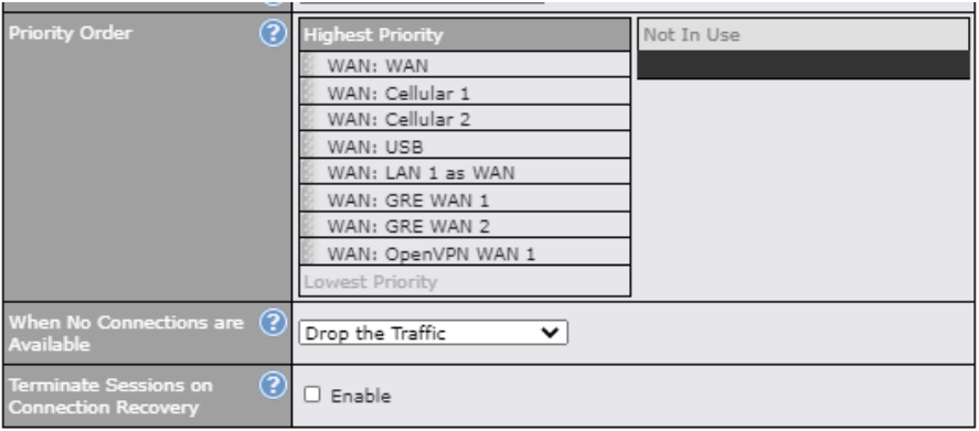
Starting from Firmware 5.2, outbound traffic can be prioritized to go through SpeedFusionTM connection(s). By default, VPN connections are not included in the priority list.
| Tip |
| Configure multiple distribution rules to accommodate different kinds of services. |
Algorithm: Overflow#
The traffic matching this rule will be routed through the healthy WAN connection that has the highest priority and is not in full load. When this connection gets saturated, new sessions will be routed to the next healthy WAN connection that is not in full load.
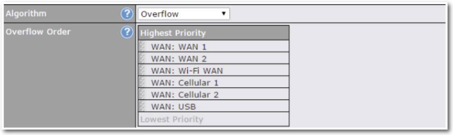
Drag and drop to specify the order of WAN connections to be used for routing traffic. Only the highest priority healthy connection that is not in full load will be used.
Algorithm: Least Used#
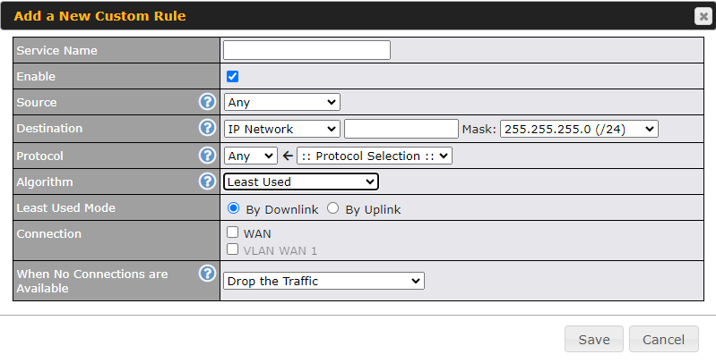
By default, traffic matching this rule will be routed through the healthy WAN connection that is selected in the ‘Connection‘ and has the most available download bandwidth. You can change it to ‘By Uplink’ to choose the connection that has the most available upload bandwidth.
The available download/upload bandwidth of a WAN connection is calculated from the total download/upload bandwidth specified on the WAN settings page and the current download/upload usage. The available bandwidth and WAN selection are determined every time an IP session is established.
Algorithm: Lowest Latency#
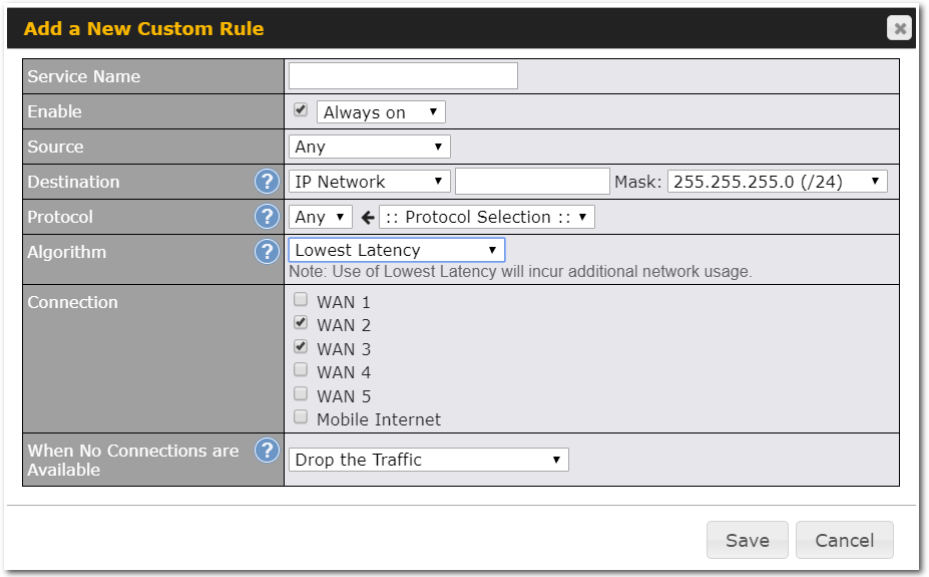
The traffic matching this rule will be routed through the healthy WAN connection that is selected in Connection and has the lowest latency. Latency checking packets are issued periodically to a nearby router of each WAN connection to determine its latency value. The latency of a WAN is the packet round trip time of the WAN connection. Additional network usage may be incurred as a result.
| Tip |
The roundtrip time of a 6M down/640k uplink can be higher than that of a 2M down/2M up link because the overall round trip time is lengthened by its slower upload bandwidth, despite its higher downlink speed. Therefore, this algorithm is good for two scenarios:
|
Algorithm : Fastest Response Time#
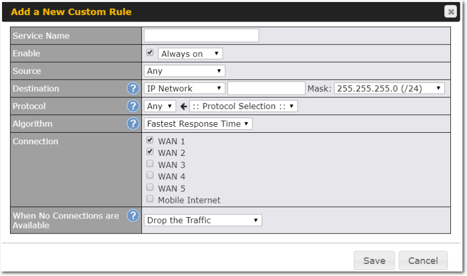
The Fastest response Time algorithm works as follows:
When a network session is created, the first outgoing packet of that particular session is duplicated to all the available WANs.
When the first response is received from a remote server, any further traffic for this session will be routed over that particular WAN connection for the fastest possible response time.
If any slower responses are received on other connections afterwards, they will be discarded.
Inbound Access#
Inbound access is also known as inbound port address translation. On a NAT WAN connection, all inbound traffic to the server behind the Peplink unit requires inbound access rules.
By the custom definition of servers and services for inbound access, Internet users can access the servers behind Peplink Balance. Advanced configurations allow inbound access to be distributed among multiple servers on the LAN.
| Important Note |
| Inbound access applies only to WAN connections that operate in NAT mode. For WAN connections that operate in drop-in mode or IP forwarding, inbound traffic is forwarded to the LAN by default. |
Servers#
The settings to configure servers on the LAN are located at Network>Inbound Access>Servers.
Inbound connections from the Internet will be forwarded to the specified Inbound IP address(es) based on the protocol and port number. When more than one server is defined, requests will be distributed to the servers in the weight ratio specified for each server.
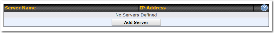
To define a new server, click Add Server, which displays the following screen:
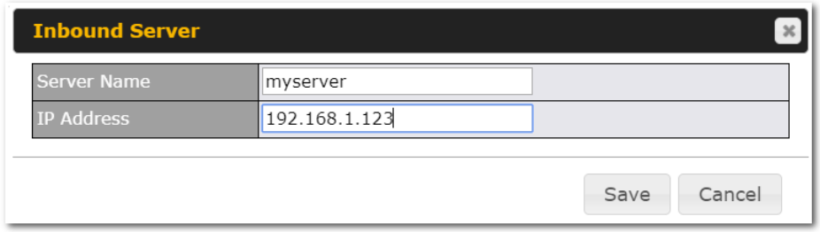
Enter a valid server name and its corresponding LAN IP address. Upon clicking Save after entering required information, the following screen appears.
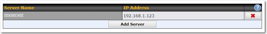
To define additional servers, click Add Server and repeat the above steps.
Services#
Services are defined at Network>Inbound Access>Services.
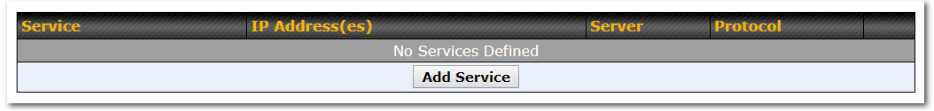
| Tip |
| At least one server must be defined before services can be added. |
To define a new service, click the Add Service button, upon which the following menu appears:
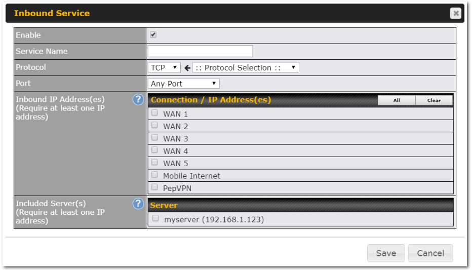
| Services Settings | |
| Enable | This setting specifies whether the inbound service rule takes effect.
When Yes is selected, the inbound service rule takes effect. If the inbound traffic matches the specified IP protocol and port, action will be taken by the Peplink Balance based on the other parameters of the rule. When No is selected, the inbound service rule does not take effect. The Peplink Balance will disregard the other parameters of the rule. |
| Service Name | This setting identifies the service to the system administrator. Only alphanumeric and the underscore “_” characters are valid. |
| IP Protocol | The IP Protocol setting, along with the Port setting, specifies the protocol of the service as TCP, UDP, ICMP, or IP. Inbound traffic that matches the specified IP Protocol and Port(s) will be forwarded to the LAN hosts specified by the Servers setting.
Upon choosing a protocol, the Protocol Selection Tool drop-down menu can be used to automatically the port information of common Internet services (e.g. HTTP, HTTPS, etc.). After selecting an item from the Protocol Selection Tool drop-down menu, the protocol and the port number will remain manually modifiable. |
| Port | The Port setting specifies the port(s) that correspond to the service, and can be configured to behave in one of the following manners:
Any Port, Single Port, Port Range, Port Map, and Range Mapping
Any Port: all traffic that is received by the Peplink Balance via the specified protocol is forwarded to the servers specified by the Servers setting. For example, if IP Protocol is set to TCP and Port is set to Any Port, then all TCP traffic will be forwarded to the configured servers.
Single Port: traffic that is received by the Peplink Balance via the specified protocol at the specified port is forwarded via the same port to the servers specified by the Servers setting. For example, if IP Protocol is set to TCP, Port is set to Single Port, and Service Port is set to 80, then TCP traffic received on Port 80 will be forwarded to the configured servers via port 80.
Port Range: traffic that is received by the Peplink Balance via the specified protocol at the specified port range is forwarded via the same respective ports to the LAN hosts specified by the Servers setting. For example, if IP Protocol is set to TCP, Port is set to Port Range, and Service Port set to 80-88, then TCP traffic received on ports 80 through 88 will be forwarded to the configured servers via the respective ports.
Port Mapping: traffic that is received by the Peplink Balance via the specified protocol at the specified port is forwarded via a different port to the servers specified by the Servers setting. For example, if IP Protocol is set to TCP, Port is set to Port Mapping, Service Port is set to 80, and Map to Port is set to 88, then TCP traffic on port 80 is forwarded to the configured servers via port 88. (Please see below for details on the Servers setting.)
Range Mapping: traffic that is received by Peplink Balance via the specified protocol at the specified port range is forwarded via a different port to the servers specified by the Servers setting. |
| Inbound IP Address(es) | This setting specifies the WAN connections and Internet IP address(es) from which the service can be accessed. |
| Included Server(s) | This setting specifies the LAN servers that handle requests for the service, and the relative weight values. The amount of traffic that is distributed to a server is proportional to the weight value assigned to the server relative to the total weight.
Example: With the following weight settings on a Peplink Balance:
The total weight is 15 = (10 + 5) Matching traffic distributed to demo_server_1:67% = (10 / 15) x 100% Matching traffic distributed to demo_server_2:33% = (5 / 15) x 100% |


UPnP / NAT-PMP Settings#
UPnP and NAT-PMP are network protocols which allow a computer connected to the LAN port to automatically configure the router to allow parties on the WAN port to connect to itself. That way, the process of inbound port forwarding becomes automated.
When a computer creates a rule using these protocols, the specified TCP/UDP port of all WAN connections’ default IP address will be forwarded.
Check the corresponding box(es) to enable UPnP and/or NAT-PMP. Enable these features only if you trust the computers connected to the LAN ports.
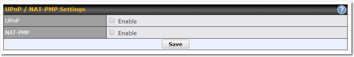
When the options are enabled, a table listing all the forwarded ports under these two protocols can be found at Network > Services > UPnP / NAT-PMP.
DNS Settings#
The built-in DNS server functionality of the Peplink Balance facilitates inbound load balancing. With this functionality, NS/SOA DNS records for a domain name can be delegated to the Internet IP address(es) of the Peplink Balance. Upon receiving a DNS query, the Peplink Balance can return (as an “A” record) the IP address for the domain name on the most appropriate healthy WAN connection. It can also act as a generic DNS server for hosting “A”, “CNAME”, “MX”, “TXT” and “NS” records.
The settings for defining the DNS records to be hosted by the Peplink Balance are located at Network > Inbound Access > DNS Settings.
Note: DNS names may only contain alphanumeric characters (A-Z and 0-9), hyphens (-), and periods (.). The period is only allowed when it is used to delimit the components of domain style names.
For more information, see the following websites:
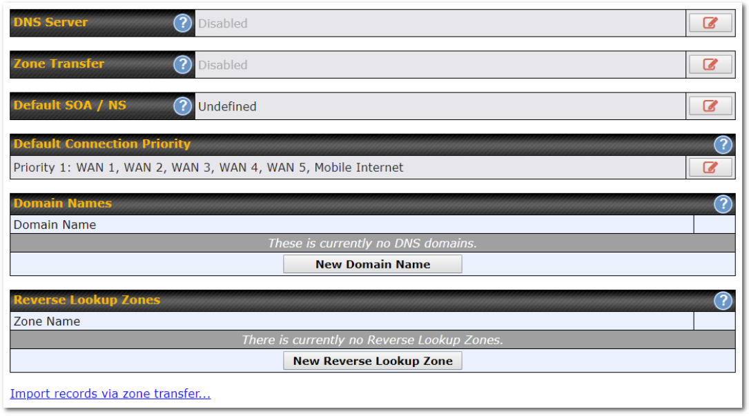
| DNS Settings | |
| DNS Servers | This setting specifies the WAN IP addresses on which the DNS server of the Peplink Balance should listen.
If no addresses are selected, the inbound link load balancing feature will be disabled and the Peplink Balance will not respond to DNS requests. To specify and/or modify the IP addresses on which the DNS server should listen, click the button that corresponds to DNS Server, and a selection screen will be displayed: To specify the Internet IP addresses on which the DNS server should listen, select the desired WAN connection then select the desired associated IP addresses. (Multiple items in the list can be selected by holding CTRL and clicking on the items.) Click Save to save the settings when configuration is complete. |
| Zone Transfer | This setting specifies the IP address(es) of the secondary DNS server(s)authorized to retrieve zone records from the DNS server of the Peplink Balance.
The zone transfer server of the Peplink Balance listens on TCP port 53. The Peplink Balance serves both the clients that are accessing from the specified IP addresses, and the clients that are accessing its LAN interface. |
| Routing Control by Subnet Database | When this function is enabled, the system will check to see if an incoming DNS client is within any WAN’s ISP subnet. Only the matched WAN(s)’s IP addresses will be returned. Note that this feature is available only when a subnet database has been defined. |
| Default SOA / NS | Click the button to define a default SOA / NS record for all domain names.
When defining a default SOA record, Name Server IP Address is optional. If left blank, the Address (A) record for the same server should be defined manually in each domain. For defining default NS records, the host [domain] indicates that this record is for the domain name itself without a sub-domain prefix. To add a secondary NS server, just create a second NS record with the Host field left empty. When the entered name server is a fully qualified domain name (FQDN), the IP Address field will be disabled. |
| Default Connection Priority | Default Connection Priority defines the default priority group of each WAN connection in resolving A records. It applies to Address (A) records which have the Connection Priority set to Default. Please refer to Section 17.3.9 for details.
The WAN connection(s) with the highest priority (smallest number) will be chosen. Those with lower priorities will not be chosen in resolving A records unless the higher priority ones become unavailable. To specify the primary and backup connections, click the button that corresponds to Default Connection Priority. A selection screen will appear. Each WAN connection is associated with a priority number. Click Save to save the settings when configuration is complete. |
| Domain name | This section shows a list of domain names to be hosted by the Peplink Balance. Each domain can have its “NS”, “MX” and “TXT” records, and its sub-domains’ “A” and “CNAME” records. Add a new record by clicking the New Domain Name button. Click on a domain name to edit. Press the red X to remove a domain name. |
New Domain Name#
Upon clicking the New Domain Name button, and the following screen will appear:
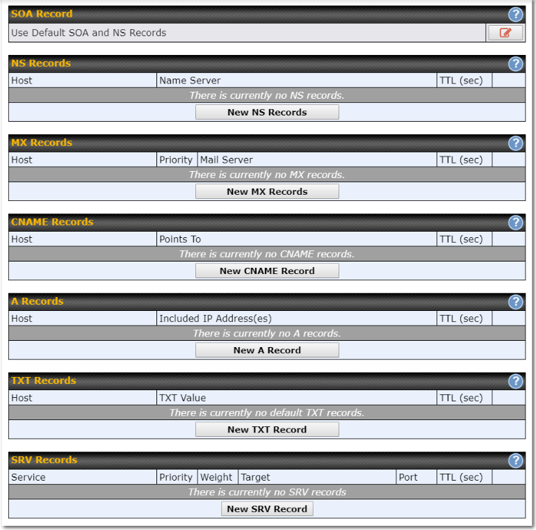
This page is for defining the domain’s SOA, NS, MX, CNAME, A, TXT, and SRV records. Seven tables are presented in this page for defining the five types of records.
SOA Records#
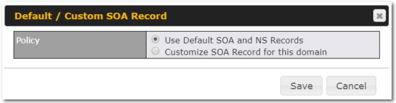
Click on the ![]() icon to choose whether to use the pre-defined default SOA record and NS records. If the option Use Default SOA and NS Records is selected, any changes made in the default SOA/NS records will be applied to this domain automatically. Otherwise, select the option Customize SOA Record for this domain to customize this domain’s SOA and NS records.
icon to choose whether to use the pre-defined default SOA record and NS records. If the option Use Default SOA and NS Records is selected, any changes made in the default SOA/NS records will be applied to this domain automatically. Otherwise, select the option Customize SOA Record for this domain to customize this domain’s SOA and NS records.
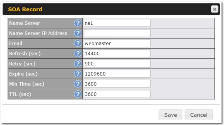
This table displays the current SOA record. When the option Customize SOA Record for this domain is selected, you can click the link Click here to define SOA record to create or click on the Name Server field to edit the SOA record.
In the SOA record, you have to fill out the fields Name Server, Name Server IP Address, Email, Refresh, Retry, Expire, Min Time, and TTL.
Default values are set for SOA and NS records,
- Name Server IP Address: This is the IP address of the authoritative name server. An entry in this field is optional. If the Balance is the authoritative name server of the domain, this field’s value should be the WAN connection’s name server IP address that is registered in the DNS registrar. If this field is entered, a corresponding A record for the name server will be created automatically. If it is left blank, the A record for the name server must be created manually.
- E-mail: Defines the e-mail address of the person responsible for this zone. Note: format should be mailbox-name.domain.com, e.g., hostmaster.example.com.
- Refresh: Indicates the length of time (in seconds) when the slave will try to refresh the zone from the master.
- Retry: Defines the duration (in seconds) between retries if the slave (secondary) fails to contact the master and the refresh (above) has expired.
- Expire: Indicates the time (in seconds) when the zone data is no longer authoritative. This option applies to slave DNS servers only.
- Min Time: Is the negative caching time which defines the time (in seconds) after an error record is cached.
- TTL (Time-to-Live): Defines the duration (in seconds) that the record may be cached.
NS Records#
The NS Records table shows the NS servers and TTL that correspond to the domain. The NS record of the name server defined in the SOA record is automatically added here.
To add a new NS record, click the New NS Records button in the NS Records box. Then the table will expand to look like the following:
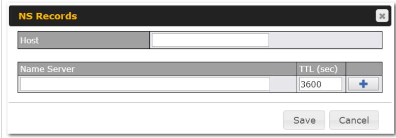
When creating an NS record for the domain itself (not a sub-domain), the Host field should be left blank.
Enter a name server host name and its IP address into the corresponding boxes. The host name can be a non-FQDN (fully qualified domain name). Please be sure that a corresponding A record is created. Click the ![]() button on the right to finish and to add other name servers. Click the Save button to save your changes.
button on the right to finish and to add other name servers. Click the Save button to save your changes.
MX Records#
The MX Record table shows the domain’s MX records. To add a new MX record, click the New MX Records button in the MX Records box. Then the table will expand to look like the following:
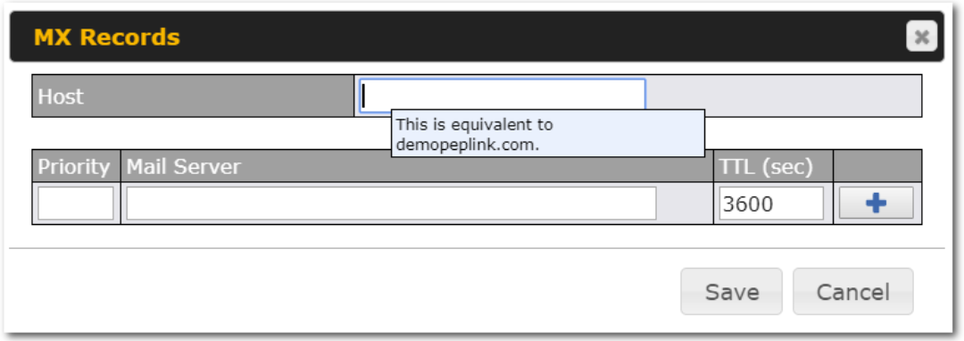
When creating an MX record for the domain itself (not a sub-domain), the Host field should be left blank.
For each record, Priority and Mail Server name must be entered. Priority typically ranges from 10 to 100. Smaller numbers have a higher priority. After finishing adding MX records, click the Save button.
CNAME Records#
The CNAME Record table shows the domain’s CNAME records. To add a new CNAME record, click the New CNAME Records button in the CNAME Record box. Then the table will expand to look like the following:

When creating a CNAME record for the domain itself (not a sub-domain), the Host field should be left blank.
The wildcard character “*”is supported in the Host field. The reference of “.domain.name” will be returned for every name ending with “.domain.name” except names that have their own records.
The TTL field tells the time to live of the record in external DNS caches.
A Records#
This table shows the A records of the domain name. To add an A record, click the New A Record button. The following screen will appear:
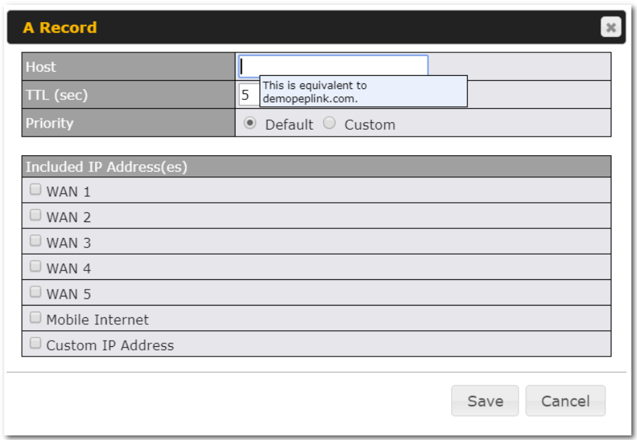
A record may be automatically added for the SOA records with a name server IP address provided.
| A Record | |
| Host Name | This field specifies the A record of this sub-domain to be served by the Peplink Balance. The wildcard character “*” is supported. The IP addresses of “*.domain.name” will be returned for every name ending with “.domain.name” except names that have their own records. |
| TTL | This setting specifies the time to live of this record in external DNS caches.
In order to reflect any dynamic changes on the IP addresses in case of link failure and recovery, this value should be set to a smaller value, e.g., 5 secs, 60 secs, etc. |
| Priority | This option specifies the priority of different connections.
Select the Default option to apply the Default Connection Priority (refer to the table shown on the main DNS settings page) to an A record. To customize priorities, choose the Custom option and a priority selection table will be shown at the bottom. |
| Included IP Address(es) | This setting specifies lists of WAN-specific Internet IP addresses that are candidates to be returned when the Peplink Balance responds to DNS queries for the domain name specified by Host Name.
The IP addresses listed in each box as default are the Internet IP addresses associated with each of the WAN connections. Static IP addresses that are not associated with any WAN can be entered into the Custom IP list. A PTR record is also created for each custom IP. For WAN connections that operate under drop-in mode, there may be other routable IP addresses in addition to the default IP address. Therefore, the Peplink Balance allows custom Internet IP addresses to be added manually via filling the text box on the right-hand side and clicking the Only the checked IP addresses in the lists are candidates to be returned when responding to a DNS query. If a WAN connection is down, the corresponding set of IP addresses will not be returned. However, the IP addresses in the Custom IP Address field will always be returned. If the Connection Priority field is set to Custom, you can also specify the usage priority of each WAN connection. Only selected IP address(es) of available connection(s) with the highest priority, and custom IP addresses will be returned. By default, Connection Priority is set to Default. |
TXT Records#
This table shows the TXT record of the domain name.

To add a new TXT record, click the New TXT Record button in the TXT Records box. Click the Edit button to edit the record. The time-to-live value and the TXT record’s value can be entered. Click the Save button to finish.
When creating a TXT record for the domain itself (not a sub-domain), the Host field should be left blank.
The maximum size of the TXT Value is 255 bytes.
After editing the five types of records, you can leave the page by simply going to another section of the web admin interface.
SRV Records#
To add a new SRV record, click the New SRV Record button in the SRV Records box.
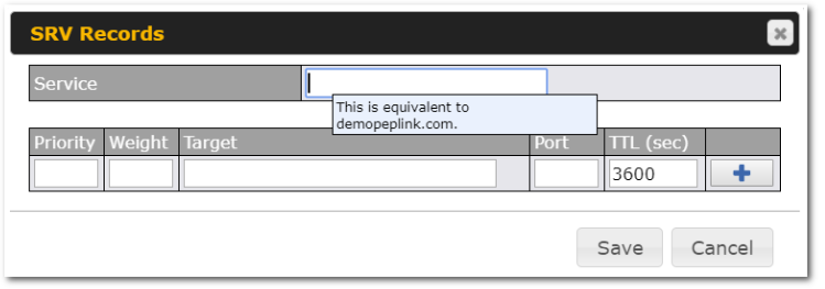
- Service: The symbolic name of the desired service.
- Priority: Indicates the priority of the target; the smaller the value, the higher the priority.
- Weight: A relative weight for records with the same priority.
- Target: The canonical hostname of the machine providing the service.
- Port: Enter the TCP or UDP port number on which the service is to be found.
Reverse Lookup Zones#
Reverse lookup zones can be configured in Network>Inbound Access>DNS Settings.
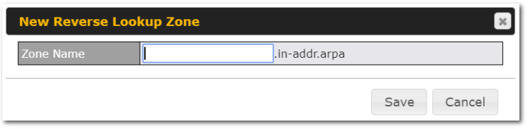
Reverse lookup refers to performing a DNS query to find one or more DNS names associated with a given IP address.
The DNS stores IP addresses in the form of specially formatted names as pointer (PTR) records using special domains/zones. The zone is in-addr.arpa.
To enable DNS clients to perform a reverse lookup for a host, perform two steps:
- Create a reverse lookup zone that corresponds to the subnet network address of the host.
In the reverse lookup zone, add a pointer (PTR) resource record that maps the host IP address to the host name.
- Click the New Reverse Lookup Zone button and enter a reverse lookup zone name. If you are delegated the subnet 11.22.33.0/24, the Zone Name should be 33.22.11.in-arpa.addr. PTR records for 11.22.33.1, 11.22.33.2, … 11.22.33.254 should be defined in this zone where the host IP numbers are 1, 2, … 254, respectively.
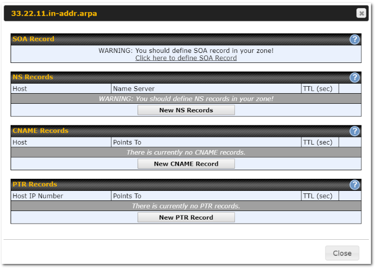
SOA Record#
You can click the link Click here to define SOA record to create or click on the Name Server field to edit the SOA record.
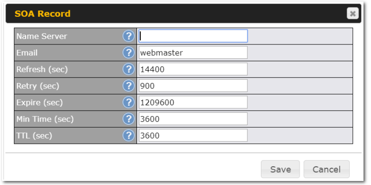
Name Server: Enter the NS record’s FQDN server name here.
For example:
“ns1.mydomain.com” (equivalent to “www.1stdomain.com.”)
“ns2.mydomain.com.”
Email, Refresh, Retry, Expire, Min Time, and TTL are entered in the same way as in the forward zone. Please refer to Section 17.3.5 for details.
NS Records#
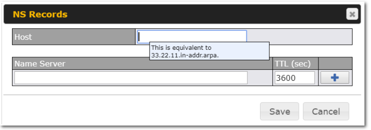
The NS record of the name server defined in the SOA record is automatically added here. To create a new NS record, click the New NS Records button.
When creating an NS record for the reverse lookup zone itself (not a sub-domain or dedicated zone), the Host field should be left blank. Name Server must be a FQDN.
CNAME Records#
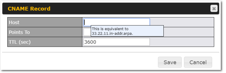
To create a new CNAME record, click the New CNAME Record button.
CNAME records are typically used for defining classless reverse lookup zones. Subnetted reverse lookup zones are further described in RFC 2317, “Classless IN-ADDR.ARPA delegation.”
PTR Records#
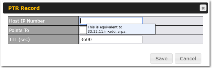
To create a new PTR record, click the New PTR Record button.
For Host IP Number field, enter the last integer in the IP address of a PTR record. For example. for the IP address 11.22.33.44, where the reverse lookup zone is 33.22.11.in-arpa.addr, the Host IP Number should be 44.
The Points To field defines the host name which the PTR record should be pointed to. It must be a FQDN.
DNS Record Import Wizard#
At the bottom of the DNS settings page, the link Import records via zone transfer…is used to import DNS record using an import wizard.
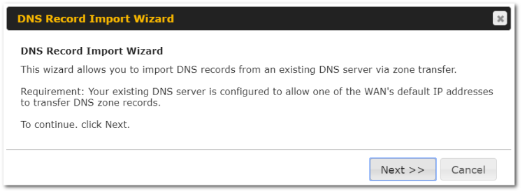
- Select Next >> to continue.
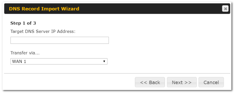
- In the Target DNS Server IP Address field, enter the IP address of the DNS server.
- In the Transfer via…field, choose the connection which you would like to transfer through.
- Select Next >> to continue.
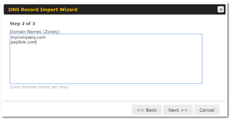
- In the blank space, enter the Domain Names (Zones) which you would like to assign the IP address entered in the previous step. Enter one domain name per line.
- Select Next >> to continue.
| Important Note |
| If you have entered domain(s) which already exist in your settings, a warning message will appear. Select Next >> to overwrite the existing record or << Back to go back to the previous step.
|
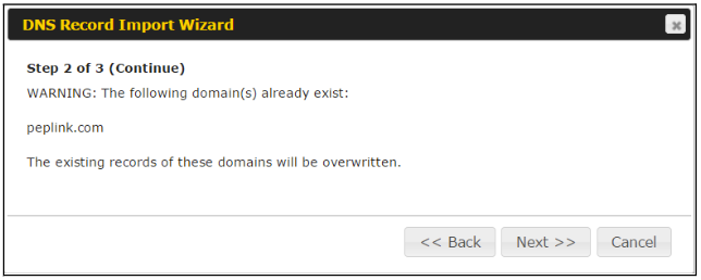
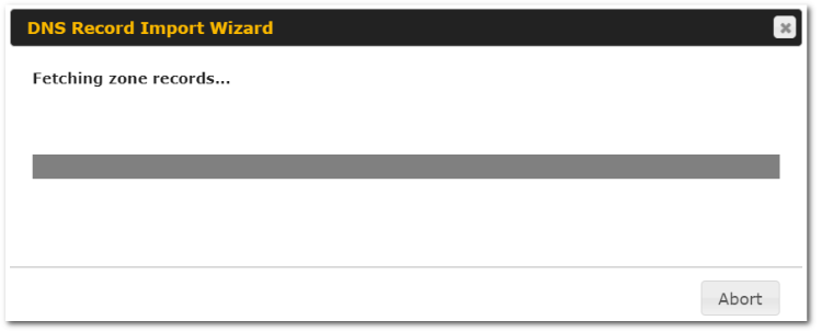
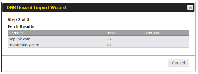
After the zone records process have been fetched, the fetch results would be shown as above. You can view import details by clicking the corresponding hyperlink on the right-hand side.
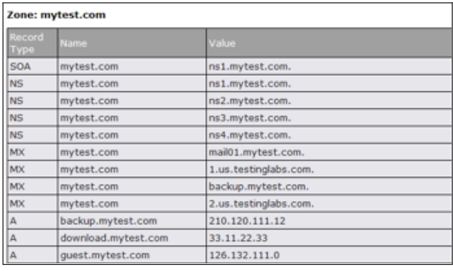
NAT Mappings#
The Peplink Balance allows the IP address mapping of all inbound and outbound NATed traffic to and from an internal client IP address.
NAT mappings can be configured at Network>NAT Mappings.
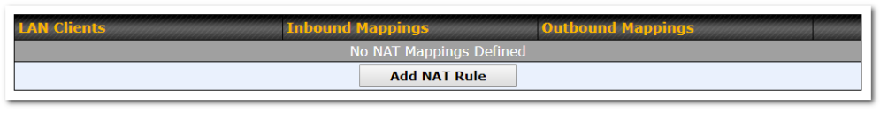
To add a rule for NAT mappings, click Add NAT Rule and the following screen will be displayed:
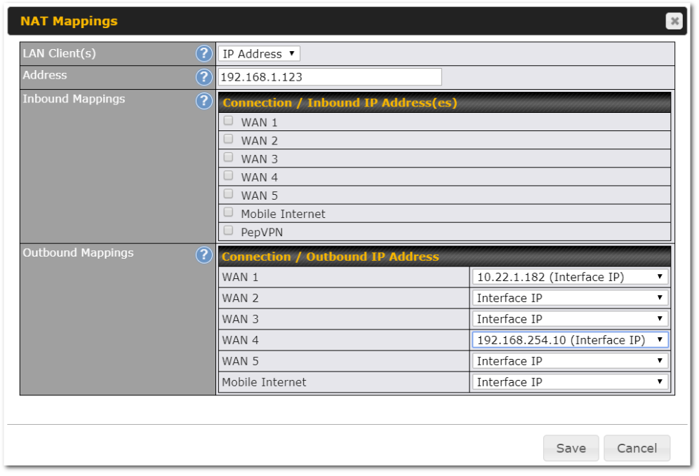
| NAT Mapping Settings | |
| LAN Client(s) | NAT Mapping rules can be defined for a single LAN IP Address, an IP Range, or an IP Network. |
| Address | This refers to the LAN host’s private IP address. The system maps this address to a number of public IP addresses (specified below) in order to facilitate inbound and outbound traffic. This option is only available when IP Address is selected. |
| Range | The IP range is a contiguous group of private IP addresses used by the LAN host. The system maps these addresses to a number of public IP addresses (specified below) to facilitate outbound traffic. This option is only available when IP Range is selected. |
| Network | The IP network refers to all private IP addresses and ranges managed by the LAN host. The system maps these addresses to a number of public IP addresses (specified below) to facilitate outbound traffic. This option is only available when IP Network is selected. |
| Inbound Mappings | This setting specifies the WAN connections and corresponding WAN-specific Internet IP addresses on which the system should bind. Any access to the specified WAN connection(s) and IP address(es) will be forwarded to the LAN host. This option is only available when IP Address is selected in the LAN Client(s) field.
Note 1: Inbound mapping is not needed for WAN connections in drop-in mode or IP forwarding mode. Note 2: Each WAN IP address can be associated to one NAT mapping only. |
| Outbound Mappings | This setting specifies the WAN IP addresses should be used when an IP connection is made from a LAN host to the Internet.
Each LAN host in an IP range or IP network will be evenly mapped to one of each selected WAN’s IP addresses (for better IP address utilization) in a persistent manner (for better application compatibility). Note 1: If you do not want to use a specific WAN for outgoing accesses, you should still choose default here, then customize the outbound access rule in the Outbound Policy section. Note 2: WAN connections in drop-in mode or IP forwarding mode are not shown here. |
Click Save to save the settings when configuration has been completed.
| Important Note |
| Inbound firewall rules override inbound mapping settings. |
MediaFast#
MediaFast settings can be configured by navigating to Network > MediaFast.
Setting Up MediaFast Content Caching
To access MediaFast content caching settings, select Network > MediaFast.
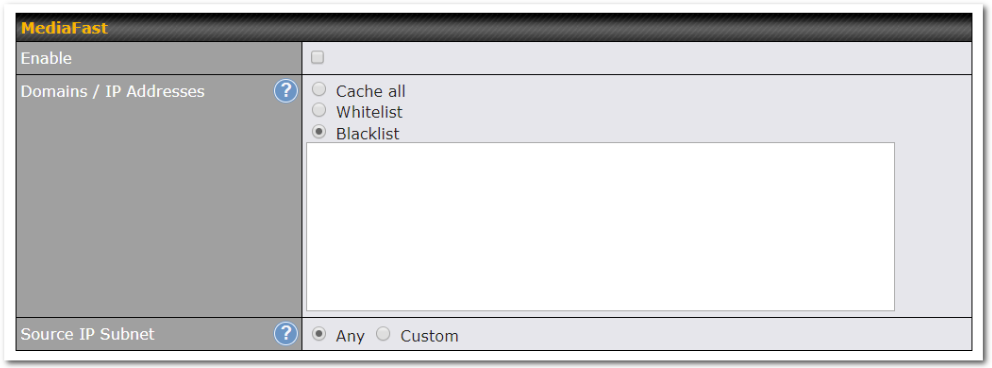
| MediaFast | |
| Enable | Click the checkbox to enable MediaFast content caching. |
| Domains / IP Addresses | Choose to Cache on all domains, or enter domain names and then choose either Whitelist (cache the specified domains only) or Blacklist (do not cache the specified domains). |
| Source IP Subnet | This setting allows caching to be enabled on custom subnets only. If “Any” is selected, then caching will apply to all subnets. |
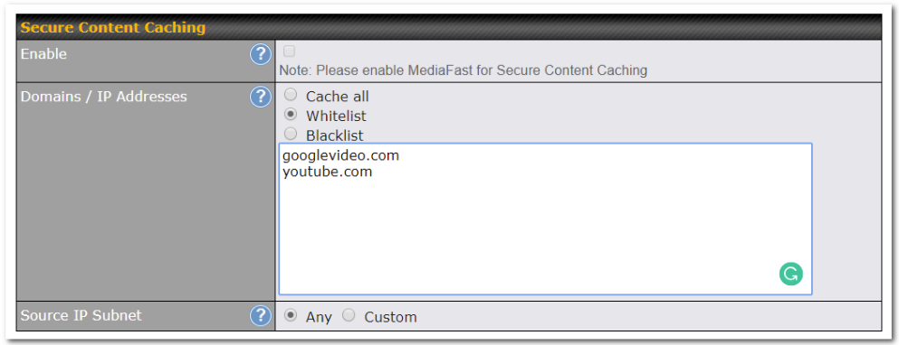
The Secure Content Caching menu operates identically to the MediaFast menu, except it is for secure content cachting accessible through https://.
In order for Mediafast devices to cache and deliver HTTPS content, every client needs to have the necessary certificates installed*.
*See https://forum.peplink.com/t/certificate-installation-for-mediafast-https-caching/
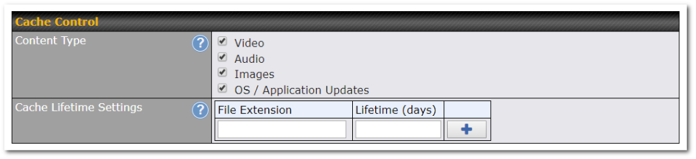
| Cache Control | |
| Content Type | Check these boxes to cache the listed content types or leave boxes unchecked to disable caching for the listed types. |
| Cache Lifetime Settings | Enter a file extension, such as JPG or DOC. Then enter a lifetime in days to specify how long files with that extension will be cached. Add or delete entries using the controls on the right. |
Viewing MediaFast Statistics
To get details on storage and bandwidth usage, select Status>MediaFast.
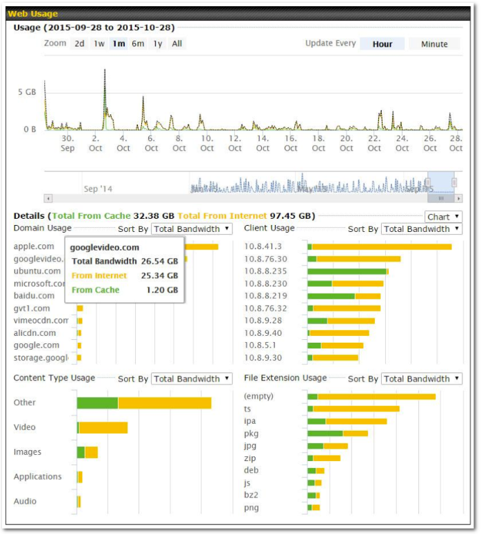
Prefetch Schedule
Content prefetching allows you to download content on a schedule that you define, which can help to preserve network bandwidth during busy times and keep costs down. To access MediaFast content prefetching settings, select Network > MediaFast > Prefetch Schedule.
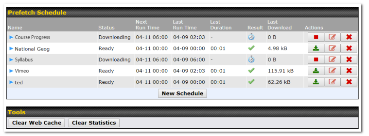
| Prefetch Schedule Settings | |
| Name | This field displays the name given to the scheduled download. |
| Status | Check the status of your scheduled download here. |
| Next Run Time/Last Run Time | These fields display the date and time of the next and most recent occurrences of the scheduled download. |
| Last Duration | Check this field to ensure that the most recent download took as long as expected to complete. A value that is too low might indicate an incomplete download or incorrectly specified download target, while a value that is too long could mean a download with an incorrectly specified target or stop time. |
| Result | This field indicates whether downloads are in progress ( |
| Last Download | Check this field to ensure that the most recent download file size is within the expected range. A value that is too low might indicate an incomplete download or incorrectly specified download target, while a value that is too long could mean a download with an incorrectly specified target or stop time. This field is also useful for quickly seeing which downloads are consuming the most storage space. |
| Actions | To begin a scheduled download immediately, click To cancel a scheduled download, click To edit a scheduled download, click To delete a scheduled download, click |
| New Schedule | Click to begin creating a new scheduled download. Clicking the button will cause the following screen to appear:
Simply provide the requested information to create your schedule. |
| Clear Web Cache | Click to clear all cached content. Note that this action cannot be undone. |
| Clear Statistics | Click to clear all prefetch and status page statistics. |
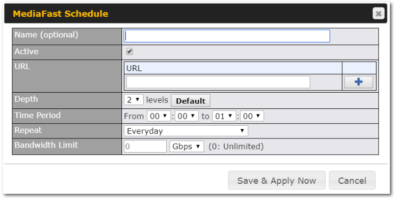
Edge Computing#
ContentHub allows you to deliver webpages and applications to users connected to the SSID using the local storage on your router. Users will be able to access news, articles, videos, and access your web app without the need for internet access.
The ContentHub can be used to provide infotainment to connected users on transport.
ContentHub storage needs to be configured before content can be uploaded to the ContentHub. Click on the link on the information panel to configure storage.

To access ContentHub, navigate to Network > ContentHub and check the Enable box.:
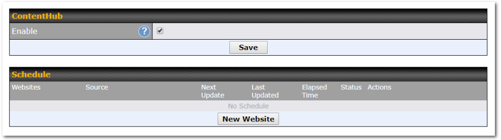
On an external server, configure content (a website or application) that will be synced to the ContentHub. For example, an html5 website.
To configure a website or application as content, follow the steps below.
Configure a website for the ContentHub#
This option allows you to sync a website to the Peplink router. This website will then be published with the specified domain from the router itself and makes the content available to the client via the HTTP/HTTPS protocol.
Only FTP sync is supported for this type of ContentHub content.
The content should be uploaded to an FTP server before you sync it with ContentHub.
Click New Website and a window with the following configuration options will appear:
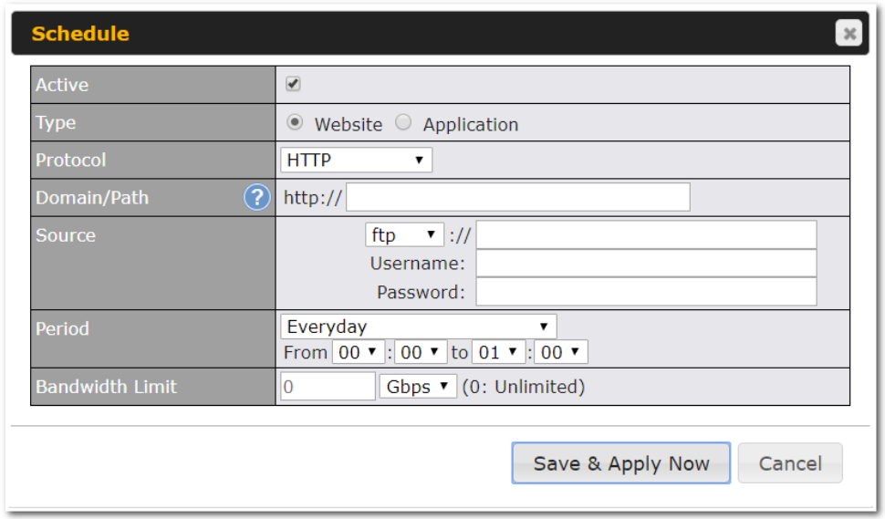
| Schedule | |
| Active | Checking the box toggles the activation of the content. |
| Type | Select the type of content: Website or Application. |
| Protocol | Configure the protocol to be used: HTTP, HTTPS or both. |
| Domain/Path | Enter the URL for the ContenHub to use as the domain name for client access (such as http://mytest.com). |
| Method | Only applicable for Application type content. Choose between sync or file upload. |
| Source | Enter the details of the server that the content will be downloaded from. Enter credentials under Username and Password. |
| Period | This field determines how often the router will search for updates to the source content. |
| Bandwidth Limit | Set a bandwidth limit for clients. |
Click “Save & Apply Now” to activate the changes. A screenshot of the display after configuration is shown below:
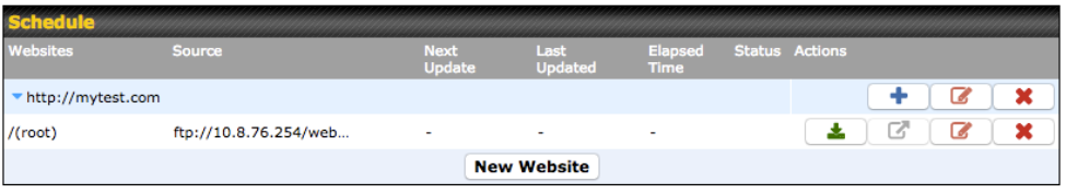
The content will be synced regularly according to the time set in the Period that was configured earlier.
If you want to activate the sync manually, you can click the “![]() ” icon. The “Status” column will display the sync progress. When the sync is completed, a summary will be displayed, as shown in the screenshot below:
” icon. The “Status” column will display the sync progress. When the sync is completed, a summary will be displayed, as shown in the screenshot below:
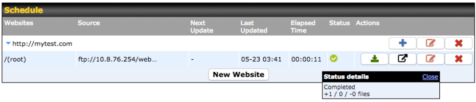
To access the content, open a browser in the MFA’s client and enter the domain details that were configured earlier (such as http://mytest.com).
Configure an application for the ContentHub#
MediaFast routers allow you to configure and publish any application from the router itself by using one of the supported frameworks below:
- Python (version 2.7.12)
- Ruby (version 2.3.3)
- Node.js (version 6.9.2)
Install the desired framework under “Package Manager” as shown below:
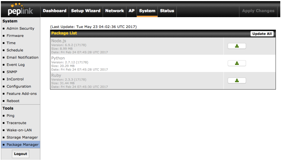
After installing the framework, change the ”Type” to “Application” and configure the website.
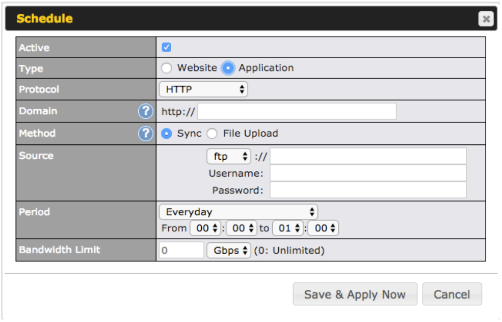
The setting is the same as the Website type (refer to the description in the section above).
Application type content need to be packed as explained below:
- Implement two bash script files, start.sh and stop.sh in the root folder, to start and stop your application. The MediaFast router will only execute start.sh and stop.sh when the corresponding website is enabled and disabled respectively.
- Compress the application files and the bash script to .tar.gz format.
- Upload this tar file to the router.
MDM Settings#
In addition to performing content caching, MediaFast-enabled routers can also serve as an MDM, administrating to client devices. To access MDM Settings, navigate to Network > MDM Settings:
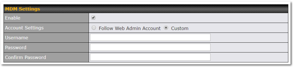
| MDM Settings | |
| Enable | Click this checkbox to enable MDM on your router. |
| Account Settings | Click Follow Web Admin Account to allow client devices to use the built-in administrator account when performing MDM. Set Custom to specify a username and password your router will use to log into your client devices. |
Please refer to the knowledgebase for information about enrolling client devices to MDM:
https://forum.peplink.com/t/how-to-enroll-a-device-to-the-mdm-server/8454
Docker#
For non-MFA/Edge Computing devices, you can plug in a USB as storage for installing or running Docker Containers on your device. After plugging in the device, under “System → Tools → External Storage” you will be able to see the USB details you plug in.
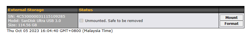
You might need to format your USB to the supported format to be able to use by the device. To format your USB, click “Format” button and type in the encryption key as following. The encryption key is used everytime for the USB to mount in the device.
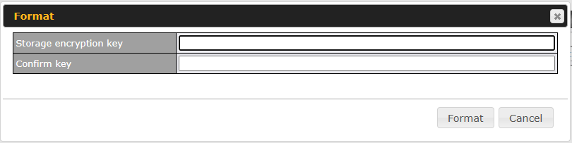
After a while, the status will change to “In use” as below.
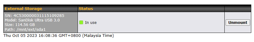
KVM#
MediaFast-enabled routers now support KVM. Users will need to download and install the Virtual Machine Manager to manage the KVM virtual machines. Through this, users can virtualize a Linux environment.
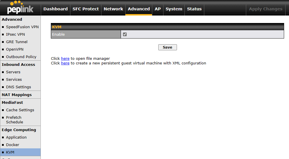
For detailed configuration instructions, please refer to our knowledge base articles:
- Create persistent guest virtual machines with XML configuration. After clicking ‘here,’ a text box will appear. Enter the code and choose “Start now” and “Autostart at boot”. Finally, click “Create” to initiate the VM configuration.
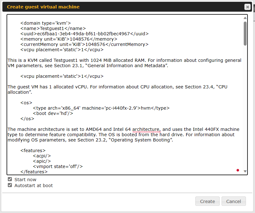
- How to install a Virtual Machine on Peplink/Pepwave – MediaFast/ContentHub Routers
- How to Install Virtual Machine with USB storage on Peplink/Pepwave – MediaFast/ContentHub Routers
Captive Portal#

The captive portal serves as a gateway that clients have to pass if they wish to access the Internet using your router. To configure, navigate to Network > Captive Portal.
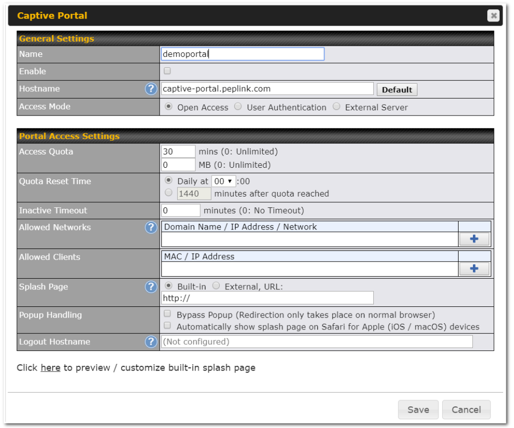
| Captive Portal Settings | |
| Enable | Check Enable and then, optionally, select the LANs/VLANs that will use the captive portal. |
| Hostname | To customize the portal’s form submission and redirection URL, enter a new URL in this field. To reset the URL to factory settings, click Default. |
| Access Mode | Click Open Access to allow clients to freely access your router. Click User Authentication to force your clients to authenticate before accessing your router. Select External Server to use the Captive Portal with a HotSpot system.As described in the following knowledgebase article:https://forum.peplink.com/t/using-hotspotsystem-wi-fi-on-pepwave-max-routers/ |
| RADIUS Server | This authenticates your clients through a RADIUS server. After selecting this option, you will see the following fields:
Fill in the necessary information to complete your connection to the server and enable authentication. |
| LDAP Server | This authenticates your clients through a LDAP server. Upon selecting this option, you will see the following fields:
Fill in the necessary information to complete your connection to the server and enable authentication. |
| Access Quota | Set a time and data cap to each user’s Internet usage. |
| Quota Reset Time | This menu determines how your usage quota resets. Setting it to Daily will reset it at a specified time every day. Setting a number of minutes after quota reached establish a timer for each user that begins after the quota has been reached. |
| Inactive Timeout | Clients will get disconnected when the inactive the configured time is reached. Default 0: no timeout |
| Allowed Networks | To whitelist a network, enter the domain name / IP address here and click |
| Allowed Clients | To whitelist a client, enter the MAC address / IP address here and click |
| Splash Page | Here, you can choose between using the Balance’s built-in captive portal and redirecting clients to a URL you define. |
| Popup Handling | Configurable options for popup handling: – Bypass Popup (Redirection only takes place on normal browser) – Automatically show splash page on Safari for Apple (iOS / macOS) devices |
| Logout Hostname | A hostname that can be used to logout captive portal when being accessed on browser. |
| Customize splash page | Click on the provided link in the Captive portal profile to customize the splash page.
A new browser tab is opened with a WYSIWYG editor of the splash page |
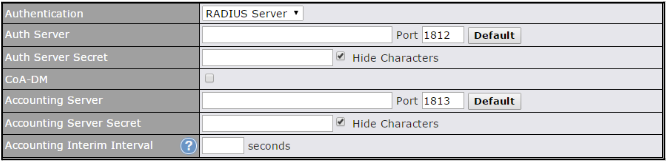
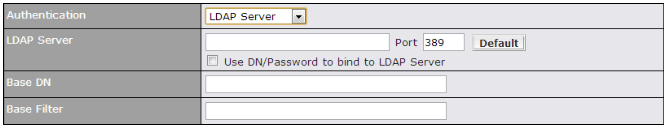
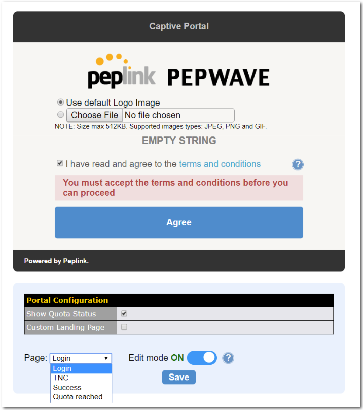
QoS#
User Groups#
LAN and PPTP clients can be categorized into three user groups – Manager, Staff, and Guest. This menu allows you to define rules and assign client IP addresses or subnets to a user group. You can apply different bandwidth and traffic prioritization policies on each user group in the Bandwidth Control and Application sections.
The table is automatically sorted, and the table order signifies the rules’ precedence. The smaller and more specific subnets are put towards the top of the table and have higher precedence; larger and less specific subnets are placed towards the bottom.
Click the Add button to define clients and their user group. Click the ![]() button to remove the defined rule.
button to remove the defined rule.
Two default rules are predefined and put at the bottom. They are All DHCP reservation clients and Everyone, and they cannot be removed. The All DHCP reservation client represents the LAN clients defined in the DHCP Reservation table on the LAN settings page. Everyone represents all clients that are not defined in any rule above. Click on a rule to change its group.
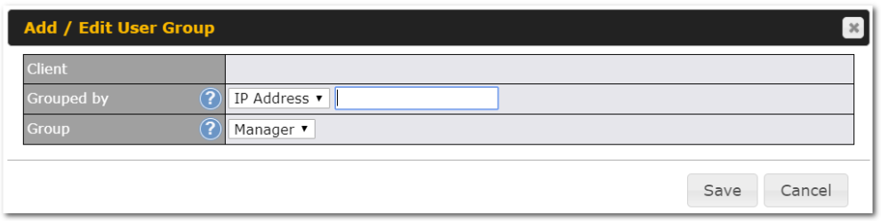
| Add / Edit User Group | |
| Subnet / IP Address | From the drop-down menu, choose whether you are going to define the client(s) by an IP Address or a Subnet. If IP Address is selected, enter a name defined in DHCP reservation table or a LAN client’s IP address. If Subnet is selected, enter a subnet address and specify its subnet mask. |
| Group | This field is to define which User Group the specified subnet / IP address belongs to. |
Once users have been assigned to a user group, their internet traffic will be restricted by rules defined for that particular group. Please refer to the following two sections for details.
Bandwidth Control#
This section is to define how much minimum bandwidth will be reserved to each user group when a WAN connection is in full load. When this feature is enabled, a slider with two indicators will be shown. You can move the indicators to adjust each group’s weighting. The lower part of the table shows the corresponding reserved download and uploads bandwidth value of each connection.
By default, 50% of bandwidth has been reserved for Manager, 30% for Staff, and 20% for Guest.
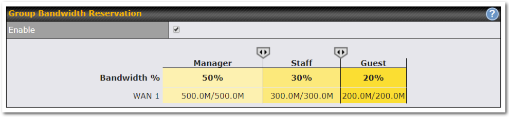
You can define a maximum download speed (over all WAN connections) and upload speed (for each WAN connection) that each individual Staff and Guest member can consume. No limit can be imposed on individual Managers. By default, download and upload bandwidth limits are set to unlimited (set as 0).
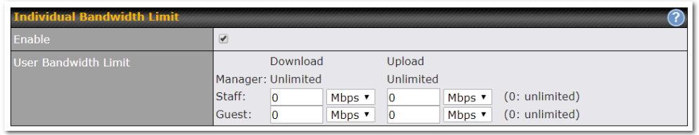
Application#
You can choose whether to apply the same prioritization settings to all user groups or customize the settings for each group.
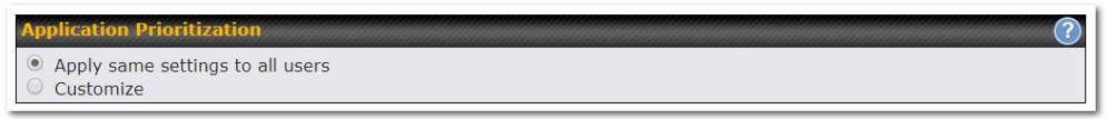
Three priority levels can be set for application prioritization: ↑High, ━ Normal, and ↓Low. The Peplink Balance can detect various application traffic types by inspecting the packet content. Select an application by choosing a supported application, or by defining a custom application manually. The priority preference of supported applications is placed at the top of the table. Custom applications are at the bottom.
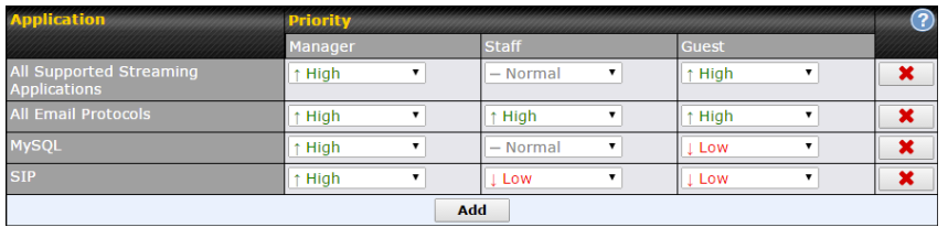
Prioritization for Custom Application
Click the Add button to define a custom application. Click the button in the Action column to delete the custom application in the corresponding row.
When Supported Applications is selected, the Peplink Balance will inspect network traffic and prioritize the selected applications. Alternatively, you can select Custom Applications and define the application by providing the protocol, scope, port number, and DSCP value.
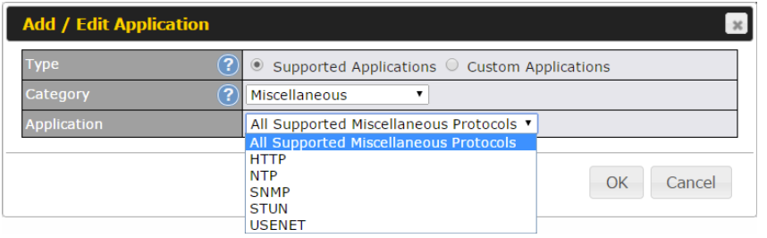
Category and Application availability will be different across different Peplink Balance models.
DSL/Cable Optimization
DSL/cable-based WAN connections have lower upload bandwidth and higher download bandwidth.
When a DSL/cable circuit’s uplink is congested, the download bandwidth will be affected. Users will not be able to download data at full speed until the uplink becomes less congested. DSL/Cable Optimization can relieve such an issue. When it is enabled, the download speed will become less affected by the upload traffic. By default, this feature is enabled.

Firewall#
A firewall is a mechanism that selectively filters data traffic between the WAN side (the Internet) and the LAN side of the network. It can protect the local network from potential hacker attacks, access to offensive websites, and/or other inappropriate uses.
The firewall functionality of Peplink Balance supports the selective filtering of data traffic in both directions:
Outbound (LAN to WAN)
Inbound (WAN to LAN)
Internal Network (VLAN to VLAN)
The firewall also supports the following functionality:
- Intrusion detection and DoS prevention
- Web blocking
With SpeedFusionTM enabled, the firewall rules also apply to VPN tunneled traffic. The Firewall function can be found at Network>Firewall
Access Rules#
The outbound firewall settings are located at Network>Firewall>Access Rules.
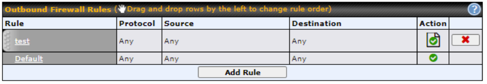
Click Add Rule to display the following screen:
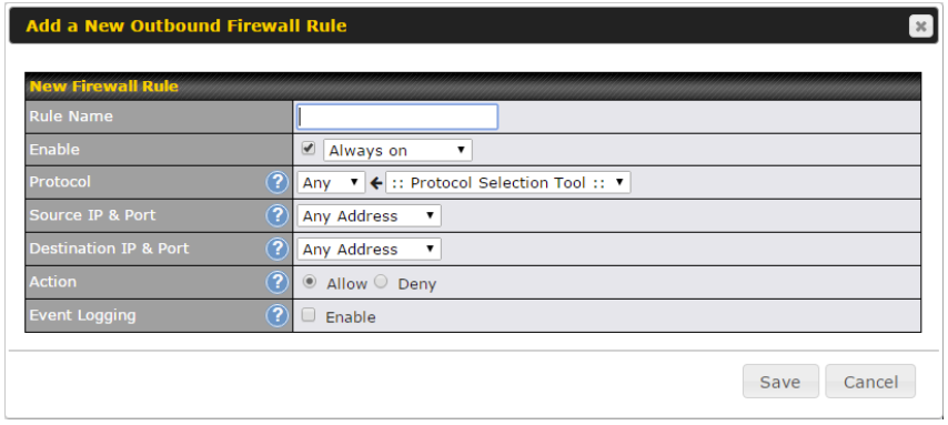
The inbound firewall settings are located at Network>Firewall>Access Rules.
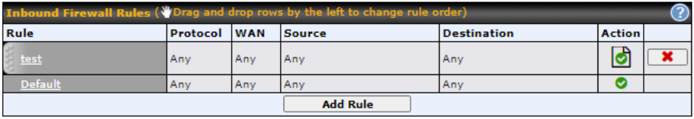
Click Add Rule to display the following window:
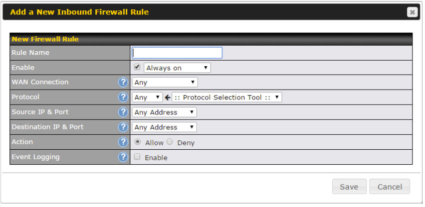
The Internal Network firewall settings are located at Network>Firewall>Access Rules.
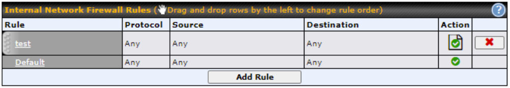
Click Add Rule to display the following window:
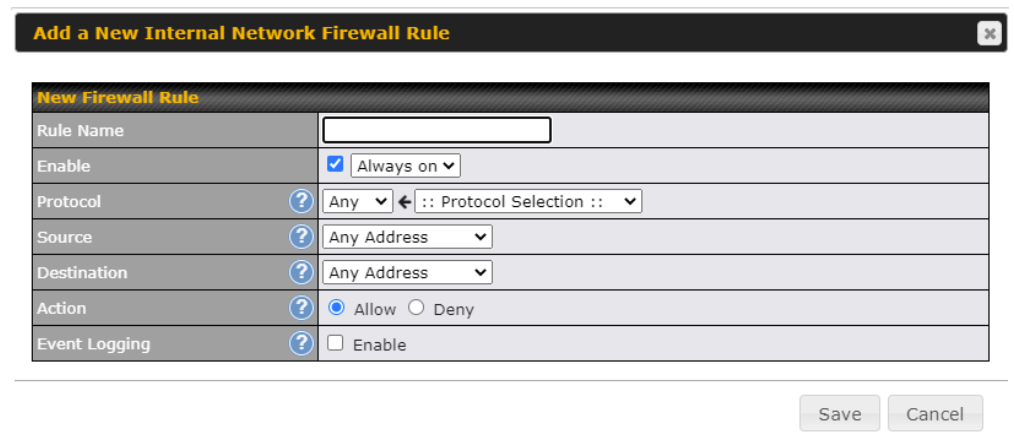
| Inbound / Outbound / Internal Network Firewall Settings | |
| Rule Name | This setting specifies a name for the firewall rule. |
| Enable | This setting specifies whether the firewall rule should take effect.
If the box is checked, the firewall rule takes effect. If the traffic matches the specified protocol/IP/port, actions will be taken by Peplink Balance based on the other parameters of the rule. If the box is not checked, the firewall rule does not take effect. The Peplink Balance will disregard the other parameters of the rule. Click the dropdown menu next to the checkbox to place this firewall rule on a time schedule. |
| WAN Connection (Inbound) | Select the WAN connection that this firewall rule should apply to. |
| Protocol | This setting specifies the protocol to be matched.
Via a drop-down menu, the following protocols can be specified:
Alternatively, the Protocol Selection Tool drop-down menu can be used to automatically fill in the protocol and port number of common Internet services (e.g., HTTP, HTTPS, etc.) After selecting an item from the Protocol Selection Tool drop-down menu, the protocol and port number remains manually modifiable. |
| Source and Port | This specifies the source IP address(es) and port number(s) to be matched for the firewall rule. A single address, or a network, can be specified as the Source IP & Port setting, as indicated with the following screenshots:
In addition, a single port, or a range of ports, can be specified for the Source settings. |
| Destination and Port | This specifies the destination IP address(es) and port number(s) to be matched for the firewall rule. A single address, or a network, can be specified as the Destination IP & Port setting, as indicated with the following screenshots:
In addition, a single port, or a range of ports, can be specified for the settings. |
| Action | This setting specifies the action to be taken by the router upon encountering traffic that matches the both of the following:
With the value of Allow for the Action setting, the matching traffic passes through the router (to be routed to the destination). If the value of the Action setting is set to Deny, the matching traffic does not pass through the router (and is discarded). |
| Event Logging | This setting specifies whether or not to log matched firewall events. The logged messages are shown on the page Status>Event Log. A sample message is as follows:
Aug 13 23:47:44 Denied CONN=Ethernet WAN SRC=20.3.2.1 DST=192.168.1.20 LEN=48 PROTO=TCP SPT=2260 DPT=80
|
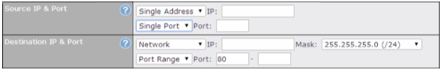

Click Save to store your changes. To create an additional firewall rule, click Add Rule and repeat the above steps.
To change a rule’s priority, simply drag and drop the rule:
- Hold the left mouse button on the rule.
- Move it to the desired position.
- Drop it by releasing the mouse button.
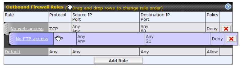
To remove a rule, click the ![]() button.
button.
Rules are matched from top to the bottom. If a connection matches any one of the upper rules, the matching process will stop. If none of the rules match the connection, the Default rule will be applied.
The Default rule is Allow for Outbound, Inbound and Internal Network access.
| Tip |
| If the default inbound rule is set to Allow for NAT-enabled WANs, no inbound Allow firewall rules will be required for inbound port forwarding and inbound NAT mapping rules. However, if the default inbound rule is set as Deny, a corresponding Allow firewall rule will be required. |
Intrusion Detection and DoS Prevention
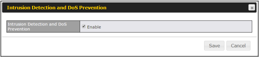
The Balance can detect and prevent intrusions and denial-of-service (DoS) attacks from the Internet. To turn on this feature, click ![]() , check the Enable check box for the Intrusion Detection and DoS Prevention, and press the Save button.
, check the Enable check box for the Intrusion Detection and DoS Prevention, and press the Save button.
When this feature is enabled, the Balance will detect and prevent the following kinds of intrusions and denial-of-service attacks.
- Port scan
- NMAP FIN/URG/PSH
- Xmas tree
- Another Xmas tree
- Null scan
- SYN/RST
- SYN/FIN
- SYN flood prevention
- Ping flood attack prevention
Content Blocking#
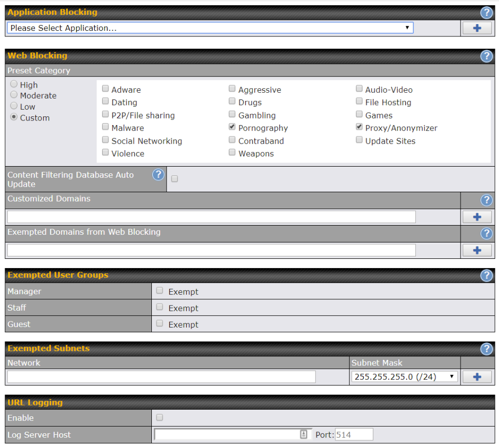
Application Blocking
Choose applications to be blocked from LAN/PPTP/PepVPN peer clients’ access, except for those on the Exempted User Groups or Exempted Subnets defined below.
Web Blocking
Defines website domain names to be blocked from LAN/PPTP/PepVPN peer clients’ access except for those on the Exempted User Groups or Exempted Subnets defined below.
If “foobar.com” is entered, any web site with a host name ending in foobar.com will be blocked, e.g. www.foobar.com, foobar.com, etc. However, “myfoobar.com” will not be blocked.
You may enter the wild card “.*” at the end of a domain name to block any web site with a host name having the domain name in the middle. If you enter “foobar.*”, then “www.foobar.com”, “www.foobar.co.jp”, or “foobar.co.uk” will be blocked. Placing the wild card in any other position is not supported.
The device will inspect and look for blocked domain names on all HTTP and HTTPS traffic.
Customized Domains
Enter an appropriate website address, and the Peplink Balance will block and disallow LAN/PPTP/SpeedFusionTM peer clients to access these websites. Exceptions can be added using the instructions in Sections 21.2.1.4 and 21.2.1.5.
You may enter the wild card “.*” at the end of a domain name to block any web site with a host name having the domain name in the middle. For example, If you enter “foobar.*,” then “www.foobar.com,” “www.foobar.co.jp,” or “foobar.co.uk” will be blocked. Placing the wild card in any other position is not supported.
The Peplink Balance will inspect and look for blocked domain names on all HTTP traffic. Secure web (HTTPS) traffic is not supported.
Exempted User Groups
Check and select pre-defined user group(s) who can be exempted from the access blocking rules. User groups can be defined at QoS>User Groups section. Please refer to Section 20.1 for details.
Exempted Subnets
With the subnet defined in the field, clients on the particular subnet(s) can be exempted from the access blocking rules.
URL Logging
Click enable, and then enter the ip address and port (if applicable) where your remote syslog server is located.
Routing Protocols#
OSPF & RIPv2#
The Peplink Balance supports OSPF and RIPv2 dynamic routing protocols. Click the Network tab from the top bar, and then click the Routing Protocols > OSPF & RIPv2 item on the sidebar to reach the following menu:
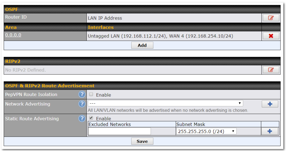
| OSPF | |
| Router ID | This field determines the ID of the router. By default, this is specified as the WAN IP address. If you want to specify your own ID, enter it into the Custom field. |
| Area | This is an overview of the OSPF areas that you have defined. Clicking on the name under Area allows you to configure the connection. To define a new area, click Add. To delete an existing area, click on the |
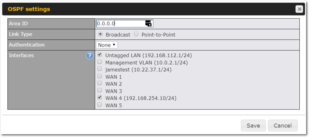
| OSPF Settings | |
| Area ID | Assign a name to be applied to this group. Machines linked to this group will send and receive related OSPF packets, while unlinked machines will ignore them. |
| Link Type | Choose the type of network that this area will use. |
| Authentication | If an authentication method is used, select one from this drop-down menu. Available options are MD5 and Text. Authentication key(s) may be input next to the drop-down menu after selecting an authentication method. |
| Interfaces | Select the interface(s) that this area will use to listen to and deliver OSPF packets. |
To access RIPv2 settings, click on ![]() .
.
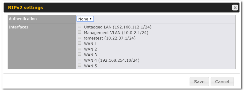
| RIPv2 Settings | |
| Authentication | If an authentication method is used, select one from this drop-down menu. Available options are MD5 and Text. Authentication key(s) may be input next to the drop-down menu after selecting an authentication method. |
| Interfaces | Select the interface(s) that this area will use to listen to and deliver RIPv2 packets. |
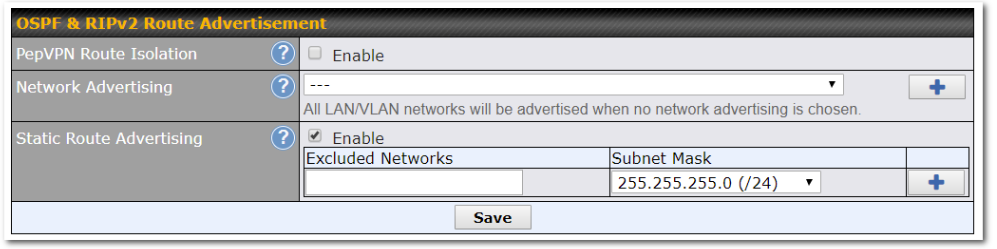
| OSPF & RIPv2 Route Advertisement | |
| PepVPN Route Isolation | Isolate PepVPN peers from each other. Received PepVPN routes will not be forwarded to other PepVPN peers to reduce bandwidth consumption.. |
| Network Advertising | Networks to be advertised over OSPF & RIPv2. If no network is selected, all LAN / VLAN networks will be advertised by default. |
| Static Route Advertising | Enabling OSPF & RIPv2 Route Advertising allows it to advertise LAN static routes over OSPF & RIPv2. Static routes on the Excluded Networks table will not be advertised. |
BGP#
Click the Network tab along the top bar, and then click the BGP item on the sidebar to configure BGP.
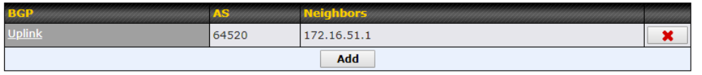
Click the “x” to delete a BGP profile.
Click “Add” to create a new BGP profile.
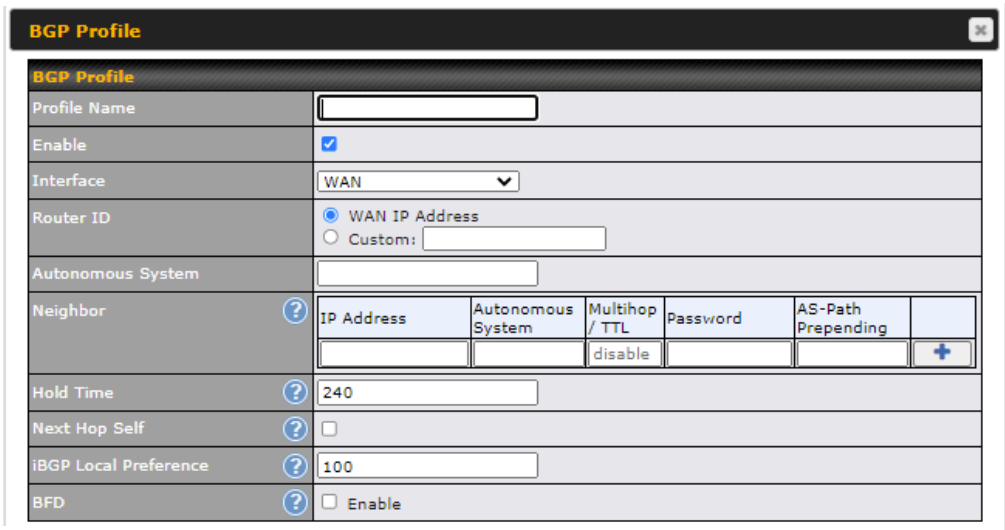
| BGP | |
| Name | This field specifies the name that represents this profile. |
| Enable | When this box is checked, this BGP profile will be enabled. If it is left unchecked, it will be disabled. |
| Interface | The interface in which the BGP neighbor is located. |
| Autonomous System | The Autonomous System Number (ASN) assigned to this profile. |
| Neighbor | BGP Neighbors and their details. |
| IP address | The IP address of the Neighbor. |
| Autonomous System | The Neighbor’s ASN. |
| Multihop/TTL | This field determines the Time-to-live (TTL) of BGP packets. Leave this field blank if the BGP neighbor is directly connected, otherwise you must specify a TTL value. This option should be used if the configured Neighbor’s IP address does not match the selected Interface’s network subnets. The TTL value must be between 2 to 255. |
| Password | (Optional) Assign a password for MD5 authentication of BGP sessions. |
| AS-Path Prepending: | AS path to be prepended to the routes received from this Neighbor. Values must be ASN and separated by commas. For example: inputting “64530,64531” will prepend “64530, 64531” to received routes. |
| Hold Time | Wait time in seconds for a keepalive message from a Neighbor before considering the BGP connection as stalled.
The value must be either 0 (infinite hold time) or between 3 and 65535 inclusively. Default: 240 |
| Next Hop Self | Enable this option to advertise your own source address as the next hop when propagating routes. |
| iBGP Local Preference | This is the metric advertised to iBGP Neighbors to indicate the preference for external routes. The value must be between 0 to 4294967295 inclusively.
Default: 100 |
| BFD | Enable this option to add Bidirectional Forwarding Detection for path failure. All directly connected Neighbors that use the same physical interface share the same BFD settings. All mulithop Neighbors share the same multihop BFD settings. You can configure BFD settings in the BGP profile listing page after this option is enabled. |
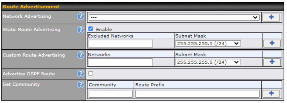
| Route Advertisement | |
| Network Advertising | Select the Networks that will be advertised to the BGP Neighbor. |
| Static Route Advertising | Enable this option to advertise static LAN routes. Static routes that match the Excluded Networks table will not be advertised. |
| Custom Route Advertising | Additional routes to be advertised to the BGP Neighbor. |
| Advertise OSPF Route | When this box is checked, every learnt OSPF route will be advertised. |
| Set Community | Assign a prefix to a Community
Community: Two numbers in new-format. e.g. 65000:21344 Well-known communities: no-export 65535:65281 no-advertise 65535:65282 no-export-subconfed 65535:65283 no-peer 65535:65284 Route Prefix: Comma separated networks. e.g. 172.168.1.0/24,192.168.1.0/28 |
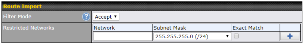
| Route Import Settings | |
| Filter Mode | This field allows for the selection of the filter mode for route import.
None: All BGP routes will be accepted. Accept: Routes in “Restricted Networks” will be accepted, routes not in the list will be rejected. Reject: Routes in “Restricted Networks” will be rejected, routes not in the list will be accepted. |
| Restricted Networks | This field specifies the network(s) in the “route import” entry.
Exact Match: When this box is checked, only routes with the same Network and Subnet Mask will be filtered. |
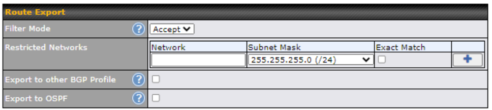
| Filter Mode | This field allows for the selection of the filter mode for route export.
None: All BGP routes will be accepted. Accept: Routes in “Restricted Networks” will be accepted, routes not in the list will be rejected. Reject: Routes in “Restricted Networks” will be rejected, routes not in the list will be accepted. |
| Restricted Networks | This field specifies the network(s) in the “route export” entry.
Exact Match: When this box is checked, only routes with the same Network and Subnet Mask will be filtered. |
| Export to other BGP Profile | When this box is checked, routes learnt from this BGP profile will be exported to other BGP profiles. |
| Export to OSPF | When this box is checked, routes learnt from this BGP profile will be exported to the OSPF routing protocol. |
Remote User Access#
A remote-access VPN connection allows an individual user to connect to a private business network from a remote location using a laptop or desktop computer connected to the Internet. Networks routed by a Peplink router can be remotely accessed via OpenVPN, L2TP with IPsec or PPTP. To configure this feature, navigate to Network > Remote User Access and choose the required VPN type.
L2TP with IPsec#
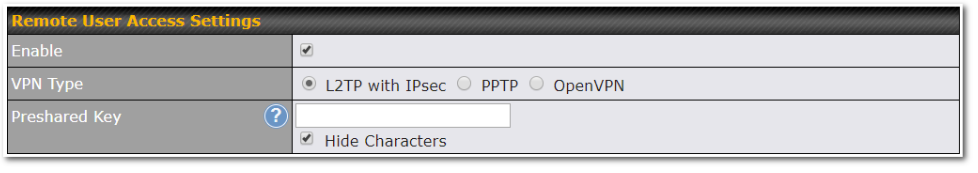
| L2TP with IPsec Remote User Access Settings | |
| Pre-shared Key | Enter your pre shared key in the text field. Please note that remote devices will need this preshared key to access the Balance. |
| Listen On | This setting is for specifying the WAN IP addresses that allow remote user access. |
| Disable Weak Ciphers | Click the When checked, weak ciphers such as 3DES will be disabled. |
Continue to configure the authentication method.
OpenVPN#
You can input the ‘Connection Security Refresh‘ and enable the ‘Authentication Token Lifetime.’

After enabling ‘Authentication Token Lifetime,’ you are able to enter the value as well.

| Connection Security Refresh | Refresh token lifetime. |
| Authentication Token Lifetime | Access token lifetime. |
PPTP#
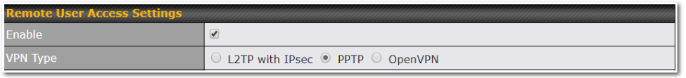
No additional configuration required.
The Point-to-Point Tunneling Protocol (PPTP) is an obsolete method for implementing virtual private networks. PPTP has many well known security issues
Continue to configure authentication methods.
Authentication Methods#
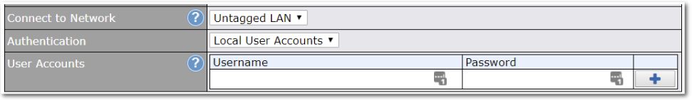
| Authentication Method | |
| Connect to Network | Select the VLAN network for remote users to enable remote user access on. |
| Authentication | Determine the method of authenticating remote users |
User accounts:
This setting allows you to define the Remote User Accounts.
Click Add to input username and password to create an account. After adding the user accounts, you can click on a username to edit the account password.
Note:
The username must contain lowercase letters, numerics, underscore(_), dash(-), at sign(@), and period(.) only.
The password must be between 8 and 12 characters long.
LDAP Server:
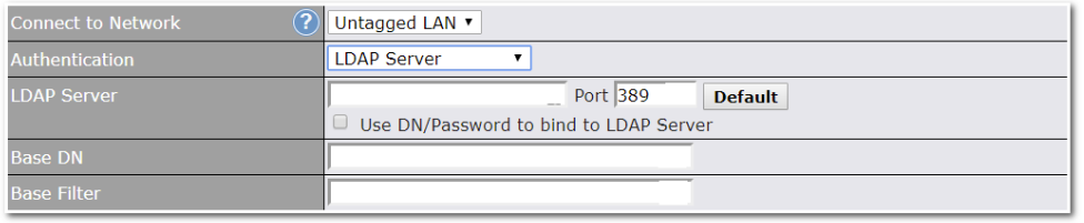
Enter the matching LDAP server details to allow for LDAP server authentication.
Radius Server:
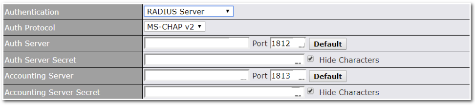
Enter the matching Radius server details to allow for Radius server authentication.
Active Directory:
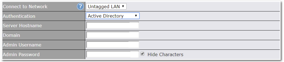
Enter the matching Active Directory details to allow for Active Directory server authentication.
Misc. Settings#
High Availability#
Peplink Balance supports high availability (HA) configurations via an open standard virtual router redundancy protocol (VRRP, RFC 3768).
In an HA configuration, two same-model Peplink Balance units provide redundancy and failover in a master-slave arrangement. In the event that the master unit is down, the slave unit becomes active.
High availability will be disabled automatically where there is a drop-in connection configured on a LAN bypass port.
The following diagram illustrates an HA configuration with two Peplink Balance units and two Internet connections:
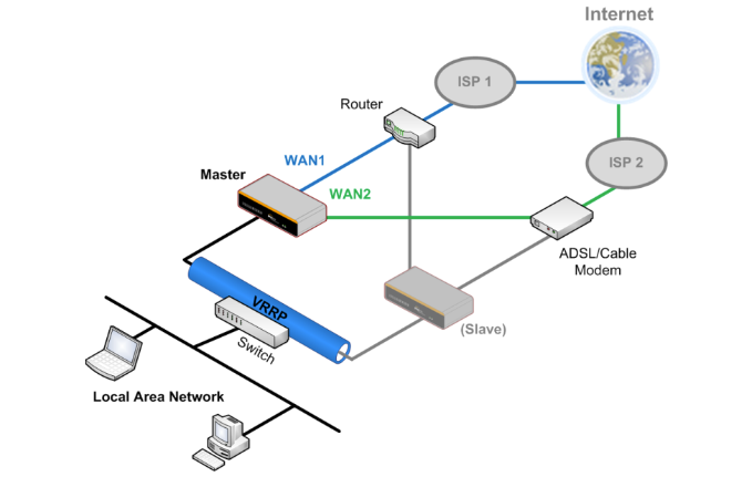
In the diagram, the WAN ports of each Peplink Balance unit connect to the router and to the modem. Both Peplink Balance units connect to the same LAN switch via a LAN port.
An elaboration on the technical details of the implementation of virtual router redundancy protocol (VRRP, RFC 3768) by the Balance follows:
- In an HA configuration, the two Peplink Balance units communicate with each other using VRRP over the LAN.
- The two Peplink Balance units broadcast heartbeat signals to the LAN at a frequency of one heartbeat signal per second.
- In the event that no heartbeat signal from the master Peplink Balance unit is received in 3 seconds (or longer) since the last heartbeat signal, the slave Peplink Balance unit becomes active.
- The slave Peplink Balance unit initiates the WAN connections and binds to a previously configured LAN IP address.
- At a subsequent point when the master Peplink Balance unit recovers, it will once again become active.
You can configure high availability at Network>Misc. Settings>High Availability.
| Interface for Master Router | Interface for Slave Router |
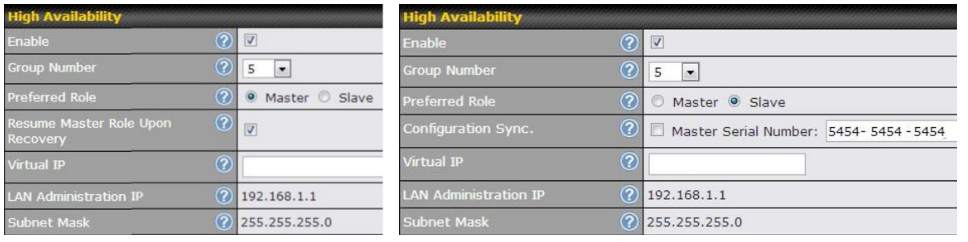
| High Availability | |
| Enable | Checking this box specifies that the Peplink Balance unit is part of a high availability configuration. |
| Group Number | This number identifies a pair of Peplink Balance units operating in a high availability configuration. The two Peplink Balance units in the pair must have the same Group Number value. |
| Preferred Role | This setting specifies whether the Peplink Balance unit operates in master or slave mode. Click the corresponding radio button to set the role of the unit. One of the units in the pair must be configured as the master, and the other unit must be configured as the slave. |
| Resume Master Role Upon Recovery | This option is displayed when Master mode is selected in Preferred Role. If this option is enabled, once the device has recovered from an outage, it will take over and resume its Master role from the slave unit. |
| Configuration Sync. | This option is displayed when Slave mode is selected in Preferred Role. If this option is enabled and the Master Serial Number entered matches with the actual master unit’s, the master unit will automatically transfer the configuration to this unit. Please make sure the LAN IP Address and the Subnet Mask fields are set correctly in the LAN settings page. You can refer to the Event Log for the configuration synchronization status. |
| Master Serial Number | If Configuration Sync. is checked, the serial number of the master unit is required here for the feature to work properly. |
| Virtual IP | The HA pair must share the same Virtual IP. The Virtual IP and the LAN Administration IP must be under the same network. |
| LAN Administration IP | This setting specifies a LAN IP address to be used for accessing administration functionality. This address should be unique within the LAN. |
| Subnet Mask | This setting specifies the subnet mask of the LAN. |
| Important Note |
| For Balance routers in NAT mode, the virtual IP (VIP) should be set as the default gateway for all hosts sitting on the LAN segment. For example, a firewall sitting behind the Balance should set its default gateway as the virtual IP instead of the IP of the master Balance.
Please note that the drop-in WAN cannot be configured as a LAN bypass port while it is configured for high availability. |
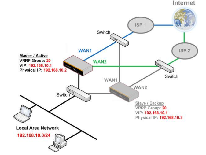
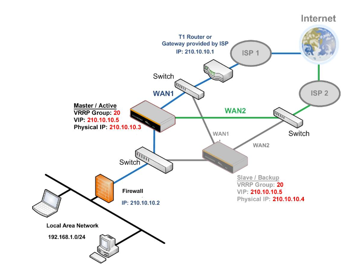
Certificate Manager#
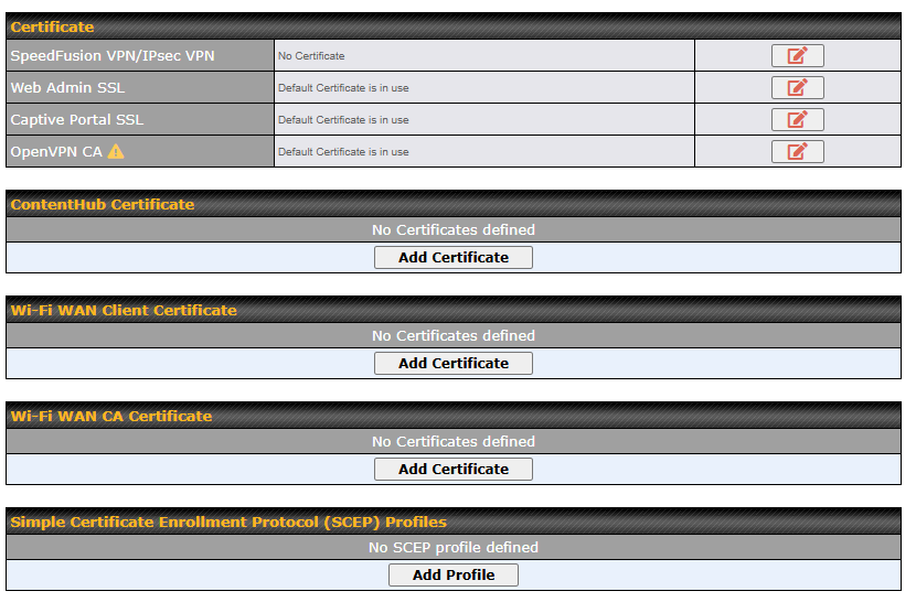
This section allows you to assign certificates for local VPN, OpenVPN, Captive Portal, MediaFast, ContentHub, Wi-Fi WAN (Client and CA), and web admin SSL for extra security.
Read the following knowledgebase article for full instructions on creating and importing a self-signed certificate: https://forum.peplink.com/t/how-to-create-a-self-signed-certificate-and-import-it-to-a-peplink-product/
Simple Certificate Enrollment Protocol (SCEP) profiles are used to issue certificates automatically from the SCEP server.
| General Settings | ||
| Name | Profile Name | |
| Issuer | ||
| Enrollment Server URL | SCEP endpoint to obtain an enrollment certificate. For example, enter something like https://ndes.contoso.com/certsrv/mscep/mscep.dll. | |
| Password | SCEP server password. | |
| Certificate Renewal Interval | Days to renew/obtain an enrollment certificate. | |
| Certificate Subject | ||
| Common Name (CN) | Hostname for certificate is issued. (Required) | |
| Organization Unit (OU) | Department, section, trademark (Optional) | |
| Organization (O) | Organization name for certificated is issued. (Required) | |
| Locality (L) | City name (Optional) | |
| State (S) | State for certificated is issued. (Required) | |
| Country (C) | Country Code in two letter (eg. US) (Required) | |
| E-mail (E) | Email address (Optional) | |
| Configured Certificate | ||
| Certificates |
|
Option to choose which service(s) to apply. |
Service Forwarding#
Service forwarding settings are located at Network>Misc. Settings>Service Forwarding.
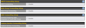
| Service Forwarding | |
| SMTP Forwarding | When this option is enabled, all outgoing SMTP connections destined for any host at TCP port 25 will be intercepted. These connections will be redirected to a specified SMTP server and port number. SMTP server settings for each WAN can be specified after selecting Enable. |
| Web Proxy Forwarding | When this option is enabled, all outgoing connections destined for the proxy server specified in Web Proxy Interception Settings will be intercepted. These connections will be redirected to a specified web proxy server and port number. Web proxy interception settings and proxy server settings for each WAN can be specified after selecting Enable. |
| DNS Forwarding | When this option is enabled, all outgoing DNS lookups will be intercepted and redirected to the built-in DNS name server. If any LAN device is using the DNS name servers of a WAN connection, you may want to enable this option to enhance the DNS availability without modifying the DNS server setting of the clients. The built-in DNS name server will distribute DNS lookups to corresponding DNS servers of all available WAN connections. In this case, DNS service will not be interrupted, even if any WAN connection is down. |
| Custom Service Forwarding | When custom service forwarding is enabled, outgoing traffic with the specified TCP port will be forwarded to a local or remote server by defining its IP address and port number. |
SMTP Forwarding
Some ISPs require their users to send e-mails via the ISP’s SMTP server. All outgoing SMTP connections are blocked except those connecting to the ISP’s. The Peplink Balance supports the interception and redirection of all outgoing SMTP connections (destined for TCP port 25) via a WAN connection to the WAN’s corresponding SMTP server.
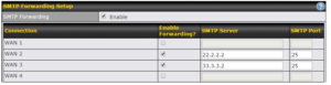
To enable the feature, select Enable under SMTP Forwarding Setup. Check Enable Forwarding for the WAN connection(s) that needs forwarding. Under SMTP Server, enter the ISP’s e-mail server host name or IP address. Under SMTP Port, enter the TCP port number for each WAN.
The Peplink Balance will intercept SMTP connections. Choose a WAN port according to the outbound policy, and then forward the connection to the SMTP server, if the chosen WAN has enabled forwarding. If the forwarding is disabled for a WAN connection, SMTP connections for the WAN will be simply be forwarded to the connection’s original destination.
| Note |
| If you want to route all SMTP connections only to particular WAN connection(s), you should create a custom rule in outbound policy (see Section 16.1). |
Web Proxy Forwarding
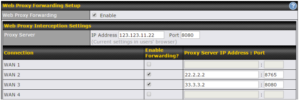
When this feature is enabled, the Peplink Balance will intercept all outgoing connections destined for the proxy server specified in Web Proxy Server Interception Settings. Then it will choose a WAN connection according to the outbound policy and forward the connection to the specified web proxy server and port number. Redirected server settings for each WAN can be set here. If forwarding is disabled for a WAN, then web proxy connections for that WAN will simply be forwarded to the connection’s original destination.
DNS Forwarding

When DNS forwarding is enabled, all clients’ outgoing DNS requests will also be intercepted and forwarded to the built-in DNS proxy server.
Custom Service Forwarding.
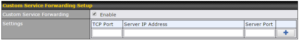
After clicking the enable checkbox, enter your TCP port for traffic heading to the router, and then specify the IP Address and Port of the server you wish to forward to the service to.
Service Passthrough#
Service passthrough settings can be found at Network>Misc. Settings>Service Passthrough.
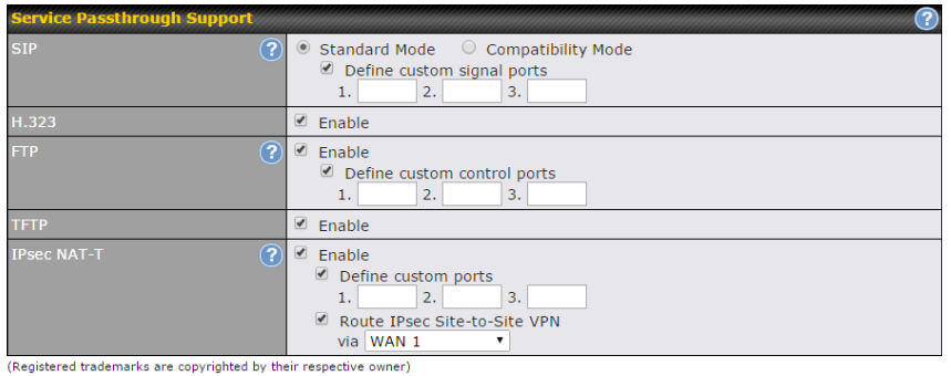
Some Internet services need to be specially handled in a multi-WAN environment. The Peplink Balance can handle these services such that Internet applications do not notice it is behind a multi-WAN router. Settings for service passthrough support are available here.
| Service Passthrough Support | |
| SIP | Session initiation protocol, aka SIP, is a voice-over-IP protocol. The Peplink Balance can act as a SIP application layer gateway (ALG) which binds connections for the same SIP session to the same WAN connection and translate IP address in the SIP packets correctly in NAT mode. Such passthrough support is always enabled and there are two modes for selection: Standard Mode and Compatibility Mode.
If your SIP server’s signal port number is non-standard, you can check the box Define custom signal ports and input the port numbers to the text boxes. |
| H.323 | With this option enabled, protocols that provide audio-visual communication sessions will be defined on any packet network and passthrough the Balance. |
| FTP | FTP sessions consist of two TCP connections; one for control and one for data. In a multi-WAN situation, they must be routed to the same WAN connection. Otherwise, problems will arise in transferring files. By default, the Peplink Balance monitors TCP control connections on port 21 for any FTP connections and binds TCP connections of the same FTP session to the same WAN.
If you have an FTP server listening on a port number other than 21, you can check Define custom control ports and enter the port numbers in the text boxes. |
| TFTP | The Peplink Balance monitors outgoing TFTP connections and routes any incoming TFTP data packets back to the client. Select Enable if you want to enable TFTP passthrough support. |
| IPsec NAT-T | This field is for enabling the support of IPsec NAT-T passthrough. UDP ports 500, 4500, and 10000 are monitored by default.
You may add more custom data ports that your IPsec system uses by checking Define custom ports. If the VPN contains IPsec site-to-site VPN traffic, check Route IPsec Site-to-Site VPN and choose the WAN connection to route the traffic to. |
GPS#
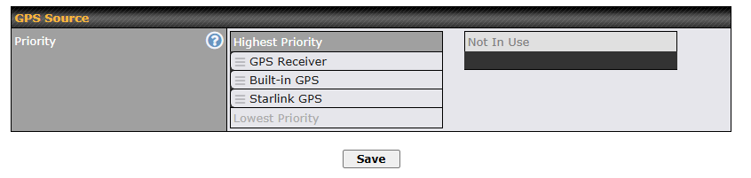
This settings is to specific the priority of the GPS source to be used for receiving GPS data. The device will always use the highest priority GPS source to receive GPS data. A lower priority GPS source will only be used when all higher priority GPS source data is invalid or unavailable. GPS source type will be shows on the Dashboard map.
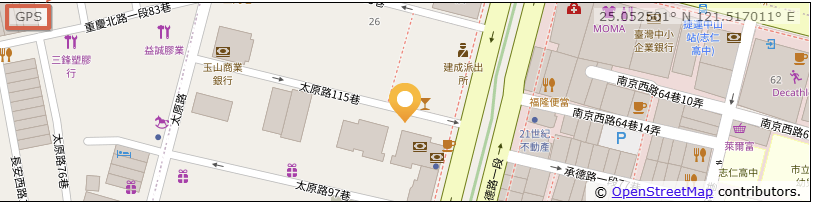
GPS Forwarding#
Using the GPS forwarding feature, some Peplink routers can automatically send GPS reports to a specified server. To set up GPS forwarding, navigate to Advanced > GPS Forwarding.
*This features only on devices which supports GPS. To check with device support GPS, kindly refer to our “Compare Router models” table.
https://www.peplink.com/compare/routers/
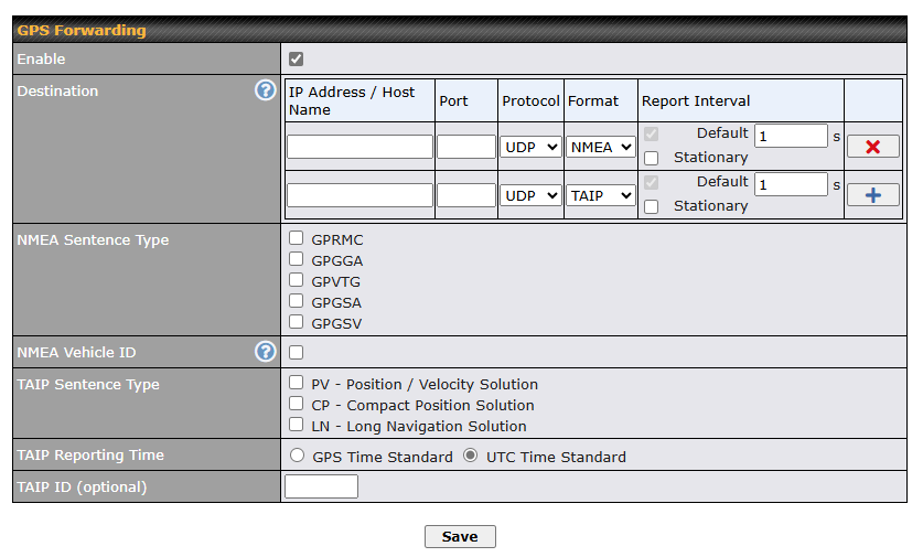
| GPS Forwarding | |
| Enable | Check this box to turn on GPS forwarding. |
| Server | Enter the name/IP address of the server that will receive GPS data. Also specify a port number, protocol (UDP or TCP), Format (NMEA or TAIP) and a report interval. Click |
| NMEA Sentence Type | If you’ve chosen to send GPS reports in NMEA format, select one or more sentence types for sending the data (GPRMC, GPGGA, GPVTG, GPGSA, and GPGSV). |
| TAIP Reporting Time | Option to select GPS Time Standard or UTC Time Standard. |
| Vehicle ID | The vehicle ID will be appended in the last field of the NMEA sentence. Note that the NMEA sentence will become customized and non-standard. |
| TAIP Sentence Type/TAIP ID (optional) | If you’ve chosen to send GPS reports in TAIP format, select one or more sentence types for sending the data (PV—Position / Velocity Solution and CP—Compact Velocity Solution). You can also optionally include an ID number in the TAIP ID field. |
GPS Receiver#
* This features only on devices which supports GPS. To check with device support GPS, kindly refer to our “Compare Router models” table.
https://www.peplink.com/compare/routers/
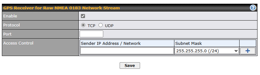
| GPS Receiver for Raw NMEA 0183 Network Stream | |
| Enable | Check this box to turn on GPS forwarding. |
| Protocol | Select protocol TCP or UDP |
| Port | Specific port number. |
| Access Control | Enter the IP address / Network of the sender. Click |
NTP Server#
Peplink routers can now serve as a local NTP server. Upon start up, it is now able to provide connected devices with the accurate time, precise UTC from either an external NTP server or via GPS and ensuring that connected devices always receive the correct time.
NTP Server setting can be found via: Advanced => Misc. Settings => NTP Server
(For Balance 20X | Firmware 8.4.1)
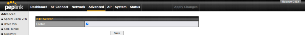
(For Balance 710 | Fireware 8.4.0)
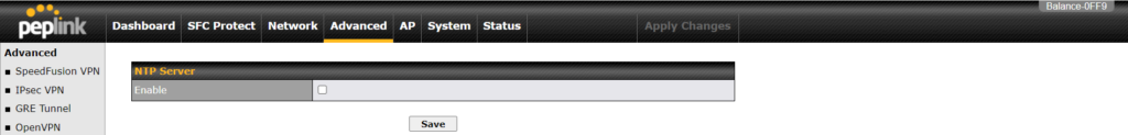
Time Settings can be found at System>Time>Time Settings
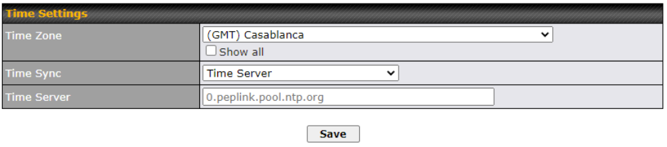
Grouped Networks#
Advanced > Grouped Networks allows you to configure destination networks in a grouped format.

Select Add Group to create a new group with single IP addresses, subnets from different VLANs, or domain names.

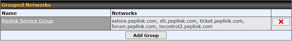
The created network groups can be used in outbound policies and firewall rules.
Remote SIM Management#
Remote SIM management is accessible via Network > Misc Settings > Remote SIM Management. By default, this feature is disabled.
Please note that a limited number of Pepwave routers support the SIM Injector, may refer to the link: https://www.peplink.com/products/sim-injector/ or Appendix C for more details on FusionSIM Manual.

Remote SIM Host Settings
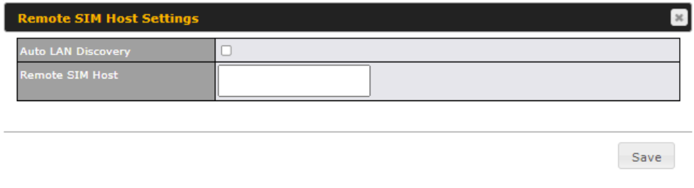
| Remote SIM Host Settings | |
| Active LAN Discovery | Check this box to enable Auto LAN discovery of the remote SIM server. |
| Remote SIM Host | Enter the public IP address of the SIM Injector. If you enter IP addresses here, it is not necessary to tick the “Auto LAN Discovery” box above. |
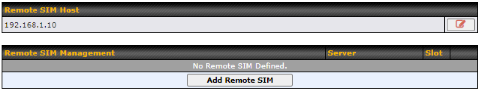
You may define the Remote SIM information by clicking the “Add Remote SIM”. Here, you can enable Data Roaming and custom APN for your SIM cards.
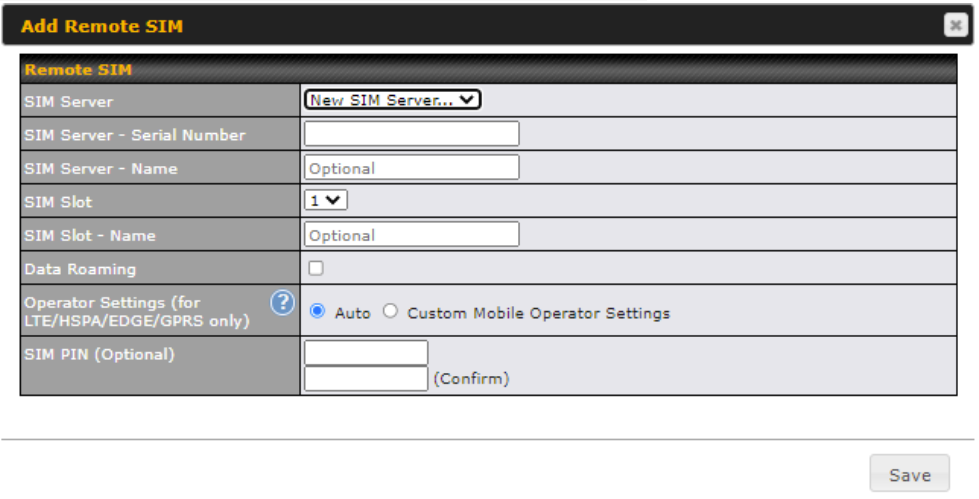
| Add Remote SIM Settings | |
| SIM Server | Add a new SIM Server |
| SIM Server – Serial Number | Enter the serial number of SIM Server |
| SIM Server – Name | This optional field allows you define a name for the SIM Server |
| SIM Slot | Click the drop-down menu and choose which SIM slot you want to connect. |
| SIM Slot – Name | This optional field allows you define a name for the SIM slot. |
| Data Roaming | Enables data roaming on this particular SIM card. |
| Operator Settings (for LTE//HSPA/EDGE/GPRS Only) | This setting allows you to configure the APN settings of your connection. If Auto is selected, the mobile operator should be detected automatically. The connected device will be configured and connection will be made automatically. If there is any difficulty in making a connection, you may select Custom to enter your carrier’s APN, Username and Password settings manually. The correct values can be obtained from your carrier. The default and recommended setting is Auto. |
SIM Toolkit#
The SIM Toolkit can be found via Networks > Misc Settings > SIM Toolkit.This supports two functionalities, USSD and SMS.
USSD
Unstructured Supplementary Service Data (USSD) is a protocol used by mobile phones to communicate with their service provider’s computers. One of the most common uses is to query the available balance.
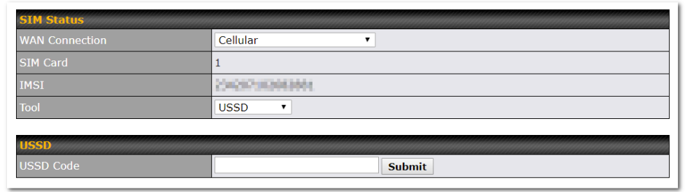
Enter your USSD code under the USSD Code text field and click Submit.
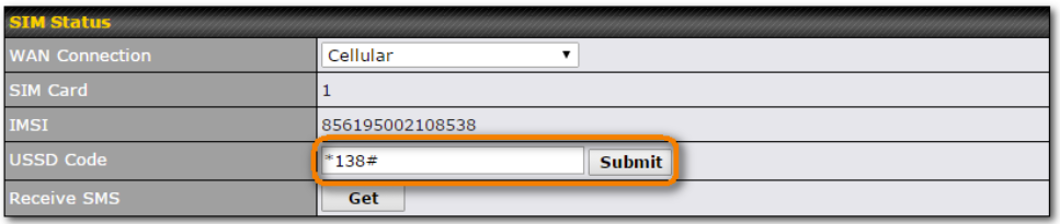
You will receive a confirmation. To check the SMS response, click Get.
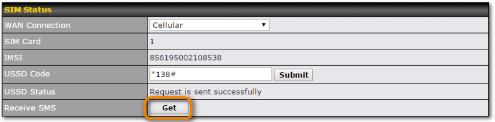
After a few minutes you will receive a response to your USSD code
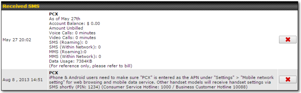
SMS
The SMS option allows you to read SMS (text) messages that have been sent to the SIM in your Peplink router.
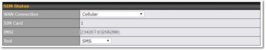
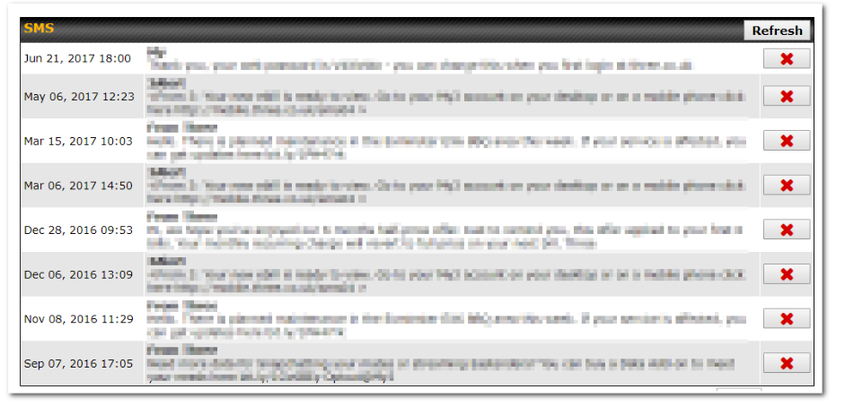
Ch13. AP Tab#
AP#
AP Controller#
Clicking on the AP tab will default to this menu, where you can view basic AP management options:
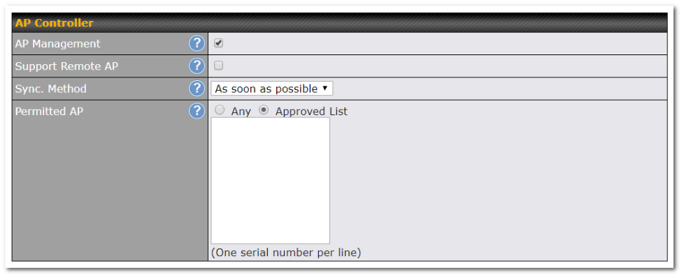
| AP Controller | |
| AP Management | The AP controller for managing Pepwave APs can be enabled by checking this box. When this option is enabled, the AP controller will wait for management connections originating from APs over the LAN on TCP and UDP port 11753. It will also wait for captive portal connections on TCP port 443. An extended DHCP option, CAPWAP Access Controller addresses (field 138), will be added to the DHCP server. A local DNS record, AP Controller, will be added to the local DNS proxy. |
| Support Remote AP | The AP controller supports remote management of Pepwave APs. When this option is enabled, the AP controller will wait for management connections originating from remote APs over the WAN on TCP and UDP port 11753. It will also wait for captive portal connections on TCP port 443.
The DHCP server and/or local DNS server of the remote AP’s network should be configured in the DNS Proxy Settings menu under Network>LAN. The procedure is as follows:
|
| Sync. Method | Select the required option to synchronize the managed AP’s. Options are:
|
| Permitted AP | Access points to manage can be specified here. If Any is selected, the AP controller will manage any AP that reports to it. If Approved List is selected, only APs with serial numbers listed in the provided text box will be managed. |
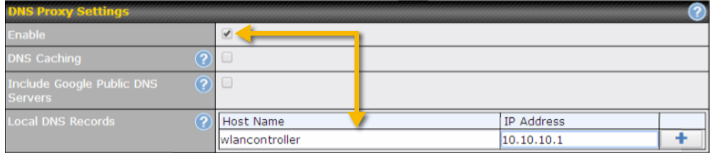
Wireless SSID#

Current SSID information appears in the SSID section. To edit an existing SSID, click its name in the list. To add a new SSID, click Add. Note that the following settings vary by model.
The below settings show a new SSID window with Advanced Settings enabled (these are available by selecting the question mark in the top right corner).
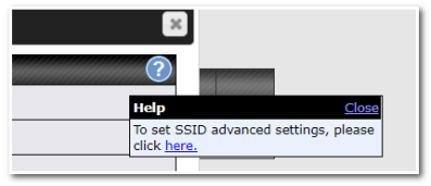
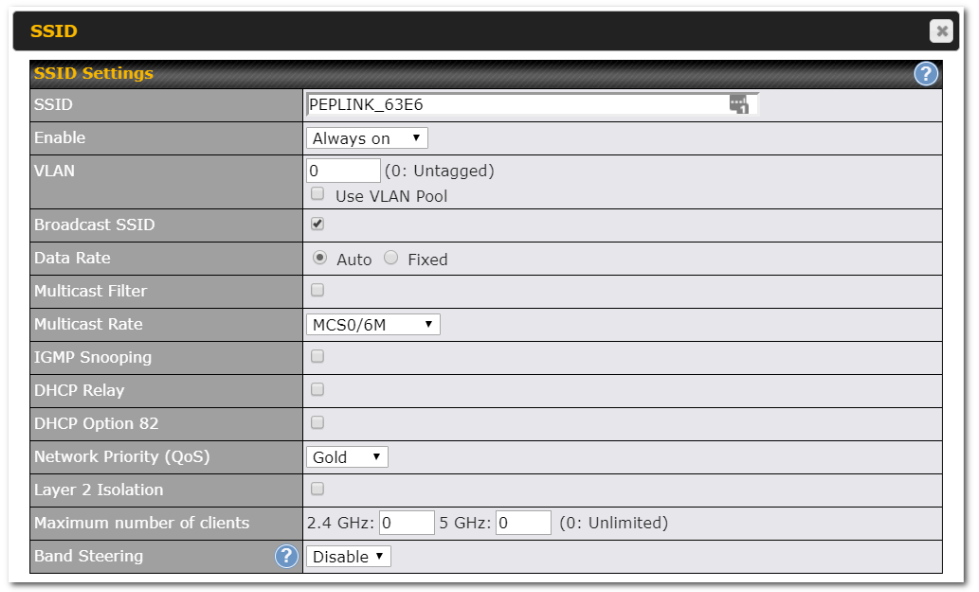
| SSID Settings | |
| SSID | This setting specifies the SSID of the virtual AP to be scanned by Wi-Fi clients. |
| Enable | Click the drop-down menu to apply a time schedule to this interface |
| VLAN | This setting specifies the VLAN ID to be tagged on all outgoing packets generated from this wireless network (i.e., packets that travel from the Wi-Fi segment through the Pepwave AP One unit to the Ethernet segment via the LAN port). The default value of this setting is 0, which means VLAN tagging is disabled (instead of tagged with zero). Use of a VLAN pool is enabled by selecting the checkbox. |
| Broadcast SSID | This setting specifies whether or not Wi-Fi clients can scan the SSID of this wireless network. Broadcast SSID is enabled by default. |
| Data Rate^ | Select Auto to allow the Pepwave router to set the data rate automatically, or select Fixed and choose a rate from the displayed drop-down menu. |
| Multicast Filter^ | This setting enables the filtering of multicast network traffic to the wireless SSID. |
| Multicast Rate^ | This setting specifies the transmit rate to be used for sending multicast network traffic. The selected Protocol and Channel Bonding settings will affect the rate options and values available here. |
| IGMP Snooping^ | To allow the Pepwave router to listen to internet group management protocol (IGMP) network traffic, select this option. |
| DHCP Relay | Put the address of the DHCP server in this field.. DHCP requests will be relayed to this DHCP server |
| DHCP Option 82^ | If you use a distributed DHCP server/relay environment, you can enable this option to provide additional information on the manner in which clients are physically connected to the network. |
| Layer 2 Isolation^ | Layer 2 refers to the second layer in the ISO Open System Interconnect model.
When this option is enabled, clients on the same VLAN, SSID, or subnet are isolated to that VLAN, SSID, or subnet, which can enhance security. Traffic is passed to upper communication layer(s). By default, the setting is disabled. |
| Maximum Number of Clients | Indicate the maximum number of clients that should be able to connect to each frequency. |
| Band Steering | To reduce 2.4 GHz band overcrowding, AP with band steering steers clients capable of 5 GHz operation to 5 GHz frequency.
Choose between: Force – Clients capable of 5 GHz operation are only offered with 5 GHz frequency. Prefer – Clients capable of 5 GHz operation are encouraged to associate with 5 GHz frequency. If the clients insist to attempt on 2.4 GHz frequency, 2.4 GHz frequency will be offered. Disable – Default |
^ Advanced feature. Click the ![]() button on the top right-hand corner to activate.
button on the top right-hand corner to activate.

| Security Settings | |
| Security Policy | This setting configures the wireless authentication and encryption methods. Available options are:
To allow any Wi-Fi client to access your AP without authentication, select Open (No Encryption). Details of each available authentication method follow. |

| Enhanced Open (OWE) | |
| Transition Mode | With the option enabled, legacy clients will be able to connect in Open mode. With the option disabled, legacy clients will not be able to connect. OWE-supported clients will always connect in OWE mode. |
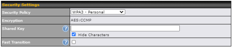
| WPA3 – Personal | |
| Shared Key | Enter a passphrase of between 8 and 63 alphanumeric characters to create a passphrase used for data encryption and authentication. Click Hide / Show Characters to toggle visibility. |
| Fast Transition | Fast Transition
[802.11r] When this option is ticked, the transition process for a mobile client is improved as it moves between access points. |

| WPA3 – Enterprise | |
| 802.1X Version | Choose v1 or v2 of the 802.1x EAPOL. When v1 is selected, both v1 and v2 clients can associate with the access point. When v2 is selected, only v2 clients can associate with the access point. Most modern wireless clients support v2. For stations that do not support v2, select v1. The default is v2. |
| Fast Transition | Fast Transition
[802.11r] When this option is ticked, the transition process of a mobile client is improved as it moves between access points. |

| WPA2/WPA3 – Personal | |
| Shared Key | Enter a passphrase of between 8 and 63 alphanumeric characters to create a passphrase used for data encryption and authentication. Click Hide / Show Characters to toggle visibility. |
| Management Frame Protection | This feature protects stations against forged management frames spoofed from other devices. Frames that are protected include Disassociation, Deauthentication, and QoS Action. |
| Fast Transition | Fast Transition
[802.11r] When this option is ticked, the transition process of a mobile client is improved as it moves between access points. |
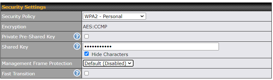
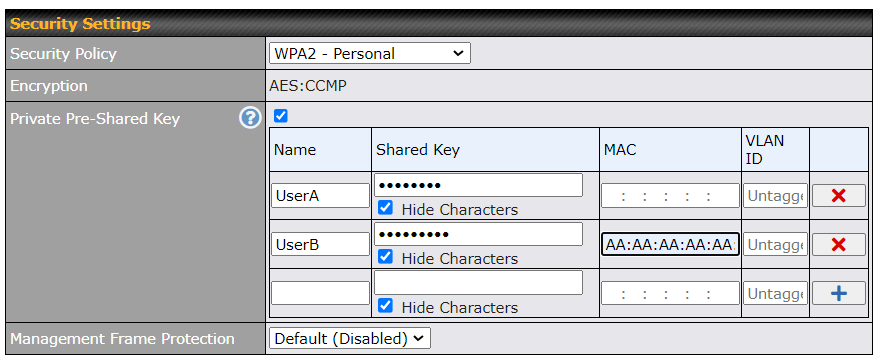
| WPA2 – Personal | |||||||||
| Private Shared Key | Enable the Private Pre-Shared Key (PPSK) option to set unique pre-shared keys for individual users or groups on the same SSID. Please provide the following information for each user or group:
*Each “Shared Key + MAC” combination must be unique in a different profile. |
||||||||
| Shared Key | Enter a passphrase of between 8 and 63 alphanumeric characters to create a passphrase used for data encryption and authentication. Click Hide / Show Characters to toggle visibility. | ||||||||
| Management Frame Protection | This feature protects stations against forged management frames spoofed from other devices. Frames that are protected include Disassociation, Deauthentication, and QoS Action. | ||||||||
| Fast Transition | Fast Transition
[802.11r] When this option is ticked, the transition process of a mobile client is improved as it moves between access points. |
||||||||

| WPA2 – Enterprise | |
| 802.1X Version | Choose v1 or v2 of the 802.1x EAPOL. When v1 is selected, both v1 and v2 clients can associate with the access point. When v2 is selected, only v2 clients can associate with the access point. Most modern wireless clients support v2. For stations that do not support v2, select v1. The default is v2. |
| Management Frame Protection | This feature protects stations against forged management frames spoofed from other devices. Frames that are protected include Disassociation, Deauthentication, and QoS Action. |
| Fast Transition | Fast Transition
[802.11r] When this option is ticked, the transition process of a mobile client is improved as it moves between access points. |

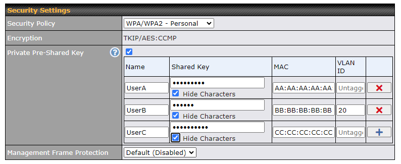
| WPA/WPA2 – Personal | |||||||||
| Private Shared Key | Enable the Private Pre-Shared Key (PPSK) option to set unique pre-shared keys for individual users or groups on the same SSID. Please provide the following information for each user or group:
*Each “Shared Key + MAC” combination must be unique in a different profile. |
||||||||
| Shared Key | Enter a passphrase of between 8 and 63 alphanumeric characters to create a passphrase used for data encryption and authentication. Click Hide / Show Characters to toggle visibility. | ||||||||
| Management Frame Protection | This feature protects stations against forged management frames spoofed from other devices. Frames that are protected include Disassociation, Deauthentication and QoS Action. | ||||||||

| WPA/WPA2 – Enterprise | |
| 802.1X Version | Choose v1 or v2 of the 802.1x EAPOL. When v1 is selected, both v1 and v2 clients can associate with the access point. When v2 is selected, only v2 clients can associate with the access point. Most modern wireless clients support v2. For stations that do not support v2, select v1. The default is v2. |
| Management Frame Protection | This feature protects stations against forged management frames spoofed from other devices. Frames that are protected include Disassociation, Deauthentication and QoS Action. |
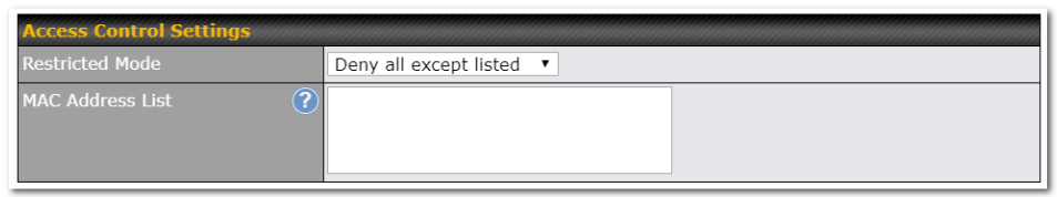
| Access Control Settings | |
| Restricted Mode | The settings allow the administrator to control access using MAC address filtering. Available options are None, Deny all except listed, Accept all except listed and Radius MAC Authentication. |
| MAC Address List | Connections coming from the MAC addresses in this list will be either denied or accepted based on the option selected in the previous field.
If more than one MAC address needs to be entered, you can use a carriage return to separate them. |
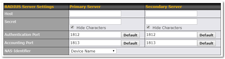
| RADIUS Server Settings | |
| Host | Enter the IP address of the primary RADIUS server and, if applicable, the secondary RADIUS server. |
| Secret | Enter the RADIUS shared secret for the primary server and, if applicable, the secondary RADIUS server. |
| Authentication Port | In the field, enter the UDP authentication port(s) used by your RADIUS server(s) or click the Default button to enter 1812. |
| Accounting Port | In the field, enter the UDP accounting port(s) used by your RADIUS server(s) or click the Default button to enter 1813. |
| NAS-Identifier | Choose between Device Name, LAN MAC address, Device Serial Number and Custom Value |
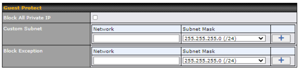
| Guest Protect | |
| Block All Private IP | Check this box to deny all connection attempts by private IP addresses. |
| Custom Subnet | To create a custom subnet for guest access, enter the IP address and choose a subnet mask from the drop-down menu. |
| Block Exception | To block access from a particular subnet, enter the IP address and choose a subnet mask from the drop-down menu. |
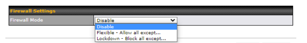
| Firewall Settings | |
| Firewall Mode | The settings allow administrators to control access to the SSID based on Firewall Rules.
Available options are Disable,Lockdown – Block all except… and Flexible -Allow all except… |
| Firewall Exceptions | Create Firewall Rules based on Port, IP Network, MAC address or Domain Name |
Wireless Mesh#
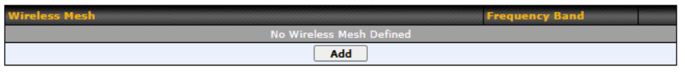
Wireless Mesh Support is available on devices running 802.11ac (Wi-Fi 5) and above. Along with the AP Controller, mesh network extensions can be established, which can expand network coverage. Note that the Wireless Mesh settings need to match the Mesh ID and Shared Key of the other devices on the same selected frequency band.
To create a new Wireless Mesh profile, go to AP > Wireless Mesh, and click Add.
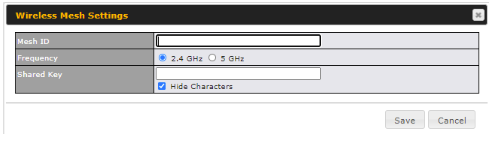
| Wireless Mesh Settings | |
| Mesh ID | Enter a name to represent the Mesh profile. |
| Frequency | Select the 2.4GHz or 5GHz frequency to be used. |
| Shared Key | Enter the shared key in the text field. Please note that it needs to match the shared keys of the other APs in the Wireless Mesh settings.
Click Hide / Show Characters to toggle visibility. |
AP > Profiles#
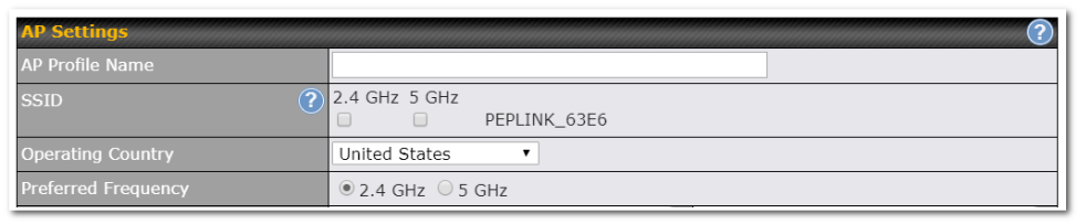
| AP Settings | |
| AP Profile Name | Ap Profile name |
| SSID | You can select the wireless networks for 2.4 GHz or 5 GHz separately for each SSID. |
| Operating Country | This drop-down menu specifies the national/regional regulations which the Wi-Fi radio should follow.
NOTE: Users are required to choose an option suitable to local laws and regulations. |
| Preferred Frequency | Indicate the preferred frequency to use for clients to connect. |
| Important Note |
| Per FCC regulation, the country selection is not available on all models marketed in the US. All US models are fixed to US channels only. |
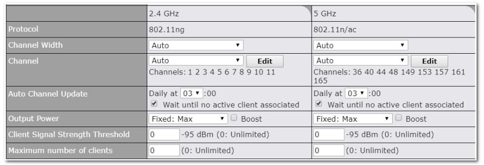
| AP Settings (part 2) | |
| Protocol | This option allows you to specify whether 802.11b and/or 802.11g client association requests will be accepted. Available options are 802.11ng and 802.11na. By default, 802.11ng is selected. |
| Channel Width | Available options are 20 MHz, 40 MHz, and Auto (20/40 MHz) . Default is Auto (20/40 MHz), which allows both widths to be used simultaneously. |
| Channel | This option allows you to select which 802.11 RF channel will be utilized. Channel 1 (2.412 GHz) is selected by default. |
| Auto Channel Update | Indicate the time of day at which update automatic channel selection. |
| Output Power | This option is for specifying the transmission output power for the Wi-Fi AP. There are 4 relative power levels available – Max, High, Mid, and Low. The actual output power will be bound by the regulatory limits of the selected country. |
| Client Signal Strength Threshold | Clients with signal strength lower than this value will not be allowed to connect. |
| Maximum number of clients | This setting determines the maximum number of clients that can connect to this Wi-Fi frequency. |
Advanced Wi-Fi AP settings can be displayed by clicking the ![]() on the top right-hand corner of the Wi-Fi AP Settings section, which can be found at AP>Settings. Other models will display a separate section called Wi-Fi AP Advanced Settings, which can be found at Advanced>Wi-Fi Settings.
on the top right-hand corner of the Wi-Fi AP Settings section, which can be found at AP>Settings. Other models will display a separate section called Wi-Fi AP Advanced Settings, which can be found at Advanced>Wi-Fi Settings.
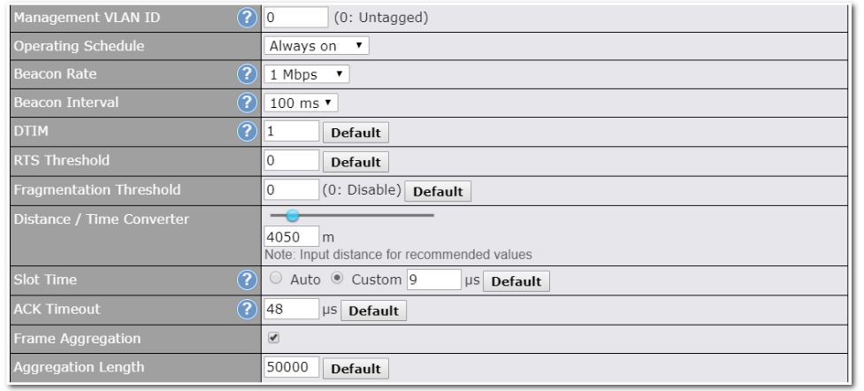
| Advanced AP Settings | |
| Management VLAN ID | This field specifies the VLAN ID to tag to management traffic, such as communication traffic between the AP and the AP Controller. The value is zero by default, which means that no VLAN tagging will be applied.
NOTE: Change this value with caution as alterations may result in loss of connection to the AP Controller. |
| Operating Schedule | Choose from the schedules that you have defined in System>Schedule. Select the schedule for the integrated AP to follow from the drop-down menu. |
| Beacon Rate A | This option is for setting the transmit bit rate for sending a beacon. By default, 1Mbps is selected. |
| Beacon Interval A | This option is for setting the time interval between each beacon. By default, 100ms is selected. |
| DTIM A | This field allows you to set the frequency for the beacon to include delivery traffic indication messages. The interval is measured in milliseconds. The default value is set to 1 ms. |
| RTS Threshold A | The RTS (Request to Clear) threshold determines the level of connection required before the AP starts sending data. The recommended standard of the RTS threshold is around 500. |
| Fragmentation Threshold A | This setting determines the maximum size of a packet before it gets fragmented into multiple pieces. |
| Distance / Time Convertor | Select the range you wish to cover with your Wi-Fi, and the router will make recommendations for the Slot Time and ACK Timeout. |
| Slot Time A | This field is for specifying the unit wait time before transmitting a packet. By default, this field is set to 9 µs. |
| ACK Timeout A | This field is for setting the wait time to receive an acknowledgement packet before performing a retransmission. By default, this field is set to 48 µs. |
| Frame Aggregation A | This option allows you to enable frame aggregation to increase transmission throughput. |
A – Advanced feature, please click the ![]() button on the top right-hand corner to activate.
button on the top right-hand corner to activate.
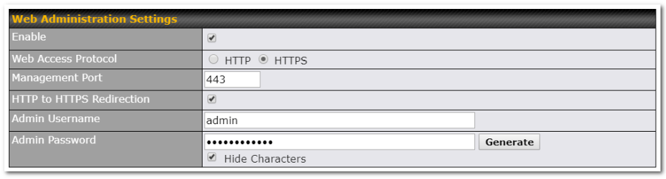
| Web Administration Settings | |
| Enable | Ticking this box enables web admin access for APs located on the WAN. |
| Web Access Protocol | Determines whether the web admin portal can be accessed through HTTP or HTTPS |
| Management Port | Determines the port at which the management UI can be accessed. |
| HTTP to HTTPS redirection | Redirects HTTP request to HTTPS |
| Admin Username | Determines the username to be used for logging into the web admin portal |
| Admin Password | Determines the password for the web admin portal on external AP. |
AP Controller Status#
Info#
A comprehensive overview of your AP can be accessed by navigating to AP > Info.
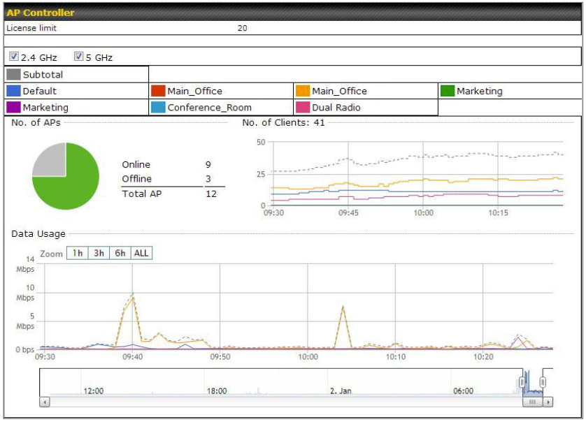
| AP Controller | |
| License Limit | This field displays the maximum number of AP your Balance router can control. You can purchase licenses to increase the number of AP you can manage. |
| Frequency | Underneath, there are two check boxes labeled 2.4 Ghz and 5 Ghz. Clicking either box will toggle the display of information for that frequency. By default, the graphs display the number of clients and data usage for both 2.4GHz and 5 GHz frequencies. |
| SSID | The colored boxes indicate the SSID to display information for. Clicking any colored box will toggle the display of information for that SSID. By default, all the graphs show information for all SSIDs. |
| No. of APs | This pie chart and table indicates how many APs are online and how many are offline. |
| No.of Clients | This graph displays the number of clients connected to each network at any given time. Mouse over any line on the graph to see how many clients connected to a specific SSID for that point in time. |
| Data Usage | This graph enables you to see the data usage of any SSID for any given time period. Mouse over any line on the graph to see the data usage by each SSID for that point in time. Use the buttons next to Zoom to select the time scale you wish to view. In addition, you could use the sliders at the bottom to further refine your timescale. |
Access Points (Usage)#
A detailed breakdown of data usage for each AP is available at AP> Access Point.
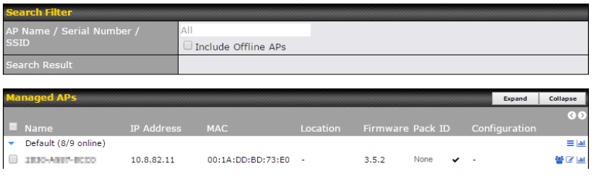
|
Usage |
|
| AP Name/Serial Number | This field enables you to quickly find your device if you know its name or serial number. Fill in the field to begin searching. Partial names and serial numbers are supported. |
| Online Status | This button toggles whether your search will include offline devices. |
| Managed Wireless Devices | This table shows the detailed information on each AP, including channel, number of clients, upload traffic, and download traffic. Click the blue arrows at the left of the table to expand and collapse information on each device group. You could also expand and collapse all groups by using the On the right of the table, you will see the following icons: Click the
For easier network management, you can give each client a name and designate its location. You can also designate which firmware pack (if any) this client will follow, as well as the channels on which the client will broadcast. Click the
Click any point in the graphs to display detailed usage and client information for that device, using that SSID, at that point in time. On the Data Usage by menu, you can display the information by SSID or by AP send/receive rate. Click the Event tab next to Wireless Usage to view a detailed event log for that particular device:
|
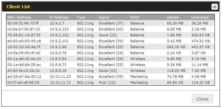
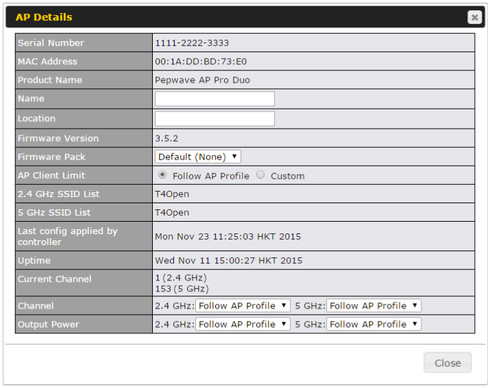
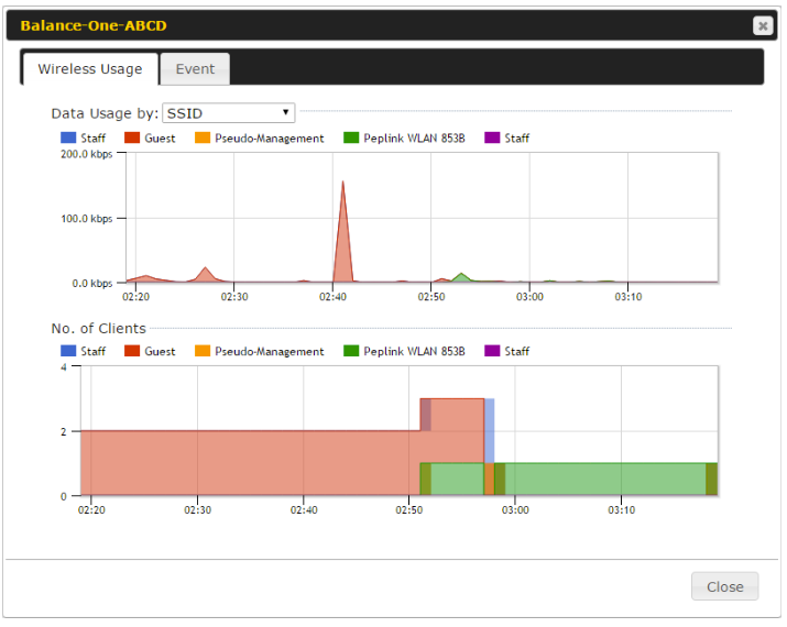
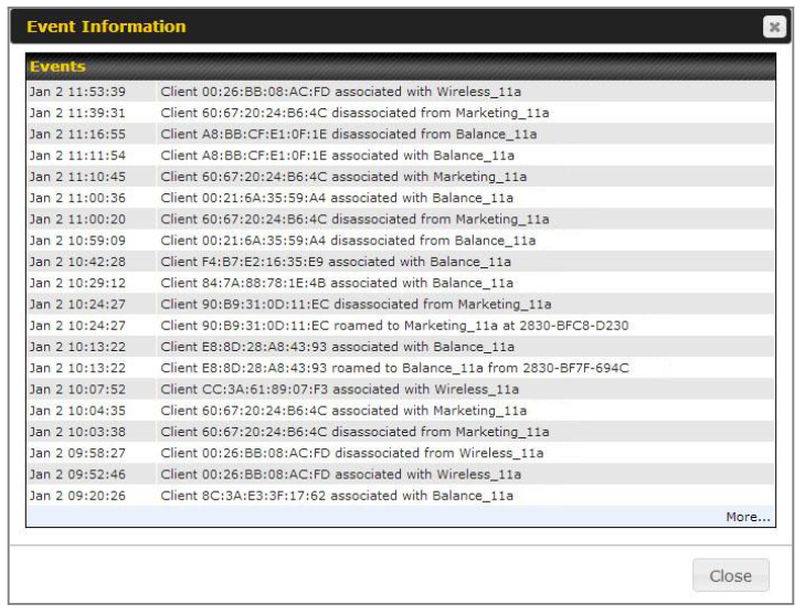
Wireless SSID#
In-depth wireless SSID reports are available under AP > Wireless SSID.
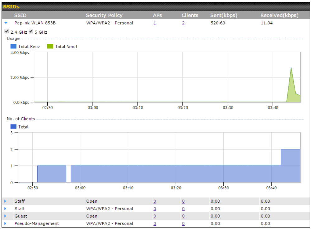
Click the blue arrow on any SSID to obtain more detailed usage information on each SSID.
Wireless Client#
You can search for specific Wi-Fi users by navigating to AP > Wireless Client.
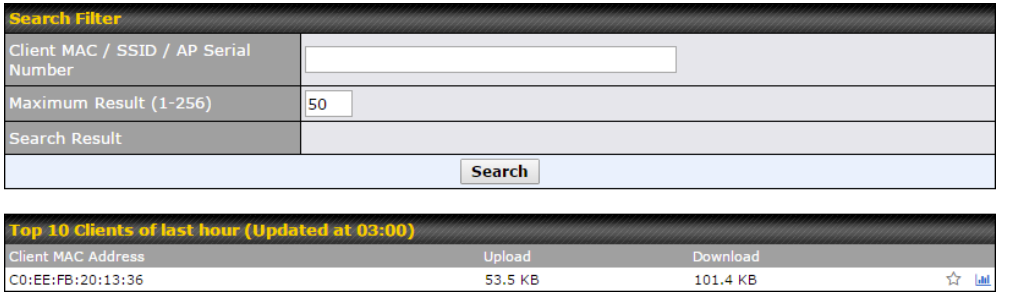
Here, you will be able to see your network’s heaviest users as well as search for specific users. Click the ![]() icon to bookmark specific users, and click the
icon to bookmark specific users, and click the ![]() icon for additional details about each user:
icon for additional details about each user:
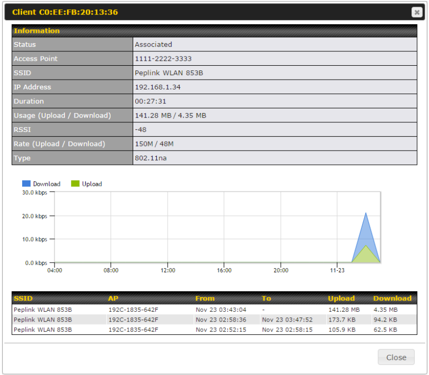
Mesh / WDS#
Mesh / WDS allows you to monitor the status of your wireless distribution system (WDS) or Mesh, and track activity by MAC address by navigating to AP > Controller Status > Mesh / WDS. This table shows the detailed information of each AP, including protocol, transmit rate (sent / received), signal strength, and duration.
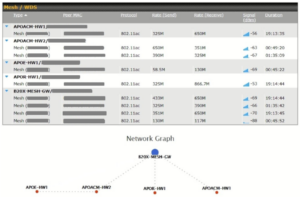
Nearby Device#
A listing of near devices can be accessed by navigating to AP > Controller Status > Nearby Device.
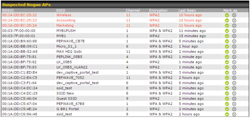
| Nearby Devices |
| Hovering over the device MAC address will result in a popup with information on how this device was detected. Click the |
Event Log#
You can access the AP Controller Event log by navigating to AP > Controller Status > Event Log.
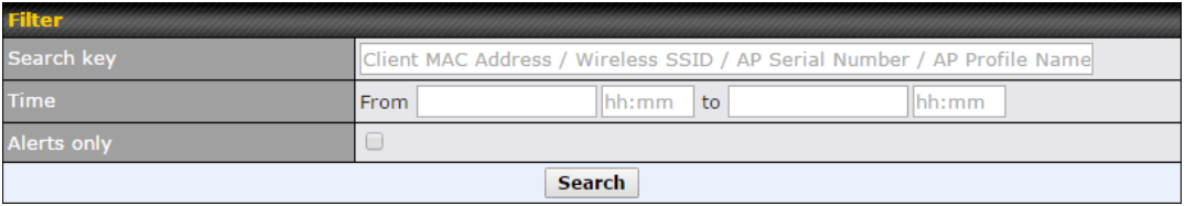
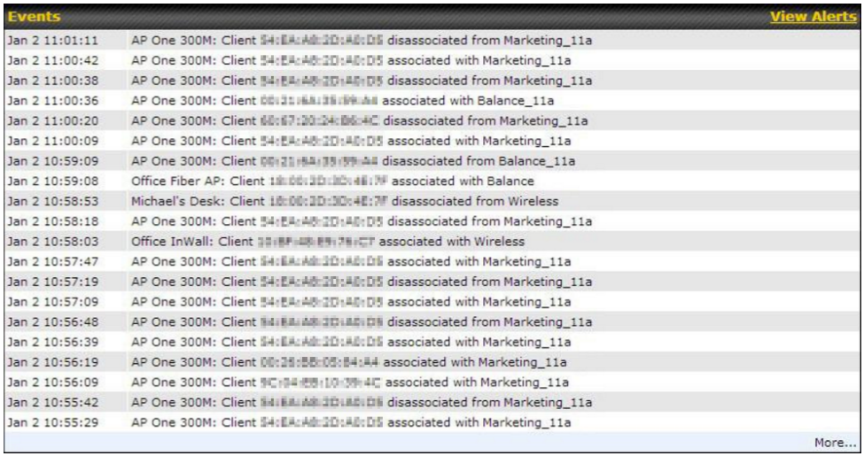
| Events |
| This event log displays all activity on your AP network, down to the client level. Use to filter box to search by MAC address, SSID, AP Serial Number, or AP Profile name. Click View Alerts to see only alerts, and click the More… link for additional records. |
Toolbox#
Additional tools for managing firmware packs, power adjustment, and channel assignment can be found at AP>Toolbox.
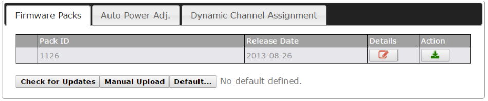
| Firmware Packs |
| This is the first menu that will appear. Here, you can manage the firmware of your AP. Clicking on |
Ch14. Switch#
Switch Controller
Navigate to Switch Tab > Switch Controller > Controller.
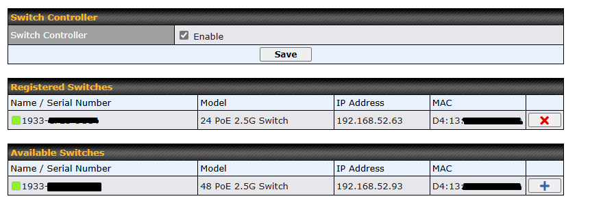
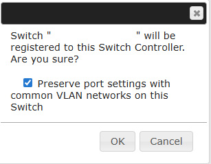
| Switch Controller | |
| Registered Switches | List of registered switches. Press “X” to remove the selected switch from the list. |
| Available Switches | List of available switches connected to the device. Press “+” to register the selected switch to the Registered Switches list.
Note: When option “Preserve port settings with common VLAN networks on this Switch” is tick when register selected switch, the port settings which VLANs are defined in Switch Controller will be preserved. Else, will be replaced by VLAN 1. |
NOTE: PoE 2.5G Switch will only be managed by either InControl or Device switch controller. Do not enable the Switch Controller if the switch needs to be managed by InControl.
Admin Security
Navigate to Switch Tab > Switch Controller > Admin Security.
There are two types of user accounts available for accessing the Web Admin: admin and user. The admin login has full administrative access, while the user login is read-only. The user level can access only the device’s status information; users cannot make any changes on the device.
A web login session will be logged out automatically when it has been idle longer than the Web Session Timeout. Before the session expires, you may click the Logout button in the web admin to exit the session.
0 hours 0 minutes signifies an unlimited session time. This setting should be used only in special situations, as it will lower the system security level if users do not log out before closing the browser. The default is 4 hours, 0 minutes.
For security reasons, after logging in to the web admin Interface for the first time, it is recommended to change the administrator password. Configuring the administration interface to be accessible only from the LAN can further improve system security. Administrative settings configuration is located at System>Admin Security.
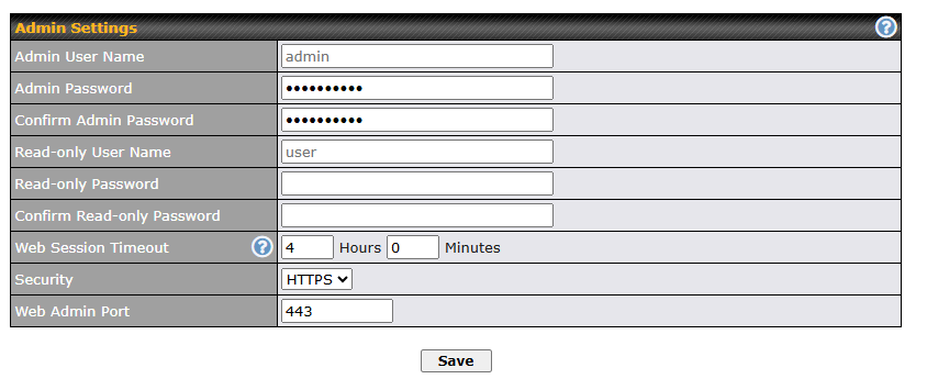
| Admin Settings | |
| Admin User Name | Admin User Name is set as admin by default, but can be changed, if desired. |
| Admin Password | This field allows you to specify a new administrator password. |
| Confirm Admin Password | This field allows you to verify and confirm the new administrator password. |
| Read-only User Name | Read-only User Name is set as user by default, but can be changed, if desired. |
| Read-only Password | This field allows you to specify a new user password. Once the user password is set, the read-only user feature will be enabled. |
| Confirm Read-only Password | This field allows you to verify and confirm the new user password. |
| Web Session Timeout | This field specifies the number of hours and minutes that a web session can remain idle before the Pepwave router terminates its access to the web admin interface. By default, it is set to 4 hours. |
| Security | This option is for specifying the protocol(s) through which the web admin interface can be accessed:
Default will be HTTPS. |
| Web Admin Port | This field is for specifying the port number on which the web admin interface can be accessed. |
Switch Information
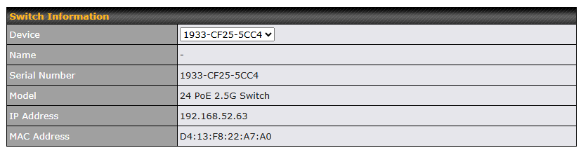
| Switch Information | |
| Device | Drop down list to select Switch to be configured. |
| Name | Name of the switch.(not sure where to define) |
| Serial Number | Selected switch serial number. |
| Model | Selected switch model. |
| IP Address | Uplink IP address of the selected switch. |
| MAC Address | Selected switch MAC address. |
STP
Navigate to Switch Tab > STP.
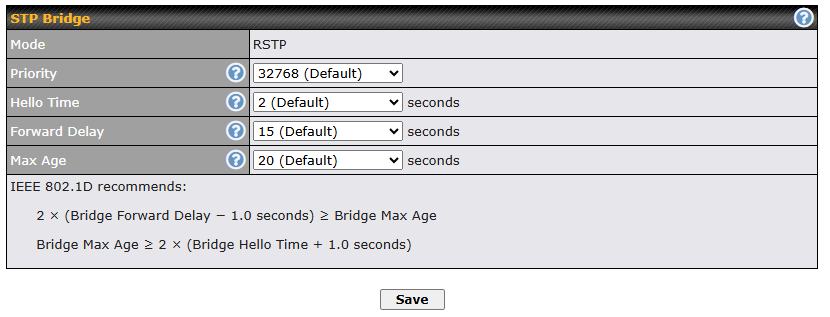
(A) – Advanced feature. Click the |
|||||||||||||
Switch Ports
Navigate to Switch Tab > Interfaces > Switch Ports.
For each port, you can set PoE scheduling, port type (Trunk and Access), as well as the VLAN which they belong to.

To configure port, you may click on the port icon or the pen icon from the Port Settings table to show the Port parameters.

| Port Settings | |
| Name | Set a name for the port |
| Enable checkbox | Enables / Disables the Port |
| PoE Enable checkbox | Enables / Disables PoE on the Port |
| Speed^ | Set the port speed to Auto, 10 Mbps half/full duplex or 100 Mbps half/full duplex, or 1GB full duplex. |
| Port Type | Set as Trunk or Access |
| VLAN Networks | Designate one or more VLANs to be used on this port. |
| PVID** | Untagged frames received by the port are classified to a VLAN indicated by Port VLAN Identifier (PVID). All frames from the VLAN are untagged on egress.** |
| RSTP checkbox | Enables or Disables Rapid Spanning Tree Protocol |
** PVID option is only configurable when Port Type is set to “Trunk”.
^ Configuration options on certain ports are configurable port speeds to 2.5 Gbps. May refer to the datasheet or label below switch ports.
^ Configurable options on SFP+ ports are similar as above, but configurable port speeds are between 100 Mbps Full Duplex up to 10 Gbps Full Duplex.
LACP (802.3ad) Configuration
LACP is part of the IEEE specification 802.3ad and allows you to bundle several physical ports to form a single logical channel.
Bundling multiple physical ports into a single logical link allows you to increase throughput beyond the limitations of a single connection and provides redundancy in case one link goes down.
Select multiple ports by clicking on them and selecting the Link Aggregation checkbox to enable link aggregation for the selected ports.
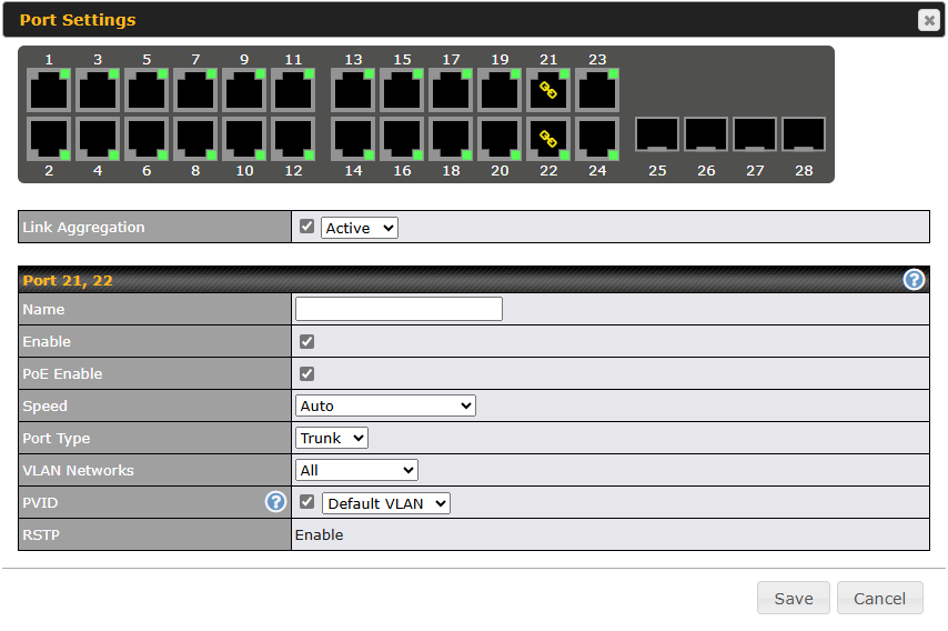
Ch15. System Tab#
System#
Admin Security#
There are two types of user accounts available for accessing the web admin: admin and user. They represent two user levels: the admin level has full administrative access, while the user level is read-only. The user level can access only the device’s status information; users cannot make any changes on the device.
A web login session will be logged out automatically when it has been idle longer than the Web Session Timeout. Before the session expires, you may click the Logout button in the web admin to exit the session.
0 hours 0 minutes signifies an unlimited session time. This setting should be used only in special situations, as it will lower the system security level if users do not log out before closing the browser. The default is 4 hours, 0 minutes.
For security reasons, after logging in to the web admin Interface for the first time, it is recommended to change the administrator password. Configuring the administration interface to be accessible only from the LAN can further improve system security. Administrative settings configuration is located at System>Admin Security.
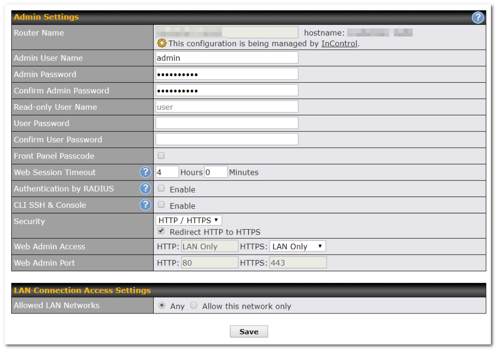
| Admin Settings | |||||||||||||||||||||||||
| Router Name | This field allows you to define a name for this Pepwave router. By default, Router Name is set as MAX_XXXX, where XXXX refers to the last 4 digits of the unit’s serial number. | ||||||||||||||||||||||||
| Admin User Name | Admin User Name is set as admin by default, but can be changed, if desired. | ||||||||||||||||||||||||
| Admin Password | This field allows you to specify a new administrator password. | ||||||||||||||||||||||||
| Confirm Admin Password | This field allows you to verify and confirm the new administrator password. | ||||||||||||||||||||||||
| Read-only User Name | Read-only User Name is set as user by default, but can be changed, if desired. | ||||||||||||||||||||||||
| User Password | This field allows you to specify a new user password. Once the user password is set, the read-only user feature will be enabled. | ||||||||||||||||||||||||
| Confirm User Password | This field allows you to verify and confirm the new user password. | ||||||||||||||||||||||||
| Web Session Timeout | This field specifies the number of hours and minutes that a web session can remain idle before the Pepwave router terminates its access to the web admin interface. By default, it is set to 4 hours. | ||||||||||||||||||||||||
| Authentication Method | With this box is checked, the web admin will authenticate using an external RADIUS server. Authenticated users are treated as either “admin” with full read-write permission or “user” with read-only access. Local admin and user accounts will be disabled. When the device is not able to communicate with the external RADIUS server, local accounts will be enabled again for emergency access. Additional authentication options will be available once this box is checked.
Available options:
|
||||||||||||||||||||||||
| Network Connection | This option is for specifying the network connection to be used for authentication. Users can choose from LAN, WAN, and VPN connections. | ||||||||||||||||||||||||
| Restricted Admin Access | When the “by Management Port Only” is enabled, this option allows you to access the device WebAdmin/SSH by physical connect to the MGMT port. | ||||||||||||||||||||||||
| CLI SSH | The CLI (command line interface) can be accessed via SSH. This field enables CLI support. For additional information regarding CLI, please refer to Section 15.3. | ||||||||||||||||||||||||
| CLI SSH Access | This menu allows you to choose between granting access to LAN and WAN clients, or to LAN clients only. | ||||||||||||||||||||||||
| CLI SSH Port | This field determines the port on which clients can access CLI SSH. | ||||||||||||||||||||||||
| CLI SSH Login Grace Time | This option specifies the time for CLI SSH login. The default value is 120. | ||||||||||||||||||||||||
| CLI SSH Access Public Key | This field is for entering the Public Key for Admin Users and Read-only Users to access CLI SSH. | ||||||||||||||||||||||||
| Security | This option is for specifying the protocol(s) through which the web admin interface can be accessed:
HTTP to HTTPS redirection is enabled by default to force HTTPS access to the web admin interface. |
||||||||||||||||||||||||
| Web Admin Port | This field is for specifying the port number on which the web admin interface can be accessed. | ||||||||||||||||||||||||
| Web Admin Access | This option is for specifying the network interfaces through which the web admin interface can be accessed:
If LAN/WAN is chosen, the WAN Connection Access Settings form will be displayed. |
||||||||||||||||||||||||

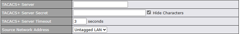

| LAN Connection Access Settings | |
| Allowed LAN Networks | This field allows you to permit only specific networks or VLANs to access the Web UI. |
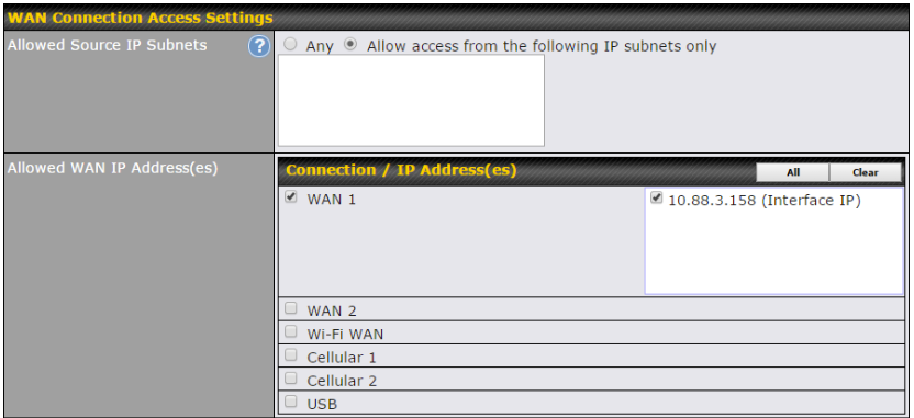
| WAN Connection Access Settings | |
| Allowed Source IP Subnets | This field allows you to restrict web admin access only from defined IP subnets.
The allowed IP subnet addresses should be entered into this text area. Each IP subnet must be in form of w.x.y.z/m, where w.x.y.z is an IP address (e.g., 192.168.0.0), and m is the subnet mask in CIDR format, which is between 0 and 32 inclusively (For example, 192.168.0.0/24). To define multiple subnets, separate each IP subnet one in a line. For example:
|
| Allowed WAN IP Address(es) | This is to choose which WAN IP address(es) the web server should listen on. |
Firmware#
Upgrading firmware can be done in one of three ways.
Using the router’s interface to automatically check for an update, using the router’s interface to manually upgrade the firmware, or using InControl2 to push an upgrade to a router.
The automatic upgrade can be done from System > Firmware.
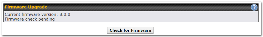
If an update is found the buttons will change to allow you to Download and Update the firmware.
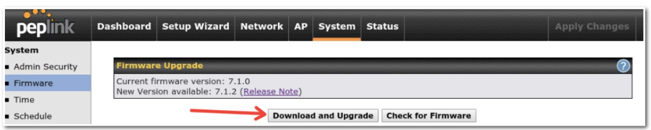
Click on the Download and Upgrade button. A prompt will be displayed advising to download the Current Active Configuration. Please click on the underlined download text. After downloading the current config click the Ok button to start the upgrade process.
The router will download and then apply the firmware. The time that this process takes will depend on your internet connection’s speed.
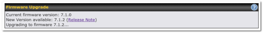
The firmware will now be applied to the router*. The amount of time it takes for the firmware to upgrade will also depend on the router that’s being upgraded.
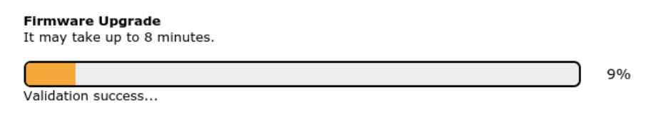
*Upgrading the firmware will cause the router to reboot.
Web admin interface: install updates manually
In some cases, a special build may be provided via a ticket or it may be found in the forum. Upgrading to the special build can be done using this method, or using IC2 if you are using that to manage your firmware upgrades. A manual upgrade using the GA firmware posted on the site may also be recommended or required for a couple of reasons.
All of the Peplink/Pepwave GA firmware can be found here Navigate to the relevant product line (ie. Balance, Max, FusionHub, etc). Some product lines may have a dropdown that lists all of the products in that product line. Here is a screenshot from the Balance line.
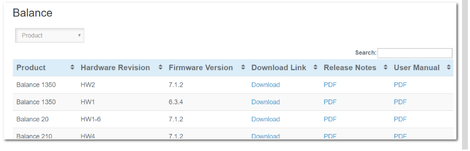
If the device has more than one firmware version the current hardware revision will be required to know what firmware to download.
Navigate to System > Firmware and click the Choose File button under the Manual Firmware Upgrade section. Navigate to the location that the firmware was downloaded to select the “.img” file and click the Open button.
Click on the Manual Upgrade button to start the upgrade process.
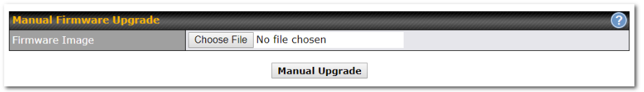
A prompt will be displayed advising to download the Current Active Configuration. Please click on the underlined download text. After downloading the current config click the Ok button to start the upgrade process. The firmware will now be applied to the router*. The amount of time it takes for the firmware to upgrade will depend on the router that’s being upgraded.
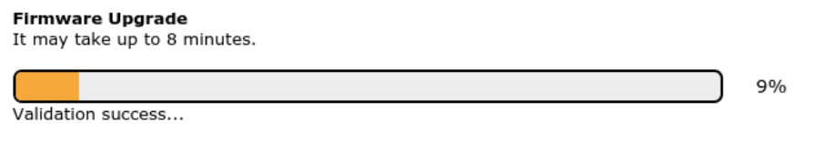
*Upgrading the firmware will cause the router to reboot.
The InControl method
Described in this knowledgebase article on our forum.
Time#
Time Settings enables the system clock of the Peplink router to be synchronized with a specified time server. Time settings are located at System>Time.

| Time Settings | |
| Time Zone | This specifies the time zone (along with the corresponding Daylight Savings Time scheme). The Time Zone value affects the time stamps in the Peplink router’s event log and e-mail notifications. Check Show all to show all time zone options. |
| Time Sync | This field allows to select your time sync mode, the available options are:
|
| Time Server | This setting specifies the NTP network time server to be utilized by the router.
NOTE: Multiple NTP servers can be added starting from firmware version 8.5.3. |
| Time Server Source Network Address | This setting is to specific which VLAN network will be used for NTP traffic. |
Schedule#
Enable and disable different functions (such as WAN connections, outbound policy, and firewalls at different times, based on a user-scheduled configuration profile. The settings for this are located at System > Schedule.
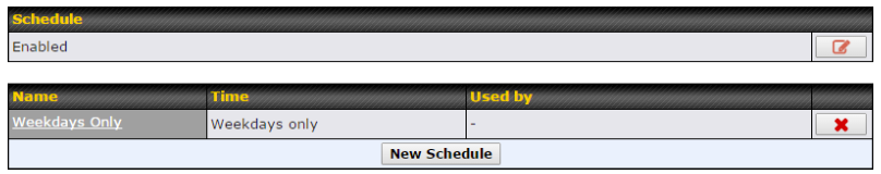
Enable scheduling, and then click on your schedule name or on the New Schedule button to begin.

| Edit Schedule Profile | |
| Enabling | Click this checkbox to enable this schedule profile. Note that if this is disabled, then any associated features will also have their scheduling disabled. |
| Name | Enter your desired name for this particular schedule profile. |
| Schedule | Click the drop-down menu to choose pre-defined schedules as your starting point. Please note that upon selection, previous changes on the schedule map will be deleted. |
| Schedule Map | Click on the desired times to enable features at that time period. You can hold your mouse for faster entry. |
Email Notification#
The email notification functionality of the Peplink Balance provides a system administrator with up-to-date information on network status. The settings for configuring email notification are found at System>Email Notification.
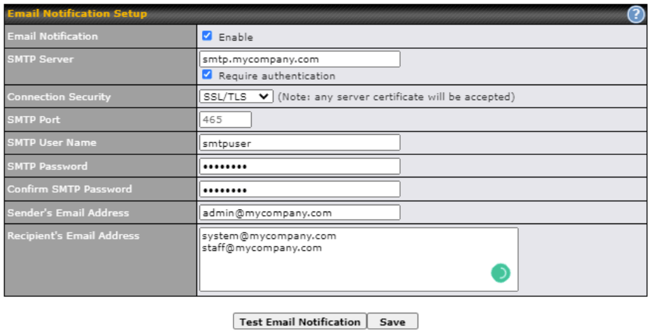
| Email Notification Settings | |
| Email Notification | This setting specifies whether or not to enable email notification. If Enable is checked, the Peplink Balance will send email messages to system administrators when the WAN status changes or when new firmware is available. If Enable is not checked, email notification is disabled and the Peplink Balance will not send email messages. |
| SMTP Server | This setting specifies the SMTP server to be used for sending email. If the server requires authentication, check Require authentication. |
| Connection Security | This setting specifies via a drop-down menu one of the following valid Connection Security:
|
| SMTP Port | This field is for specifying the SMTP port number. By default, this is set to 25. If Connection Security is selected “STARTTLS”, the default port number will be set to 587. If Connection Security is selected “SSL/TLS”, the default port number will be set to 465.
You may customize the port number by editing this field. |
| SMTP User Name / Password | This setting specifies the SMTP username and password while sending email. These options are shown only if Require authentication is checked in the SMTP Server setting. |
| Confirm SMTP Password | This field allows you to verify and confirm the new administrator password. |
| Sender’s Email Address | This setting specifies the email address which the Peplink Balance will use to send its reports. |
| Recipient’s Email Address | This setting specifies the email address(es) to which the Peplink Balance will send email notifications. For multiple recipients, separate each email using the enter key. |
After you have finished setting up email notifications, you can click the Test Email Notification button to test the settings before saving. After Test Email Notification is clicked, you will see this screen to confirm the settings:
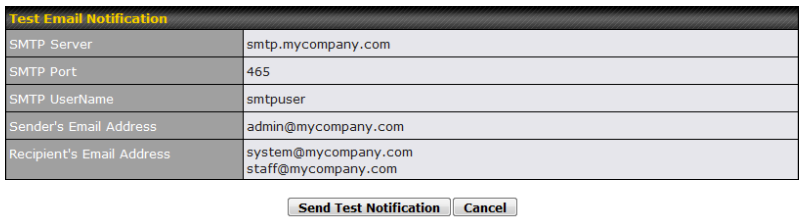
Click Send Test Notification to confirm. In a few seconds, you will see a message with detailed test results.
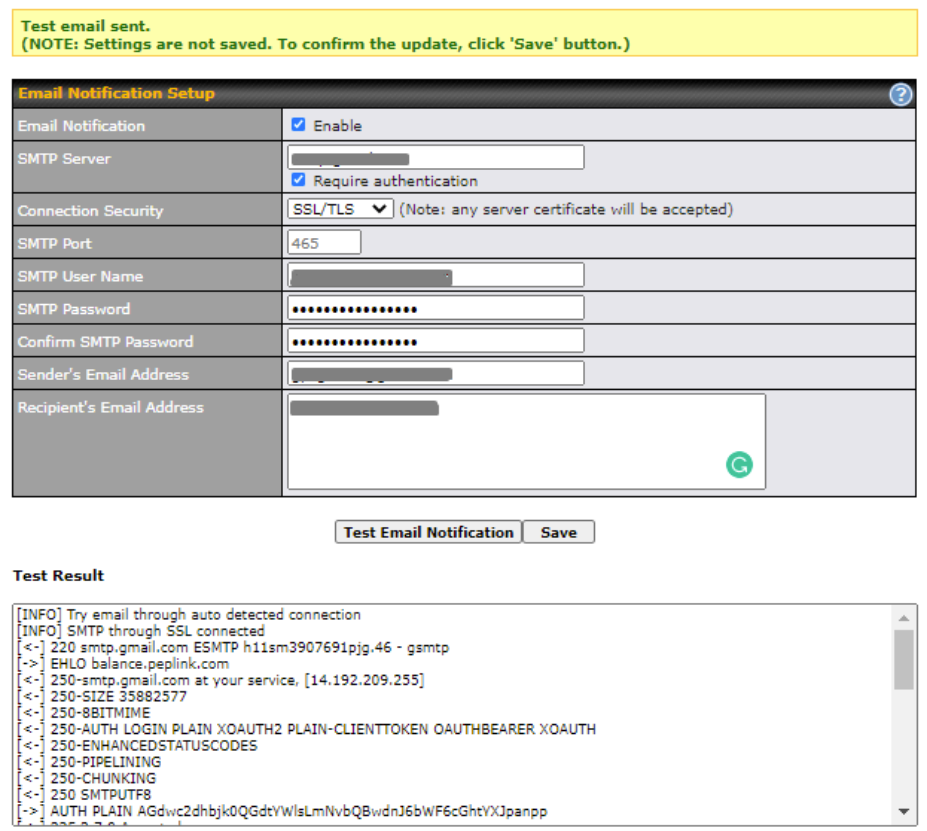
Event Log#
Event log functionality enables event logging at a specified remote syslog server. The settings for configuring the remote system log can be found at System>Event Log.
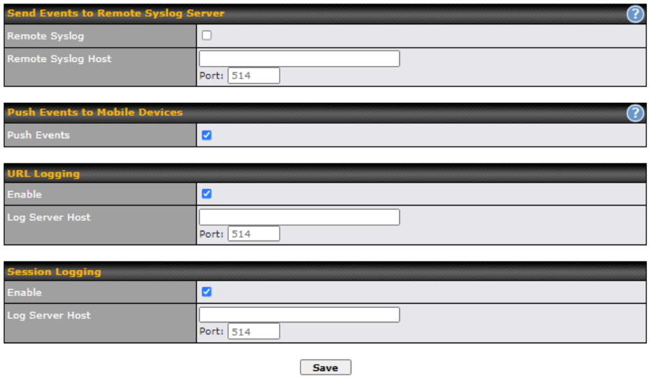
| Remote Syslog Settings | |
| Remote Syslog | This setting specifies whether or not to log events at the specified remote syslog server. |
| Remote Syslog Host | This setting specifies the IP address or hostname of the remote syslog server. |
| Push Events | The Peplink Balance can also send push notifications to mobile devices that have our Mobile Router Utility installed. Check the box to activate this feature. |
| URL Logging | This setting is to enable event logging at the specified log server. |
| URL Logging Host | This setting specifies the IP address or hostname of the URL log server. |
| Session Logging | This setting is to enable event logging at the specified log server. |
| Session Logging Host | This setting specifies the IP address or hostname of the Session log server. |
 |
For more information on the Router Utility, go to: www.peplink.com/products/router-utility |
SNMP#
SNMP or simple network management protocol is an open standard that can be used to collect information about the Peplink Balance unit. SNMP configuration is located at System>SNMP.
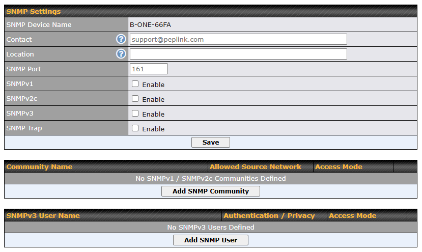
| SNMP Settings | |
| SNMP Device Name | This field shows the router name defined at System>Admin Security. |
| Contact | This field to input sysContact. The default contact is [email protected] |
| Location | This field to input sysLocation. |
| SNMP Port | This option specifies the port which SNMP will use. The default port is 161. |
| SNMPv1 | This option allows you to enable SNMP version 1. |
| SNMPv2 | This option allows you to enable SNMP version 2. |
| SNMPv3 | This option allows you to enable SNMP version 3. |
| SNMP Trap | This option allows you to enable SNMP Trap. If enabled, the following entry fields will appear. |
| SNMP Trap Community | This setting specifies the SNMP Trap community name. |
| SNMP Trap Server | Enter the IP address of the SNMP Trap server |
| SNMP Trap Port | This option specifies the port which the SNMP Trap server will use. The default port is 162. |
| SNMP Trap Server Heartbeat | This option allows you to enable and configure the heartbeat interval for the SNMP Trap server. |
To add a community for either SNMPv1 or SNMPv2, click the Add SNMP Community button in the Community Name table, upon which the following screen is displayed:
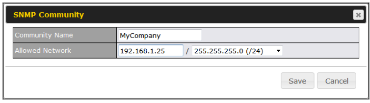
| SNMP Community Settings | |
| Community Name | This setting specifies the SNMP community name. |
| Allowed Source Subnet Address | This setting specifies a subnet from which access to the SNMP server is allowed. Enter subnet address here (e.g., 192.168.1.0) and select the appropriate subnet mask. |
To define a user name for SNMPv3, click Add SNMP User in the SNMPv3 User Name table, upon which the following screen is displayed:
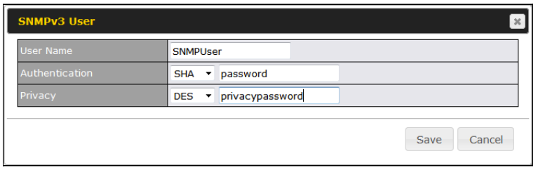
| SNMPv3 User Settings | |
| User Name | This setting specifies a user name to be used in SNMPv3. |
| Authentication Protocol | This setting specifies via a drop-down menu one of the following valid authentication protocols:
When MD5 or SHA is selected, an entry field will appear for the password. |
| Privacy Protocol | This setting specifies via a drop-down menu one of the following valid privacy protocols:
When DES is selected, an entry field will appear for the password. |
SMS Control#
SMS Control allows the user to control the device using SMS even if the modem does not have a data connection. The settings for configuring the SMS Control can be found at System>SMS Control.
Note: Supported Models
- Balance/MAX: *-LTE-E, *-LTEA-W, *-LTEA-P, *-LTE-MX
- EPX: *-LW*, *-LP*

When this box is checked, the device will be allowed to take actions according to received commands via SMS.
Make sure your mobile plan supports SMS, and note that some plans may incur additional charges for this.
SMS Control can reboot devices and configure cellular settings over signalling channels, even if the modem does not have an active data connection.
For details of supported SMS command sets, please refer to our knowledge base.
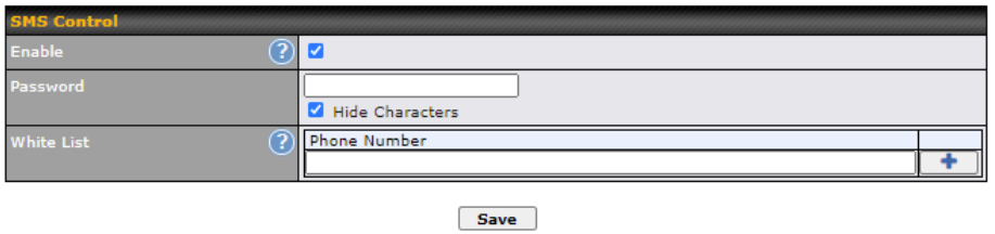
| SMS Control Settings | |
| Enable | Click the checkbox to enable the SMS Control. |
| Password | This setting sets the password for authentication – maximum of 32 characters, which cannot include semicolon (;). |
| White List | Optionally, you can add phone number(s) to the whitelist. Only matching phone numbers are allowed to issue SMS commands. Phone numbers must be in the E.164 International Phone Numbers format. |
InControl#
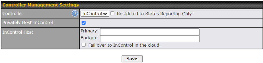
InControl is a cloud-based service which allows you to manage all of your Peplink and Pepwave devices with one unified system. With it, you can generate reports, gather statistics, and configure your devices automatically. All of this is now possible with InControl.
When this checkbox is checked, the device’s status information will be sent to the Peplink InControl system. This device’s usage data and configuration will be sent to the system if you enable the features in the system.
When the box Restricted to Status Reporting Only is ticked, the router will only report its status, but can’t be managed or configured by InControl.
Alternatively, you can also privately host InControl. Simply check the “Privately Host InControl” box and enter the IP Address of your InControl Host. If you have multiple hosts, you may enter the primary and backup IP addresses for the InControl Host and tick the “Fail over to InControl in the cloud” box. The device will connect to either the primary InControl Host or the secondary/backup ICA/IC2.
You can sign up for an InControl account at https://incontrol2.peplink.com/. You can register your devices under the account, monitor their status, see their usage reports, and receive offline notifications.
Configuration#
Backing up Peplink Balance settings immediately after successful completion of initial setup is strongly recommended. The functionality to download and upload Peplink Balance settings is found at System>Configuration.
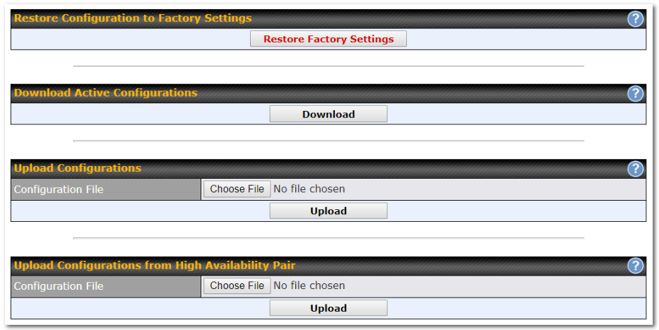
| Configuration | |
| Restore Configuration to Factory Settings | The Restore Factory Settings button is to reset the configuration to factory default settings. After clicking the button, you will need to click the Apply Changes button on the top right corner to make the settings effective. |
| Download Active Configurations | Click Download to backup the current active settings. |
| Upload Configurations | To restore or change settings based on a configuration file, click Choose File to locate the configuration file on the local computer, and then click Upload. The new settings can then be applied by clicking the Apply Changes button on the page header, or you can cancel the procedure by pressing discard on the main page of the web admin interface. |
| Upload Configurations from High Availability Pair | In a high availability (HA) configuration, the Balance unit can quickly load the configuration of its HA counterpart. To do so, click the Upload button. After loading the settings, configure the LAN IP address of the Peplink Balance unit so that it is different from the HA counterpart. |
Feature Add-ons#
Some balance models have features that can be activated upon purchase. Once the purchase is complete, you will receive an activation key. Enter the key in the Activation Key field, click Activate, and then click Apply Changes.
Reboot#
This page provides a reboot button for restarting the system. For maximum reliability, the Peplink Balance Series can be equipped with two copies of firmware, and each copy can be a different version. You can select the firmware version you would like to reboot the device with. The firmware marked with (Running) is the current system boot up firmware.
Please note that a firmware upgrade will always replace the inactive firmware partition.
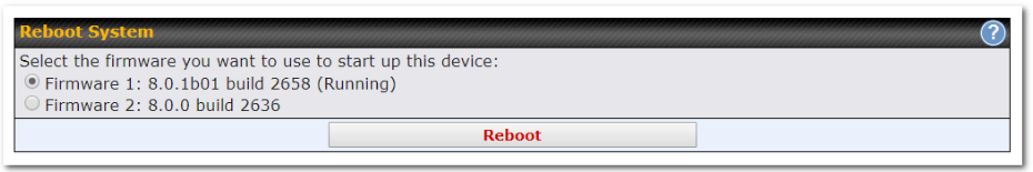
Tools#
Ping#
The ping test tool sends pings through a specific Ethernet interface or a SpeedFusionTM VPN connection. You can specify the number of pings in the field Number of times to a maximum number of 10 times. Packet Size can be set to a maximum of 1472 bytes. The ping utility is located at System>Tools>Ping, illustrated below:
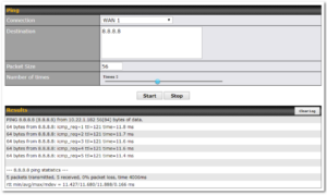
| Tip |
| A system administrator can use the ping utility to manually check the connectivity of a particular LAN/WAN connection. |
Traceroute#
The traceroute test tool traces the routing path to the destination through a particular Ethernet interface or a SpeedFusionTM connection. The traceroute test utility is located at System>Tools>Traceroute.
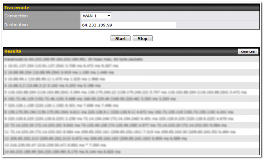
| Tip |
| A system administrator can use the traceroute utility to analyze the connection path of a LAN/WAN connection. |
Wake-on-LAN#
Peplink routers can send special “magic packets” to any client specified from the Web UI. To access this feature, navigate to System > Tools > Wake-on-LAN

Select a client from the drop-down list and click Send to send a “magic packet”
WAN Analysis#
The WAN Analysis feature allows you to run a WAN to WAN speed test between 2 Peplink devices .
You can set a device up as a Server or a Client. One device must be set up as a server to run the speed tests and the server must have a public IP address.
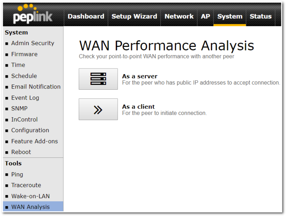
The default port is 6000 and can be changed if required. The IP address of the WAN interface will be shown in the WAN Connection Status section.
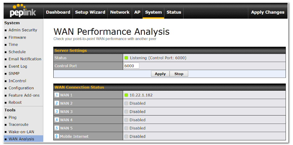
The client side has a few more settings that can be changed. Make sure that the Control Port matches what’s been entered on the server side. Select the WAN(s) that will be used for testing and enter the Servers WAN IP address. Once all of the options have been set, click the Start Test button.
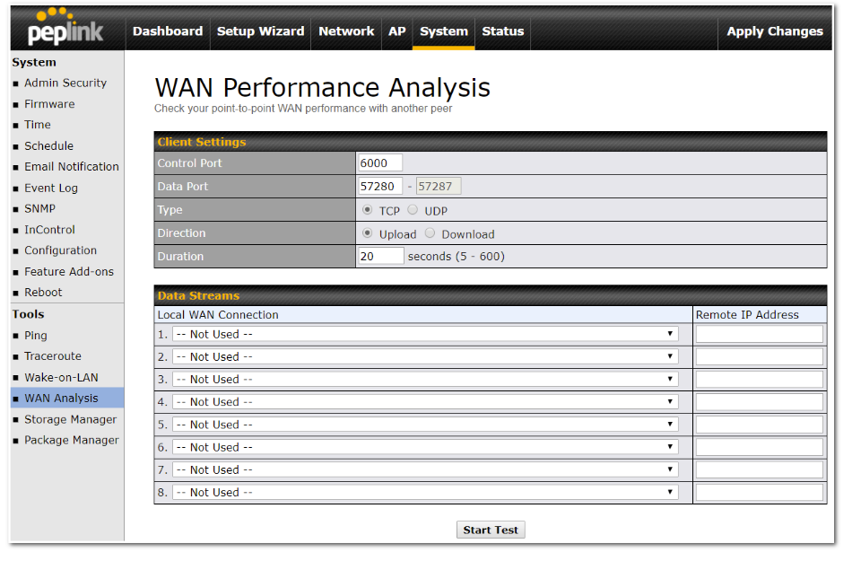
The test output will show the Data Streams Parameters, the Throughput as a graph, and the Results.
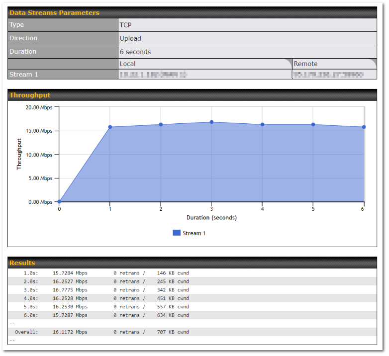
The test can be run again once it’s complete by clicking the Start button or you can click Close and change the parameters for the test.
Storage Manager#
*This page is only available on device with Edge computing features. Kindly refer the link below to further check if the device is able to support edge computing.
https://www.peplink.com/compare/routers/
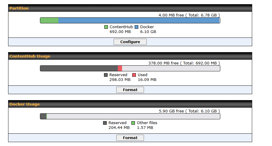
This page allow user to configure or format partition of internal storage for MediaFast / ContentHub / Docker Usage.
External Storage#
(inlcuded in B One user manual – https://manual.peplink.com/peplink-b-one-series-user-manual/#4245)
*This page is only available on device with “External Storage via USB Port”. Kindly refer the link below to further check if the device is able to support External Storage and enable edge computing (Docker).
https://www.peplink.com/compare/routers/

This page allow user to manage their USB storage that connected to the device.
Package Manager#
*This page is only available on device with Edge computing features. Kindly refer the link below to further check if the device is able to support edge computing.
https://www.peplink.com/compare/routers/
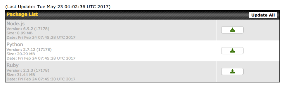
This page allow users to manage supported framework that is needed for ContentHub. For more information on how to upload content to the Content Hub, kindly refer (MAX – Chapter 18, Balance – Chapter 12 > Edge Computing).
CLI (Command Line) Support#
The CLI (Command Line Interface) can be accessed via SSH. You can use it to get device statistics and basic operations.
CLI Connect Method:

CLI (System > Admin Security):
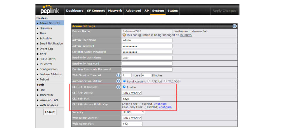
CLI:
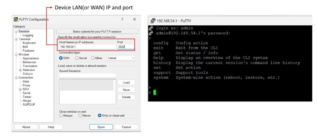
Visit this link for full command set.
Ch16. Status Tab#
Status#
Device#
System information is located at Status>Device.
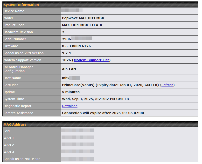
| System Information | |
| Device Name | This is the name specified in the Device Name field located at System > Admin Security. |
| Model | This shows the model name and number of this device. |
| Product Code | If your model uses a product code, it will appear here. |
| Hardware Revision | This shows the hardware version of this device. |
| Serial Number | This shows the serial number of this device. |
| Firmware | This shows the firmware version this device is currently running. |
| Care Plan | Display care plan status and expiry date.
Note: Refresh button to manually refresh the PrimeCare license. User who has disabled InControl management may click [Refresh] option to check the PrimeCare license status after a renewal. |
| SpeedFusion VPN | This shows the current SpeedFusion VPN version. |
| Modem Support Version | This shows the modem support version. For a list of supported modems, click Modem Support List. |
| Host Name | The host name assigned to the Pepwave router appears here. |
| Uptime | This shows the length of time since the device has been rebooted. |
| System Time | This shows the current system time. |
| Diagnostic Report | The Download link is for exporting a diagnostic report file required for system investigation. |
| Remote Assistance | This option is to Turn on remote assistance with the time duration. |
The second table shows the MAC address of each LAN/WAN interface connected. To view your device’s End User License Agreement (EULA), click ![]() Legal.
Legal.
Active Sessions#
Information on active sessions can be found at Status>Active Sessions>Overview.
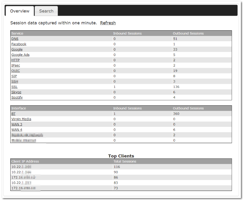
This screen displays the number of sessions initiated by each application. Click on each service listing for additional information. This screen also indicates the number of sessions initiated by each WAN port. Finally, you can see which clients are initiating the most sessions.
In addition, you can also perform a filtered search for specific sessions. You can filter by subnet, port, protocol, and interface. To perform a search, navigate to Status>Active Sessions>Search.
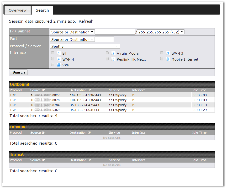
This Active Sessions section displays the active inbound / outbound sessions of each WAN connection on the Peplink Balance. A filter is available to help sort out the active session information. Enter a keyword in the field or check one of the WAN connection boxes for filtering.
Client List#
The client list table is located at Status>Client List. It lists DHCP and online client IP addresses, type, names (retrieved from the DHCP reservation table or defined by users), current download and upload rate, and MAC address.
Clients can be imported into the DHCP reservation table by clicking the ![]() button on the right. Further update the record after the import by going to Network>LAN.
button on the right. Further update the record after the import by going to Network>LAN.
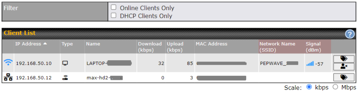
If the PPTP server SpeedFusionTM, or AP controller is enabled, you may see the corresponding connection name listed in the Name field.
In the client list table, there is a “Ban Client” feature which is used to disconnect the Wi-Fi and Remote User Access clients by clicking the ![]() button on the right.
button on the right.
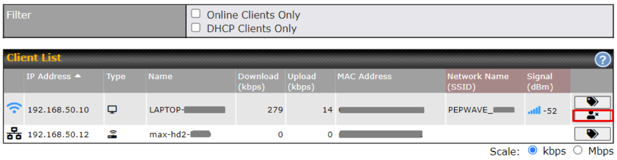
There is a blocklist on the same page after you banned the Wi-Fi or Remote User Access clients.
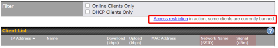
You may also unblock the Wi-Fi or Remote User Access clients when the client devices need to reconnect the network by clicking the ![]() button on the right.
button on the right.
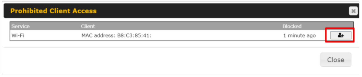
WINS Clients#
The WINS client list table is located at Status>WINS Client.
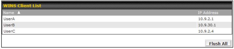
The WINS client table lists the IP addresses and names of WINS clients. This option will only be available when you have enabled the WINS server The names of clients retrieved will be automatically matched into the Client List (see previous section). Click Flush All to flush all WINS client records.
OSPF & RIPv2#
Information on OSPF and RIPv2 routing setup can be found at Status>OSPF & RIPv2.
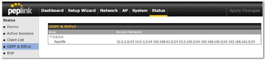
MediaFast#
To get details on storage and bandwidth usage, select Status>MediaFast.
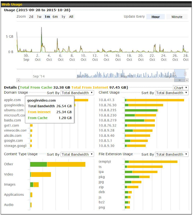
SpeedFusion VPN#
Current SpeedFusion VPN status information is located at Status > SpeedFusion VPN.
Details about SpeedFusion VPN connection peers appear below:
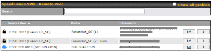
Click on the corresponding peer name to explore the WAN connection(s) status and subnet information of each VPN peer.
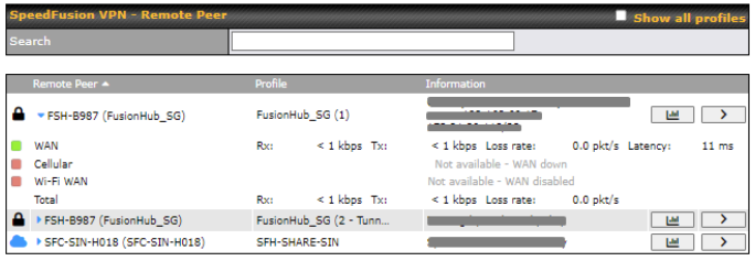
Click the ![]() button for a SpeedFusion chart displaying real-time throughput, latency, and drop-rate information for each WAN connection.
button for a SpeedFusion chart displaying real-time throughput, latency, and drop-rate information for each WAN connection.
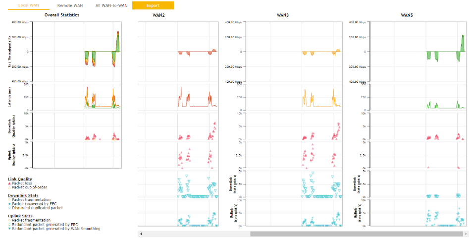
When pressing the ![]() button, the following menu will appear:
button, the following menu will appear:
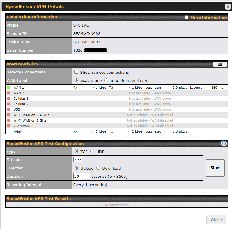
The connection information shows the details of the selected SpeedFusion VPN profile, consisting of the Profile name, Router ID, Router Name, and Serial Number of the remote router.
Advanced features for the SpeedFusion VPN profile will also be shown when the More Information checkbox is selected.
The WAN statistics show information about the local and remote WAN connections (when showing Remote connections) is selected.
The available details are the WAN Name, IP address, and port used for the Speedfusion connection. Rx and Tx rates, Loss rate and, Latency.
Connections can be temporarily disabled by sliding the switch button next to a WAN connection to the left.
The wan-to-wan connection disabled by the switch is temporary and will be re-enabled after 15 minutes without any action.
This can be used when testing the SpeedFusion VPN’s speed between two locations to see if there is interference or network congestion between certain WAN connections.
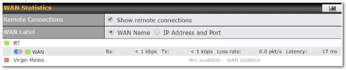
The SpeedFusion VPN test configuration allows us to configure and perform thorough testing.
This is usually done after the initial installation of the routers and when there are aggregation issues.
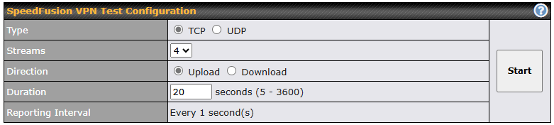
Press the Start button to perform the throughput test according to the configured options.
If TCP is selected, 4 parallel streams will be generated by default to obtain optimal results. This can be customized by selecting a different value of streams.
Duration can be set from a minimum of 5 seconds to a maximum of 3600 seconds. The reporting interval will increase based on the entered duration.
| Duration (seconds) | Reporting Interval (seconds) |
| 5 – 600 | 1 |
| 601 – 1200 | 2 |
| 1201 – 2400 | 5 |
| 2401 – 3600 | 10 |
Using more streams will usually give better results if the latency of the tunnel is high.
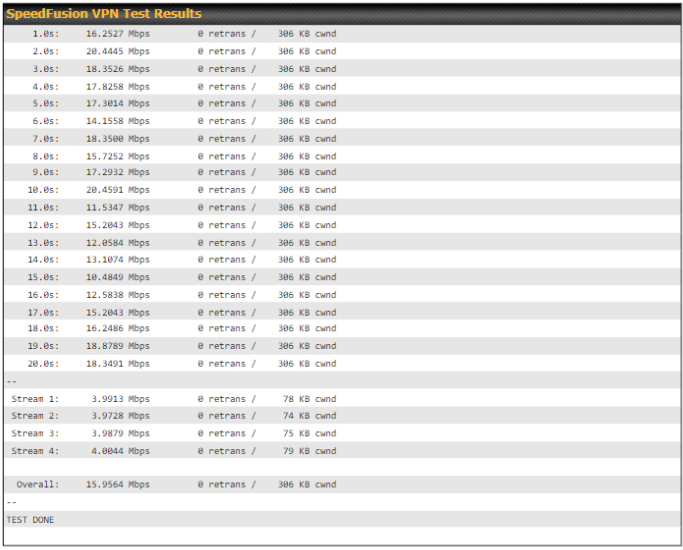
Peplink has also published a white paper on Speedfusion, which can be downloaded from the following URL:
http://download.peplink.com/resources/whitepaper-speedfusion-and-best-practices-2019.pdf
Event Log#
Event log information is located at Status>Event Log.
Device Event Log
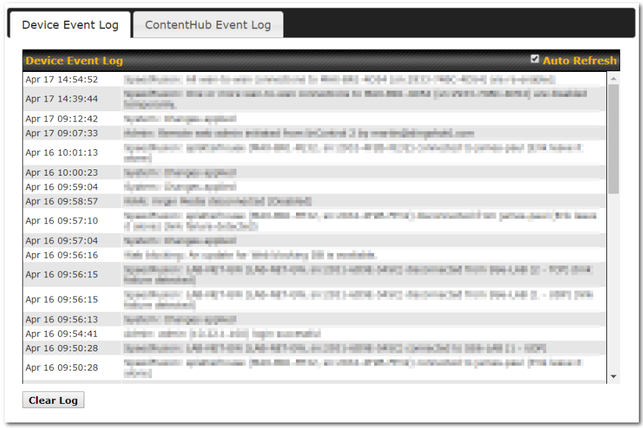
The log section displays a list of events that have taken place on the Peplink Balance unit. Check Auto Refresh to refresh log entries automatically. Click the Clear Log button to clear the log.
IPsec Event Log
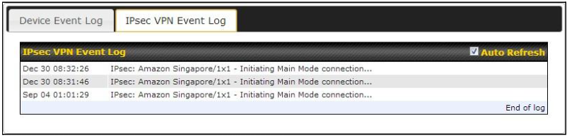
This section displays a list of events that have taken place within an IPsec VPN connection. Check the box next to Auto Refresh and the log will be refreshed automatically.
For an AP event log, navigate to AP > Info.
WAN Quality#
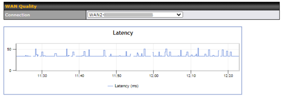
The Status > WAN Quality allows to show detailed information about each connected WAN connection.
Usage Reports#
This section shows the bandwidth usage statistics, located at Status > Bandwidth. Bandwidth usage at the LAN while the device is switched off (e.g., LAN bypass) is neither recorded nor shown.
Real-Time#
The Data transferred since installation table indicates how much network traffic has been processed by the device since the first bootup. The Data transferred since last reboot table indicates how much network traffic has been processed by the device since the last bootup.
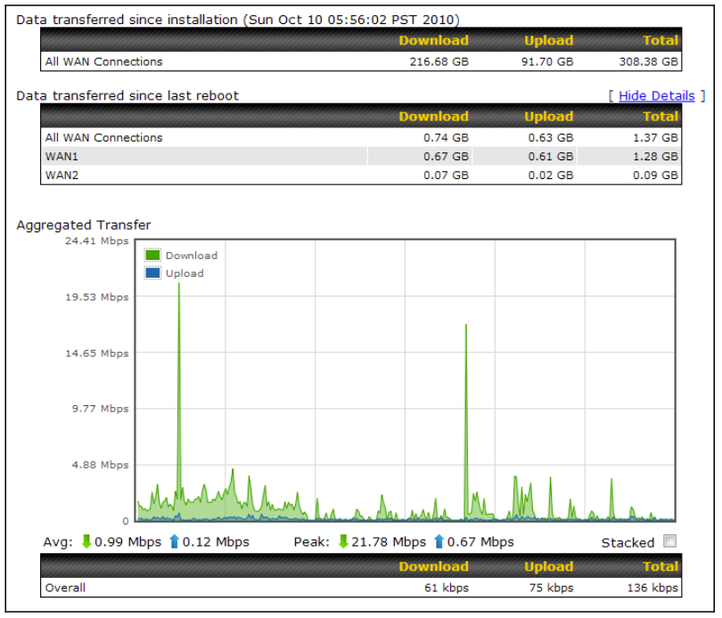
Hourly#
This page shows the hourly bandwidth usage for all WAN connections, with the option of viewing each individual connection. Select the desired connection to check from the drop-down menu.
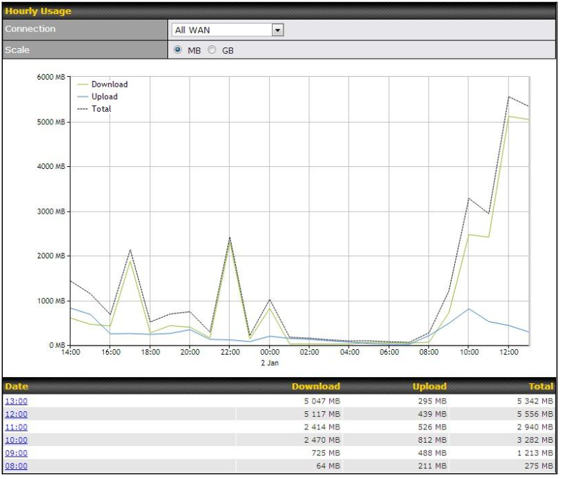
Daily#
This page shows the daily bandwidth usage for all WAN connections, with the option of viewing each individual connection.
Select the connection to check from the drop-down menu. If you have enabled the Bandwidth Monitoring feature as shown in Section 13.4, the Current Billing Cycle table for that WAN connection will be displayed.
Click on a date to view the client bandwidth usage of that specific date. This feature is not available if you have selected to view the bandwidth usage of only a particular WAN connection. The scale of the graph can be set to display megabytes (MB) or gigabytes (GB).
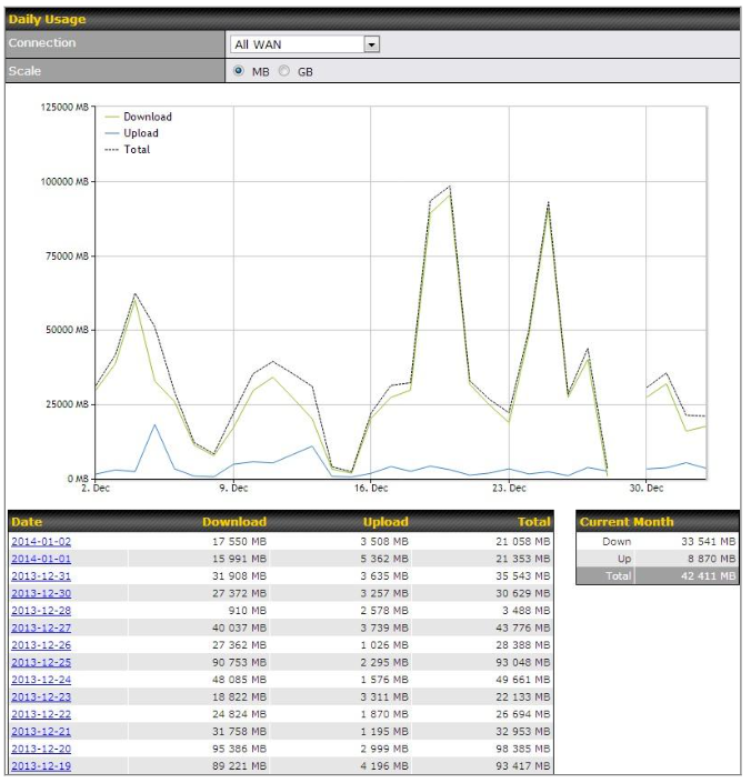
Status
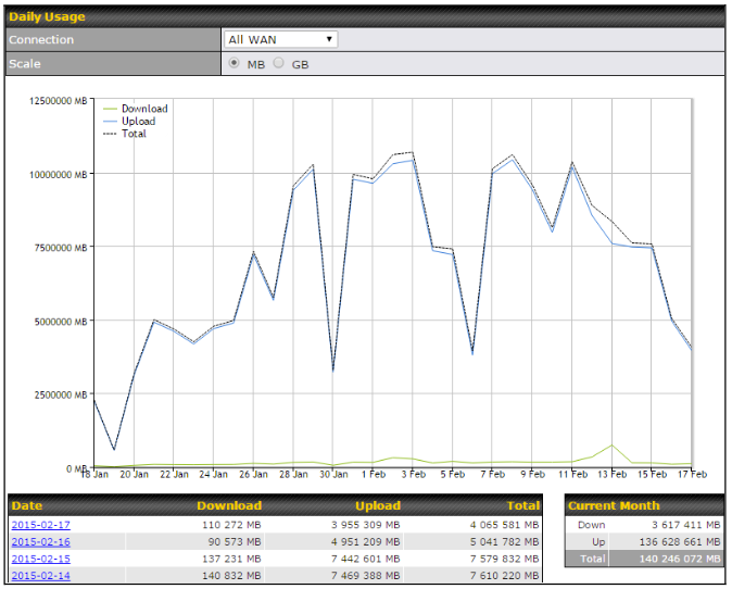
Click on a specific date to receive a breakdown of all client usage for that date.
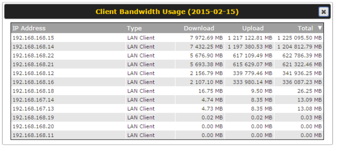
Monthly#
This page shows the monthly bandwidth usage for each WAN connection. If you have enabled Bandwidth Monitoring feature as shown in Section 13.4, you can check the usage of each particular connection and view the information by Billing Cycle or by Calendar Month.
Click the first two rows to view the client bandwidth usage in the last two months. This feature is not available if you have chosen to view the bandwidth of an individual WAN connection. The scale of the graph can be set to display megabytes (MB) or gigabytes (GB).
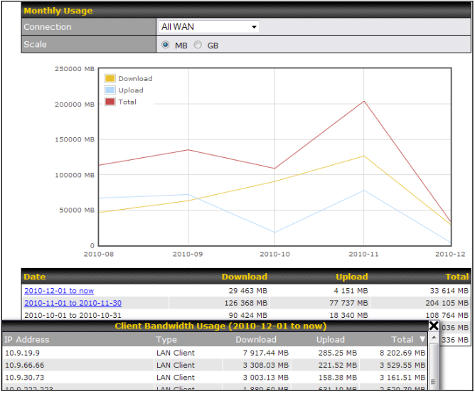
Click on a specific month to receive a breakdown of all client usage for that month.
Appendix List#
Appendix A. Restoration of Factory Defaults
Appendix B. Routing under DHCP, Static IP, and PPPoE
Appendix E. Overview of ports used by Peplink SD-WAN routers and other Peplink services
Appendix B. Routing under DHCP, Static IP, and PPPoE#
Routing under DHCP, Static IP, and PPPoE
The information in this appendix applies only to situations where the Peplink Balance operates a WAN connection under DHCP, Static IP, or PPPoE.
Routing Via Network Address Translation (NAT)
When the Peplink Balance is operating under NAT mode, the source IP addresses of outgoing IP packets are translated to the WAN IP address of the Peplink Balance. With NAT, all LAN devices share the same WAN IP address to access the Internet (i.e., the WAN IP address of the Peplink Balance).
Operating the Peplink Balance in NAT mode requires only one WAN (Internet) IP address. In addition, operating in NAT mode also has security advantages because LAN devices are hidden behind the Peplink Balance. They are not directly accessible from the Internet and hence less vulnerable to attacks.
The following figure shows the packet flow in NAT mode:
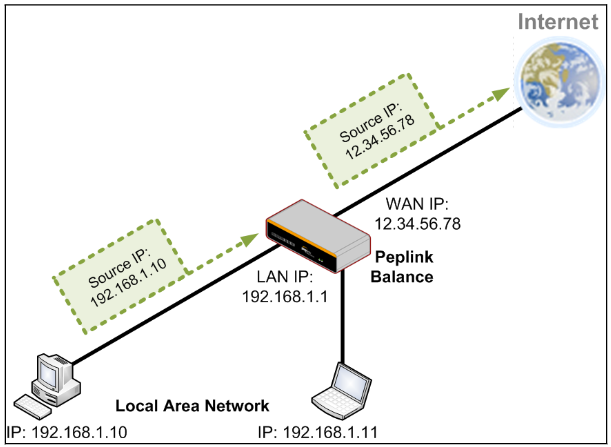
Routing Via IP Forwarding
When the Peplink Balance is operating under IP forwarding mode, the IP addresses of IP packets are unchanged; the Peplink Balance forwards both inbound and outbound IP packets without changing their IP addresses.
The following figure shows the packet flow in IP forwarding mode:
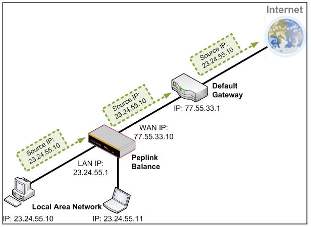
Appendix C. FusionSIM Manual#
Peplink has developed a unique technology called FusionSIM, which allows SIM cards to remotely link to a cellular router. This can be done via cloud or within the same physical network. There are a few key scenarios to fit certain applications.
The purpose of this manual is to provide an introduction on where to start and how to set up for the most common scenarios and uses.
Requirements
- A Cellular router that supports FusionSIM technology
- SIM Injector
- SIM card
Notes:
- Always check for the latest Firmware version for both the cellular router and the SIM Injector. You can also check for the latest Firmware version on the device’s WEB configuration page.
- A list of products that support FusionSIM can be found on the SIM Injector WEB page. Please check under the section Supported models.
SIM Injector reset and login details
How to reset a SIM Injector:
- Hold the reset button for 5-10 seconds. Once the LED status light turns RED, the reset button can be released. SIM Injector will reboot and start with the factory default settings.
The default WEB login settings:
- User: admin
- Password: admin
- IP address: the device only has a DHCP client and no fallback IP address. Therefore, it is advised to check every time what IP address is assigned to the SIM Injector.
Notes:
- The SIM Injector can be monitored via InControl 2. Configuration is not supported.
Scenario 1#
SIM Injector in LAN of Cellular Router
Setup topology
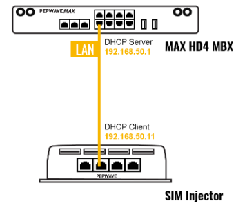
This is the most basic scenario in which the SIM Injector is connected directly to the cellular router’s LAN port via an ethernet cable. This allows for the cellular router to be positioned for the best possible signal. Meanwhile, the SIM cards can be conveniently located in other locations such as the office, passenger area, or the bridge of a ship. The SIM Injector allows for easily swapping SIM cards without needing to access a cellular router.
IMPORTANT: Cellular WAN will not fallback to the local SIM if it is configured to use the SIM Injector.
Configuring the SIM Injector
- Connect the SIM Injector to the LAN port of the cellular router.
- Insert SIM cards into the SIM Injector. The SIM cards will be automatically detected.
IMPORTANT: SIM cards inserted into SIM Injector must not have a PIN code.
Note 1: The SIM Injector gets its IP address via DHCP and doesn’t have a static IP address. To find it’s address, please check the DHCP lease on the cellular router.
Configuring the Cellular Router
Step 1. Enable the SIM Injector communication protocol.
1a. If you are using a Balance cellular router, go to the Network tab (top navigation bar).
1b. If you are using a MAX cellular router, go to the Advanced tab (top navigation bar).
- Under Misc. settings (left navigation bar) find Remote SIM Management.
- In Remote SIM Management, click on the edit icon next to Remote SIM is Disabled.

- Check the Auto LAN discovery checkbox and click Save and Apply Changes.
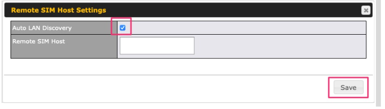
- Click Save and then Apply Changes.
Step 2. Enable RemoteSIM for the selected Cellular interface.
- Go to Network (top navigation bar), then WAN (left navigation bar) and click Details for a selected cellular WAN. This will open the WAN Connection Settings page.
![]()
- Scroll down to Cellular settings.
- In the SIM Card section, select Use Remote SIM Only.
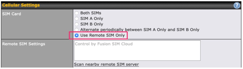
- Enter configuration settings in Remote SIM Settings section. Click on Scan nearby remote SIM server to show the serial number(s) of the connected SIM Injector(s). Available configuration options for cellular interface are shown below:
A. Defining SIM Injector(s)
- Format: <S/N>
- Example 1: 1111-2222-3333
- Example 2: 1111-2222-3333 4444-5555-6666
B. Defining SIM Injector(s) SIM slot(s):
- Format: <S/N:slot number>
- Example 1: 1111-2222-3333:7,5 (the Cellular Interface will use SIM in slot 7, then 5)
- Example 2: 1111-2222-3333:1,2 1111-2222-3333:3,4 (the cellular Interface will use SIM in slot 1, then in 2 from the first SIM Injector, and then it will use 3 and 4 from the second SIM Injector).
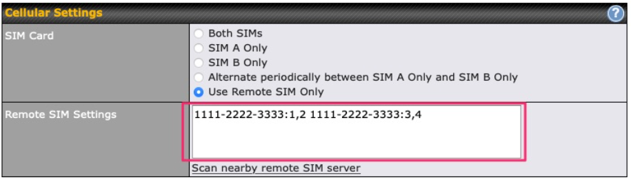
Note: It is recommended to use different SIM slots for each cellular interface.
- Click Save and Apply Changes.
Step 3. (Optional) Custom SIM cards settings.
1a. For a Balance router, go to the Network (Top tab).
1b. For a MAX router, go to the Advanced (Top tab).
- Under Misc. settings (Left-side tab) find Remote SIM Management.
- Click on the Add Remote SIM button, fill in all the required info and click Save. This section allows defining custom requirements for a SIM card located in a certain SIM slot:
- Enable/Disable roaming (by default roaming is disabled).
- Add Custom mobile operator settings (APN, user name, password).
- Repeat configuration for all SIM cards which need custom settings.
- Click Apply Changes to take effect.
Scenario 2#
SIM Injector in WAN of main Router and multiple Cellular Routers
Setup topology
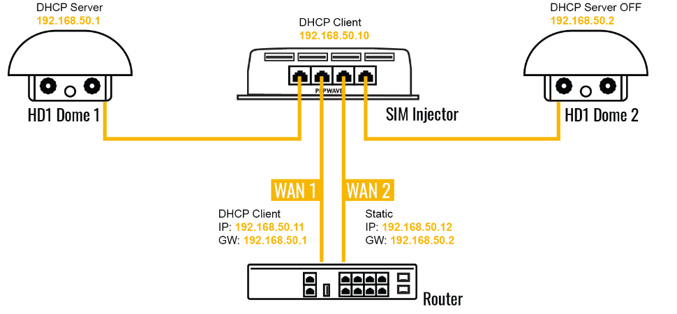
In this scenario, each HD Dome creates a WAN connection to the main router. A single SIM Injector is used to provide SIM cards for each HD Dome. The HD Dome can be replaced with any Peplink cellular router supporting RemoteSIM technology.
This scenario requires the completion of the configuration steps shown in Scenario 1 in addition to the configuration steps explained below.
Additional configurations for Cellular Routers
Step 1. Disable the DHCP server.
- HD Dome 1 should act as a DHCP server.
- HD Dome 2 should be configured to have a static IP address with DHCP disabled.
- Both routers should be in the same subnet (e.g. 192.168.50.1 and 192.168.50.2).
- Go to Network (Top tab), then Network Settings (Left-side tab), and click on Untagged LAN. This will open up the LAN settings page.
- Change the IP address to 192.168.50.2.
- In the DHCP Server section, uncheck the checkbox to disable DHCP Server.
- Click Save and Apply Changes.
Step 2. Ethernet port configuration
The Ethernet port must be set to ACCESS mode for each HD Dome. To do this, dummy VLANs need to be created first.
- Go to Network (Top tab), then Network Settings (Left-side tab), and click on New LAN. This will open the settings page to create a dummy VLAN.
- The image below shows the values that need to be changed to create a new VLAN:
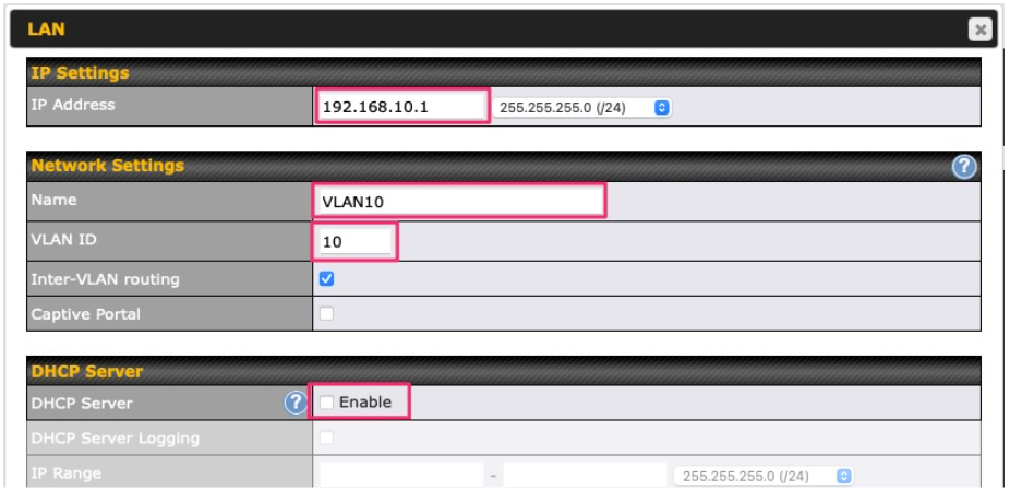 Note: set different IP addresses for each HD dome (e.g. 192.168.10.1 and 192.168.10.2).
 - Click Save and Apply Changes.
- Go to Network (Top tab), then Port Settings (Left-side tab).
- Set the Port Type to Access and set VLAN to Untagged LAN (see picture below).
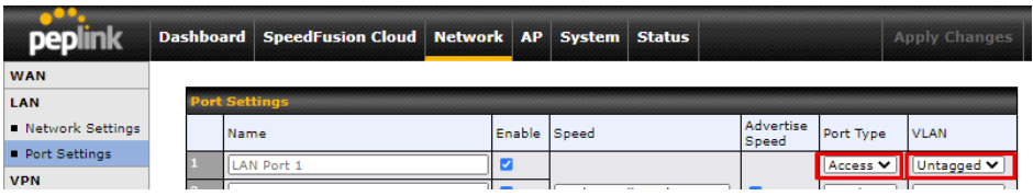
- Click Save and Apply Changes.
Configuration requirements for the main Router
Requirements for the main router are:
- Configure WAN 1 as a DHCP client.
- WAN 1 will automatically get the Gateway IP address from HD Dome 1.
- Configure WAN 2 as a Static IP and set it to 192.168.50.12.
- Configure WAN 2 Gateway to 192.168.50.2. Same as the HD Dome 2’s IP address.
Scenario 3#
SIM Injector in LAN of main Router and multiple Cellular Routers
Setup topology
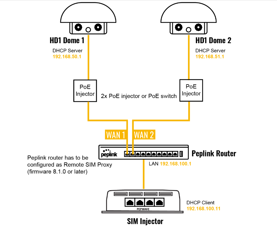
In this scenario, SIMs are provided to the HD Domes via the main router. In this example, the Remote SIM Proxy functionality needs to be enabled on the main router.
Notes:
- HD Dome can be replaced with any other cellular router that supports RemoteSIM.
- It is recommended to use Peplink Balance series or X series routers as the main router.
This scenario requires the completion of the configuration steps for the cellular router and the SIM Injector as in Scenario 1. The configuration for the main router is explained below.
Main Router configuration
IMPORTANT: Main router LAN side and Cellular Routers must be configured using different subnets, e.g. 192.168.50.1/24 and 192.168.100.1/24.
Note: please make sure the Peplink router is running Firmware 8.1.0 or above.
- Open the main router WEB interface and change:
From <IP address>/cgi-bin/MANGA/index.cgi to <IP address>/cgi-bin/MANGA/support.cgi.
This will open the support.cgi page.
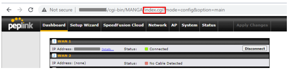
- Scroll down to find Remote SIM Proxy and click on [click to configure] that is located next to it.
- Check the Enable checkbox.
- Click on Save.
- Go back to the index.cgi page and click on Apply Changes.
Scenario 4#
SIM Injector in a remote location
Setup topology
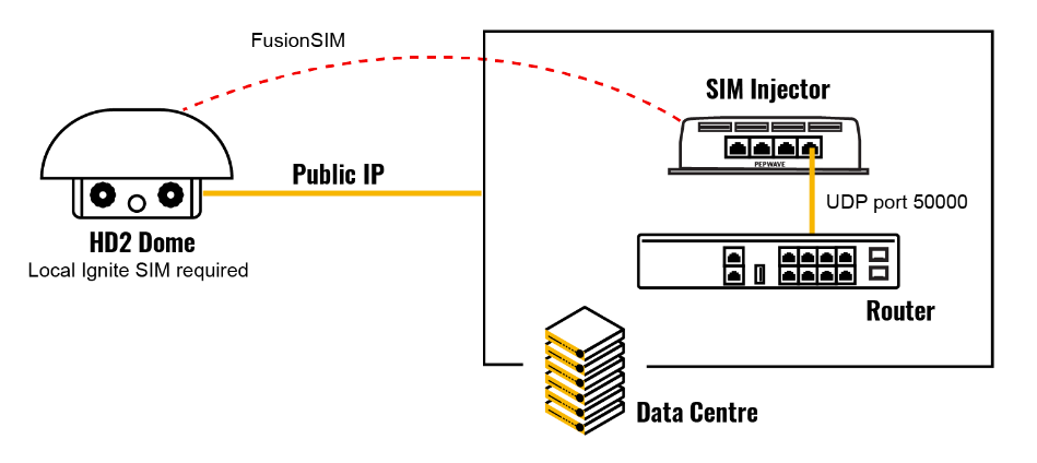
Requirements for installing a SIM Injector in a remote location:
- Cellular router communicates with the SIM Injector via UDP port 50000. Therefore this port must be reachable via public IP over the Internet.
- The one way latency between the cellular router and the SIM Injector should be up to 250 ms. A higher latency may lead to stability issues.
- The cellular router must have Internet connection to connect to the SIM Injector. It can be another Internet connection via Ethernet or Fiber if possible, or a secondary cellular interface with a local SIM (Ignite SIM).
- Due to its high latency, it is not recommended to use satellite WAN for connecting to a SIM Injector in remote locations.
SIM Injector configuration is the same as in Scenario 1.
Cellular Router configuration
Step 1. Enable the SIM Injector communication protocol.
1a. For a Balance cellular router, go to the Network (Top tab).
1b. For a MAX cellular router, go to the Advanced (Top tab).
- Under Misc. settings (Left-side tab), find Remote SIM Management.
- In Remote SIM Management, click on the edit icon next to Remote SIM is Disabled.
- Enter the public IP of the SIM Injector and click Save and Apply Changes.
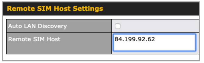
Notes:
- Do NOT check Auto LAN Discovery.
- Adding a SIM Injector serial number to the Remote SIM Host field is a mistake!
Step 2. RemoteSIM and custom SIM card settings configurations are the same as in Scenario 1.
How to check if a Pepwave Cellular Router supports Remote SIM#
- Go to Network (Top tab), then WAN (Left-side tab), and click Details on any cellular WAN. This will open the WAN Connection Settings page.
- Scroll down to Cellular settings.
If you can see the Remote SIM Settings section, then the cellular router supports RemoteSIM.
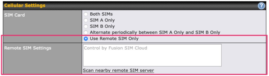
Monitor the status of the Remote SIM#
- Go to Network (Top tab), then WAN (Left-side tab), and click Details on the cellular WAN which was configured to use RemoteSIM.
- Check the WAN Connection Status section. Within the cell WAN details, there is a section for Remote SIM (SIM card IMSI, SIM Injector serial number and SIM slot).
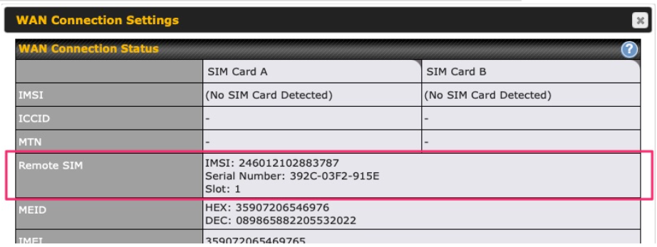
Appendix D. Case studies#
Case studies
MPLS Alternative
Our SpeedFusion enabled routers can be used to bond multiple low-cost/commodity Internet connections to replace an expensive managed business Internet connection, private leased line, MPLS, and frame relay without sacrificing reliability and availability.
Below are typical deployments for using our Balance routers to replace expensive MPLS connections with commodity connections, such as ADSL, 3G, and 4G LTE links.
Special features of Balance 580: have high availability capability
Special features of Balance 2500: have high availability capability and capable of connecting to optical fiber based LAN through SFP+ connector
Our WAN-bonding routers which comprise our Balance series and MediaFast series
are capable of connecting multiple devices, and end users’ networks to the Internet through multiple Internet connections.
Our MediaFast series routers have been helping students at many education institutions to enjoy uninterrupted learning
Option 1: MPLS Supplement#
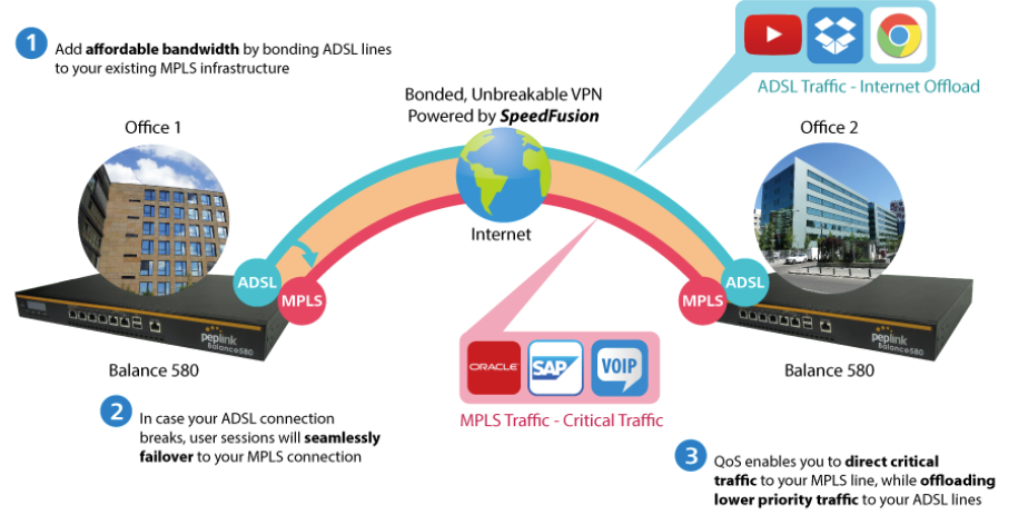
Affordably increase your bandwidth by adding commodity ADSL links to your MPLS connection. SpeedFusion technology bonds all your connections together, enabling session-persistent, user-transparent hot failover. QoS support, bandwidth control, and traffic prioritization gives you total control over your network.
Option 2: MPLS Alternative#
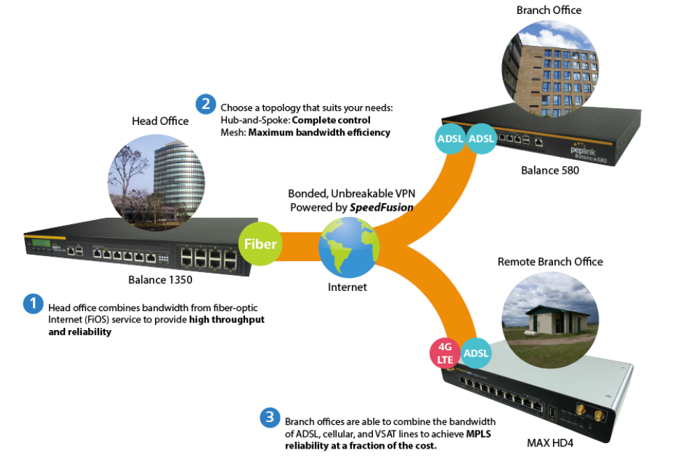
Achieve faster speeds and greater reliability while paying only 20% of MPLS costs by connecting multiple ADSL, 3G, and 4G LTE links. Choose a topology that suits your requirements: a hub-and-spoke topology maximizes control over your network, while a meshed topology can reduce your bandwidth overhead by enabling your devices to form Unbreakable VPN connections directly with each other.
Here is an example of to supplement of existing Multi-Office MPLS network with DSL bonding through SpeedFusion using a Balance 580 at the headquarters and Balance 210/310 at branch offices.
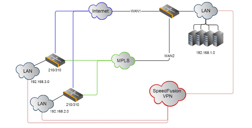
Environment:
- This organization has one head office with two branch offices, with most of the crucial information stored in a server room at the head office.
- They are connecting the offices together using a managed MPLS Solution. However, the MPLS Network is operating at capacity and upgrading the links is cost prohibitive.
- As the organization grows, it needs a cost-efficient way to add more bandwidth to its wide area network.
- Internet access at the remote sites is sent via a web proxy at head office for corporate web filtering compliance.
Requirement:
- User sessions need to remain uninterrupted
- More bandwidth is required at the head office location for direct internet access.
Recommended Solution:
- Form a SpeedFusion tunnel between the branch offices and head office to bond the MPLS and additional DSL lines.
- SpeedFusion allows for hot failover, maintaining a persistent session while switching connections.
- The DSLs at head office can be used for direct internet access providing lots of cheap internet bandwidth.
- Head office can use outbound policies to send internet traffic out over the DSLs and only use the MPLS connection for speedfusion, freeing up bandwidth.
Devices Deployed: Balance 210, Balance 310, Balance 580
Harrington Industrial Plastics#

Overview
Harrington Plastics, the US’s largest industrial plastics distributor, was looking to upgrade its network equipment. Harrington’s team came across Peplink and started thinking about MPLS alternatives. By choosing Peplink, they saved a fortune on upgrades and ended up with yearly savings of up to $100,000.
Requirements
- Zero network outages
- Flexible resilience options
- Cost-effective solution
Solution
- Peplink Balance 1350
- Peplink Balance 380
- Unbreakable VPN
Benefits
- Extreme savings of $100,000 per year
- 4x the bandwidth
- Seamless hardware failover
- Highly available network due to WAN diversity
- Highly cost-effective compared to competing solutions
- Easy resilience achieved by adding 4G USB modems
Time For An Upgrade
Harrington Industrial Plastics decided it was time to upgrade its network equipment. Its existing solution used redundant MPLS for site-to-site traffic and broadband connections for Internet access. Harrington is the US’s largest distributor of industrial plastics piping, serving all industries with corrosive and high-purity applications. It requires peak performance at all times in order to serve its large customer base and 43 busy branches.
Quick Deployment and Unbreakable Connectivity
In evaluating an upgrade to its network infrastructure, it was only natural that Harrington settled on the best in the industry — Peplink. Peplink partner Frontier Computer Corporation was chosen to help design and deploy the solution. Since Peplink gear is so easy to configure and install, Harrington was able to design, prototype and roll out the entire solution to the corporate headquarters and all 43 branches within just one year.
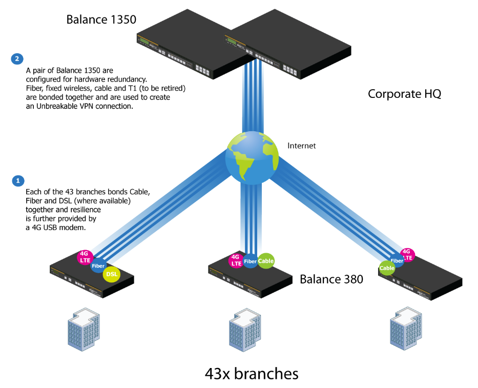
The corporate office houses a pair of redundant Balance 1350s for hardware resilience. Served by 4 separate links from multiple service providers, the network’s chance of an outage is practically zero. All 43 branches are now equipped with a fleet of Balance 380s, bonding a combination of DSL, cable and fiber-optic links together with an additional 4G USB modem for added resilience. These work together to create an Unbreakable VPN connection to the Balance 1350s at the corporate office, connecting the final dot.
Dependable, Resilient Networking that’s also Very Budget-friendly
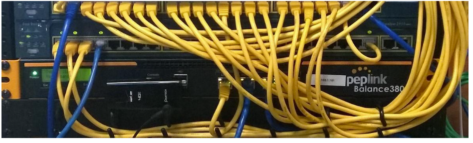
Harrington Industrial Plastics couldn’t be happier. They now benefit from an extremely reliable and cost-effective network. Supplying additional resilience is as easy as plugging in a 4G USB modem. Where the MPLS 768kb deployed previously had cost them $192000 a year for all 40 sites, their new solution is now only costing them $92000. Their total bandwidth has been bumped from 36 Mbps to 138 Mbps.
PLUSS
Peplink + Citrix + VoIP Adds Up to Fast, Cost-Effective WAN for Pluss

A Peplink customer since 2006, Pluss is a social enterprise that each year makes gainful employment a reality for more than 5000 disabled and disadvantaged UK citizens. With 37 locations and 300+ active users, Pluss makes heavy use of its WAN infrastructure, which until recently was built on managed MPLS lines.
Hoping to cut expenses and, if possible, boost performance at the same time, Steve Taylor, IT Manager at Pluss, set out to find a solution that would allow Pluss to replace costly MPLS service with a commodity alternative, such as DSL or EFM.
Steve found the solution Pluss needed in Peplink products, especially the Balance series of high-performance enterprise routers and SpeedFusion bonding technology. Pluss now powers its entire WAN infrastructure with simple-to-install, highly reliable, and cost-effective Peplink gear, which allows it to aggregate DSL and other commodity connections and replace expensive leased lines.
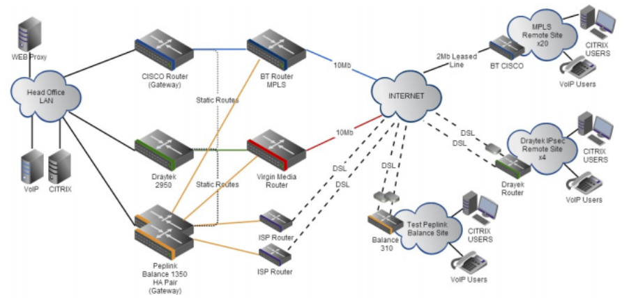
Colégio Next - Enabling eLearning#

Colégio Next, a recognized Apple Distinguished School – deploys over 500 iPads to its 600 students as a teaching and learning tool.
Despite being equipped with iPads, teachers and students alike were not making use of them. The reason for this was because of the slow network access speeds. Apps would not download and course contents were inaccessible. Often, having more than a couple students connected to the same Wi-Fi access point was enough to bring it to its knees.
Colégio Next needed a unique solution, so they contacted Peplink.
Requirements
- Solve network congestion problem caused by 600 students over rural Internet connections
- Wi-Fi that can handle 50+ users per classroom
- An affordable network infrastructure that can provide simultaneous access to media-rich educational content
Solution
- Peplink MediaFast
- Multi-WAN Content-caching router, tailor-made for Education networking.
- AP One 300M
- Enterprise grade AP, 5GHz Wi-Fi, up to 60 concurrent users.
Benefits
- Instant, simultaneous access to media-rich educational content for 500+ iPads
- Wi-Fi connection stability for 50+ users per classroom, not achievable by other tested equipment
- Teachers, students and guests can be assigned access priority to available bandwidth, further preventing congestion
- iOS updates (often 2GB size) no longer congest the network as they are downloaded only once, cached on the MediaFast and then distributed to all iOS devices
- AP Controller makes MAC Address Filtering easy. Students are assigned to designated APs by their devices’ MAC Address in order to prevent saturating any single AP.
- Flawless iPad AirPlay mirroring at all times
- iPads are used all day, reaching their full potential with a fast and stable network all the time
- Students are far more engaged and teachers rely on their iPads all day
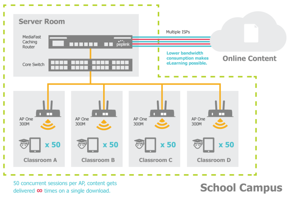
Maintaining the Same IP Address Throughout a Session#
Scenario
Some IP address-sensitive websites (for example, Internet banking) use both client IP address and cookie matching for session identification. Since load balancing uses different IP addresses, the session is dropped when a mismatched IP is detected, resulting in frequent interruptions while visiting such sites.
Solution
Make use of the persistence functionality of the Peplink Balance. With persistence configured and the By Destination option selected, the Peplink Balance will use a consistent WAN connection for source-destination pairs of IP addresses, preventing sessions from being dropped.
With persistence configured and the option By Source is selected, the Peplink Balance uses a consistent WAN connection for same-source IP addresses. This option offers higher application compatibility but may inhibit the load balancing function unless there are many clients using the Internet.
Settings
Set persistence in at Advanced>Outbound Policy.
Click Add Rule, select HTTP (TCP port 80) for web service, and select Persistence. Click Save and then Apply Changes, located at the top right corner, to complete the process.
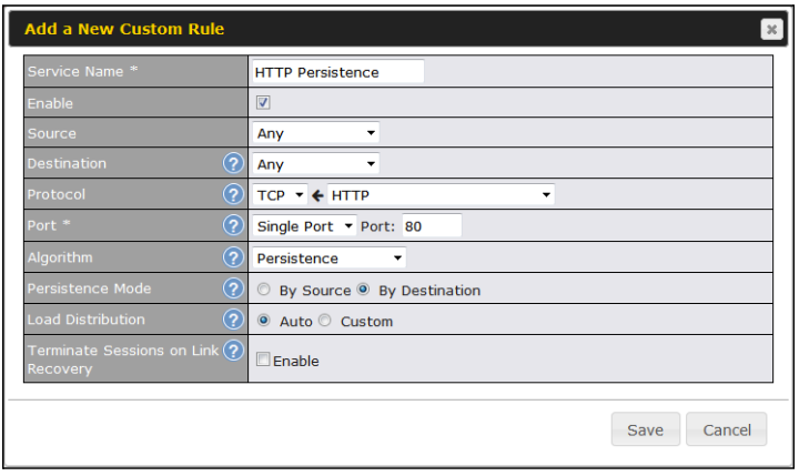
| Tip |
| A network administrator can use the traceroute utility to manually analyze the connection path of a particular WAN connection. |
Bypassing the Firewall to Access Hosts on LAN#
Scenario
There are times when remote access to computers on the LAN is desirable; for example, when hosting web sites, online businesses, FTP download and upload areas, etc. In such cases, it may be appropriate to create an inbound NAT mapping for the network to allow some hosts on the LAN to be accessible from outside of the firewall.
Solution
The web admin interface can be used to add an inbound NAT mapping to a host and to bind the host to the WAN connection(s) of your choice. To begin, navigate to Network>NAT Mappings.
In this example, the host with an IP address of 192.168.1.102 is bound to 10.90.0.75 of WAN1:.
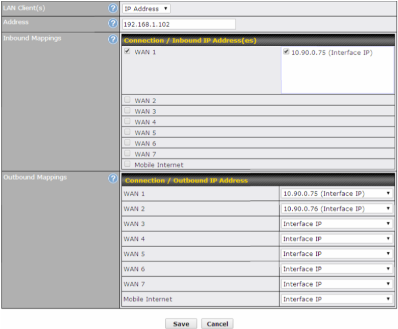
Click Save and then Apply Changes, located at the top right corner, to complete the process.
Inbound Access Restriction#
Scenario
A firewall is required in order to protect the network from potential hacker attacks and other Internet security threats.
Solution
Firewall functionality is built into the Peplink Balance. By default, inbound access is unrestricted. Enabling a basic level of protection involves setting up firewall rules.
For example, in order to protect your private network from external access, you can set up a firewall rule between the Internet and your private network. To do so, navigate to Network>Firewall>Access Rules. Then click the Add Rule button in the Inbound Firewall Rules table and change the settings according to the following screenshot:
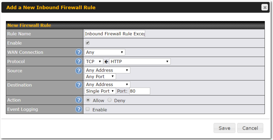
After the fields have been entered as in the screenshot, click Save to add the rule. Afterwards, change the default inbound rule to Deny by clicking the default rule in the Inbound Firewall Rules table. Click Apply Changes on the top right corner to complete the process.
Outbound Access Restriction#
Scenario
For security reasons, it may be appropriate to restrict outbound access. For example, you may want to prevent LAN users from using ftp to transfer files to and from the Internet. This can easily be achieved by setting up an outbound firewall rule with the Peplink Balance.
Solution
To setup a firewall between the Internet and private network for outbound access, navigate to Network>Firewall>Access Rules. Click the Add Rule button in the Outbound Firewall Rules table, and then adjust settings according the screenshot:
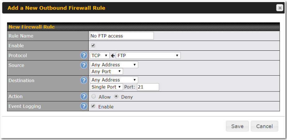
After the fields have been entered as in the screenshot, click Save to add the rule. Click Apply Changes on the top right corner to complete the process.
Appendix H. UK PSTI Statement of Compliance#
For Balance 20X
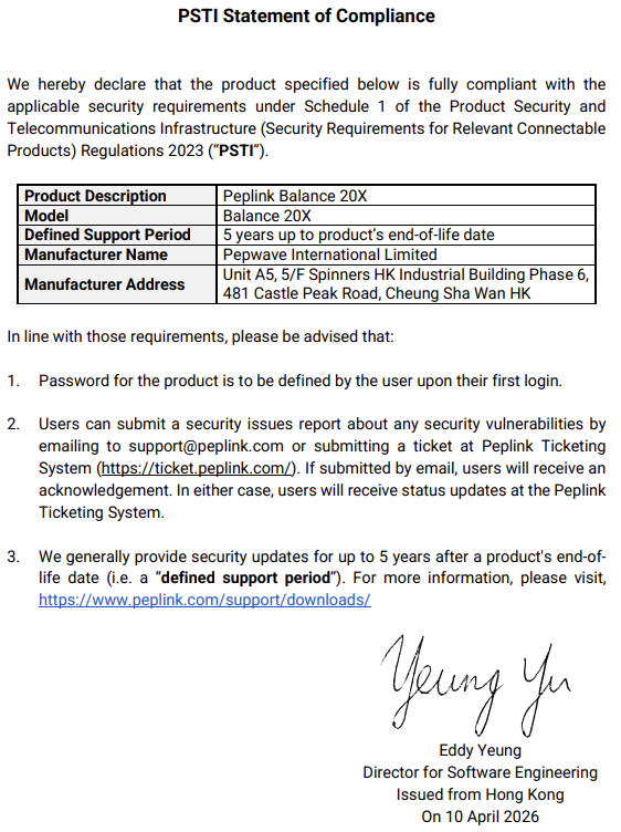
For Balance SDX
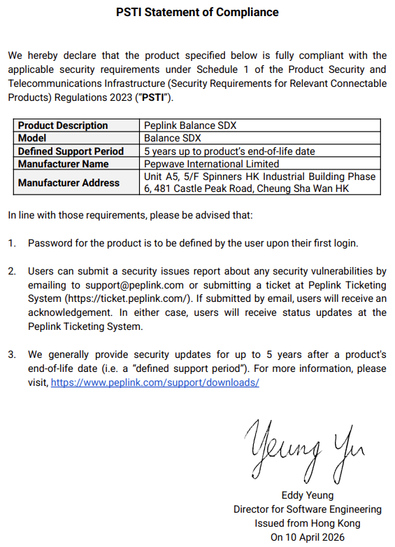
For Balance SDX Pro
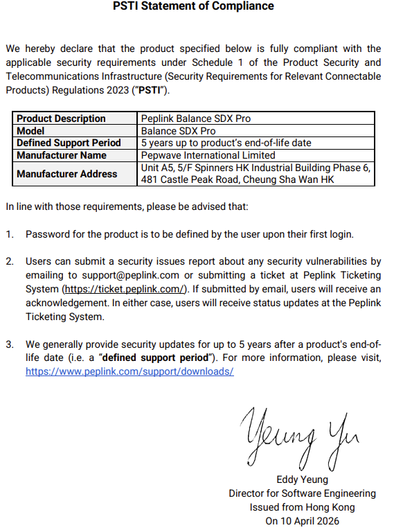
For Balance 380X
For Balance 580X
For Balance 310X

For Balance 310X 5G
For Balance 310 5G

For Balance 310 Fiber 5G
For Balance 2500 EC
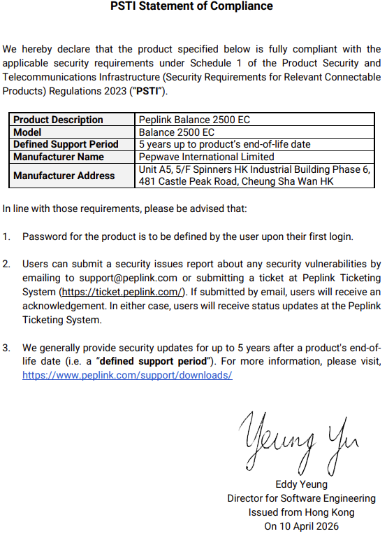
For Balance 710
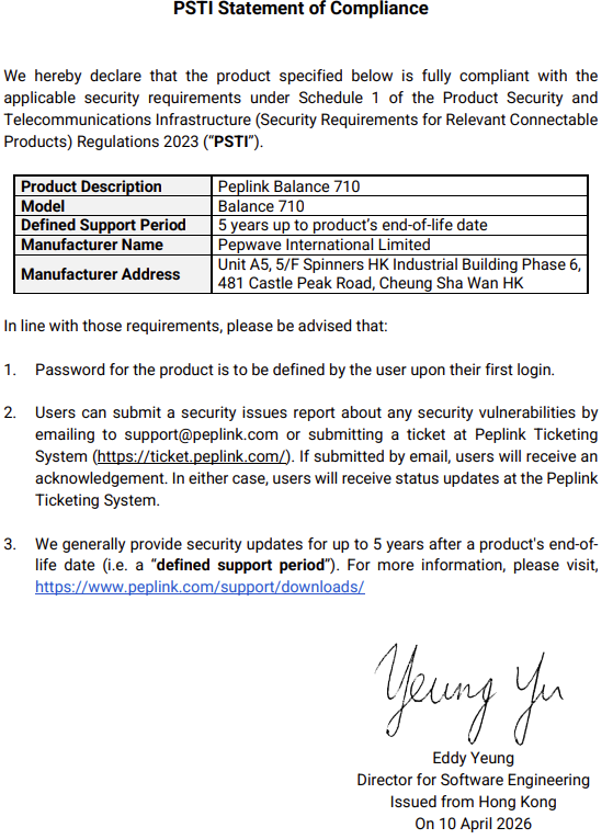
For Balance 5000 EC

For Balance 1350 EC

For EPX
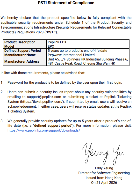
Appendix I. EU Cybersecurity Declaration of Conformity#
For Balance 20X
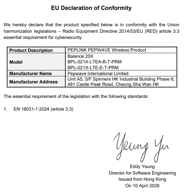
For Balance 20X Pro
For Balance 310X
For Balance 310X 5G
For Balance 310 5G
For Balance 310 Fiber 5G