SpeedFusion Engine Camera-Dockable Quick Start Guide#

SpeedFusion Engine
Camera-Dockable
Quick Start Guide
June 2025
Specifications#
| Specifications | ||
| Cellular WAN Interfaces | Dual LTE-A Modems |  |
| SpeedFusion Hot Failover |
|
|
| SpeedFusion WAN Smoothing |
|
|
| SpeedFusion Bandwidth Bonding |
|
|
| WAN Interface | 1x GE, 1x Wi-Fi WAN* | |
| LAN Interface | 1x GE, 1x USB | |
| Load Balancing/Failover |
|
|
| Router Throughput | 400Mbps | |
| SpeedFusion Throughput (No Encryption) | 100Mbps | |
| SpeedFusion Throughput (256-bit AES) | 60Mbps | |
| Recommended Users | 150 | |
| LTE-A Modem | Downlink/Uplink Data Rate:
300Mbps/50Mbps |
|
| Wi-Fi Standard | 802.11ac | |
| 2.4GHz / 5GHz | 300Mbps / 866Mbps | |
| Simultaneous Wi-Fi WAN & AP |
|
|
| Antennas | Internal | |
| Power Input | DC Adapter: 12 – 24V DC
V-Mount or AntonBauer Battery* rated at: 12.4 – 16.8V DC (max) |
|
| Power Consumption | 18W (max) | |
| Dimensions
(H x W x D) |
10.6 x 5.5 x 4.3 inches
270 x140 x110 mm |
|
Panel Appearance#

Getting Started#
Before connecting the Camera-Dockable SFE to the camera, make sure the camera is switched off. The unit docks directly to camcorders with an Anton Bauer Gold-Mount or V-Mount plate-connectors. The Camera-Dockable SFE is positioned between the camera body and the battery.
Attaching the SFE Cam
Gold Mount
Align the guide pins (x3) with the camera adapter guide hole, and insert them directly. 
Slide the SFE Cam until a “click” sound is heard.
V Mount
Align the V shape with the camera adapter.
Slide the SFE cam until a “click” sound is heard.
Detaching the SFE Cam
Press down the release-lever and slide the SFE Cam toward you to detach it from the camera recorder.
Inserting SIM cards
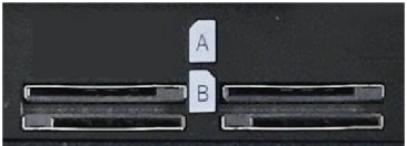
There are a total of 4 SIM slots in the SFE.
SIM slots A1, A2, B1 and B2.
The SFE cam contains 2 cellular SIM modules, each capable of having 1 active SIM and 1 redundant SIM. This means that 2 of the 4 SIMs can be active at the same time.
By default SIM slots A1 and A2 will be used, SIM slots B1 and B2 contain backup SIMs that will be used when there is no connection on SIM A1 and A2.
Standard SIM cards size is supported is (15 x 25mm) and inserted according to the icons shown on the camera.
Connecting the LAN Cable
The SFE plugs into the camera’s USB or LAN port from the matching ports on the SFE using an RJ45 ethernet cable or Mini-DIN jack to USBcable respectively.
The Mini-DIN Jack to USB cable is included with the SFE Cam.
Connecting the WAN cable
The WAN port can be connected to any RJ45 ethernet port to connect to the internet.
Connecting to the SFE Cam Web Admin Interface#
There are 2 methods to configure and monitor your Peplink appliances once they have a WAN connectivity.
- InControl2, Peplinks’ cloud based device management, monitoring, and reporting tool.
- The local web interface
Using InControl#
After logging on to https://incontrol2.peplink.com/ select the desired organization and group and add your device.
The device is now configurable from InControl2.
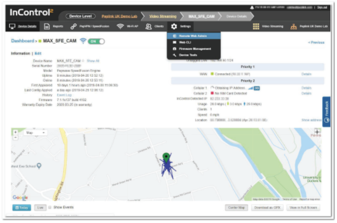
Use the Device > Settings > Remote Admin option to connect to the SFE Cam web admin interface. For more information on InControl2, please download the InControl 2 User guide.
Using the Web admin Interface#
- Start a web browser on a computer that is connected with the SFE Cam through the LAN port.
- To initially connect to the SFE Cam’s web admin interface, enter the following LAN IP address in the address field of the web browser: http://192.168.50.1

- Enter the following to access the web admin interface.
- Username: admin
- Password: admin
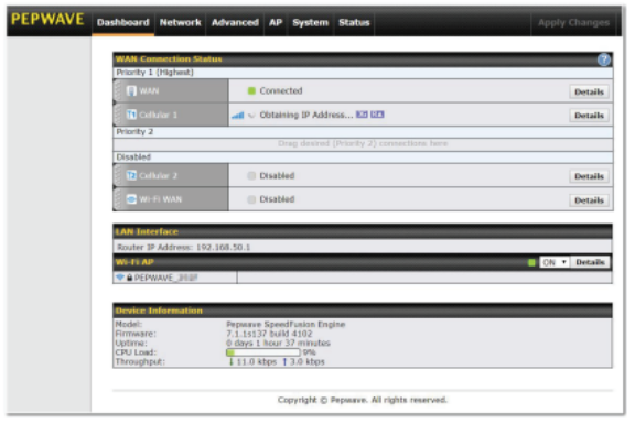
- After successful login, the Dashboard will be displayed
SFE Cam Security#
There are several options to secure your SFE Cam, all of which are accessible by navigating to the System > Admin Security page of the web interface.

1. Change Your Admin Password
For security reasons, after logging in to the web admin Interface for the first time, it is recommended to change the administrator password.
2.Change protocol and port
Change security to HTTPS only, and change Web Admin Access to restrict access from the LAN only. The Web Admin Port can be changed to a non-default port.
3.WAN connection Access settings
If WAN access is required this option allows you to access the web admin interface from certain IP subnets only.
Note: Be aware that once you “Apply Changes” you might lose access to the Web Interface. And you will need to login again using the allowed protocol, port and admin credentials.
For further information on securing your SFE Cam, please read this knowledge base artitle.
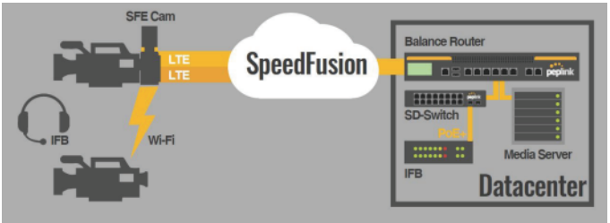
Configuring SpeedFusion VPN#
The SpeedFusion Engine Cam (SFE Cam) uses SpeedFusion bandwidth bonding technology to combine several WAN connections.
SpeedFusion technology needs at least two SpeedFusion devices/peers to work.
This can be another physical Peplink router or a Fusionhub virtual router.
The following example shows how to set up a speedfusion connection between a SFE Cam and a Fusionhub. This process is the same for any Peplink router. SpeedFusion profiles can be configured using InControl or the local web admin interface.
Before you can configure a SpeedFusion profile, one of the routers needs to have at least 1 static public ip address.
The LAN subnet of the connected devices should not overlap. If the same IP range is used reconfigure the LAN settings on one of the devices.
There are too many different options to discuss in this quick start manual; for additional information follow the links in the Additional Resources section at the end of this manual.
Using InControl#
Navigate to the InControl Organization and Group containing your SFE Cam.
Make sure PepVPN /SpeedFusion configuration is enabled in the group settings.
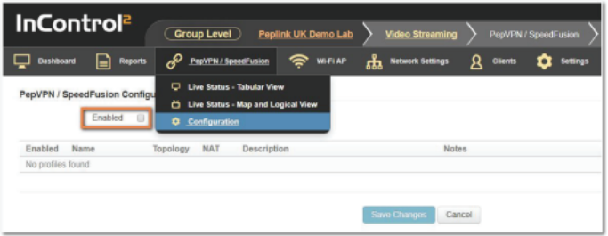
If not enabled already, tick the checkbox and s Save any Changes you make in the process.
![]()
Add Profile.
Choose Star Topology

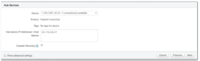
Select the Hub Device included in this VPN tunnel (this is the remote Peplink, NOT the SFE Cam) and click next.
Select the SFE Cam as the End Point device and click next.

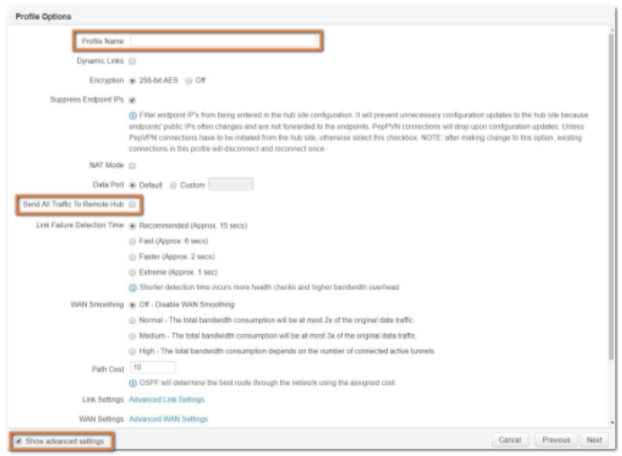
Give the profile an identifiable name, tick the check box with the “Send all Traffic to Remote Hub”, tick the check box for the Advanced settings click next.
Note: The “Send all traffic to Remote Hub” option forces all the data from the SFE Cam to be sent through the SpeedFusion tunnel.
If the traffic would have a local breakout to the internet (ie, not through the SpeedFusion tunnel) cellular bonding would not be effective.
The profile summary shows the configured settings; if these are correct click Finish.

Select Save Changes to make the changes permanent.

After a short time the SpeedFusion tunnel should be established.

The SFE Cam is now ready to start streaming video from the connected camera to the data centre.
Using the web admin Interface#
Take note of the external IP addresses used for both devices (this is the IP address of your WAN connection).
The easiest way to find this is by verifying the InControl detected IP address in Device Details using InControl.

Open the local web admin interface of both Peplink devices in your internet browser. Select Advanced >SpeedFusion on you SFE Cam (Network >SpeedFusion on Peplink devices).
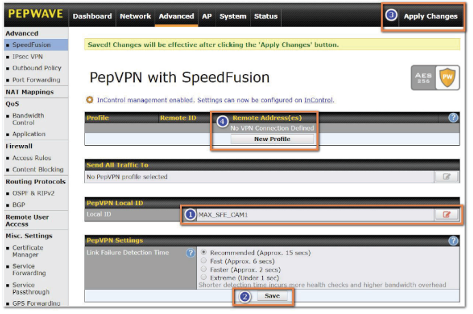
- Edit the PepVPN Local ID to a recognizable, unique Local ID in your network.
- Save the changes.
- Apply the change (Changes will be effective after clicking the ‘Apply Changes’ button).
- After the above changes have been applied on both devices select New Profile on the local web admin interface of the SFE Cam.

In the PepVPN Profile window that appears complete the following details:
- Name (This can be any chosen Name)
- Remote ID (The Local ID of the router that you are connecting to)
- The WAN IP address of the remote router
Select Save and Apply changes.
Follow the same steps on the remote router (the Remote IP address is required to establish the SpeedFusion VPN tunnel).
The SpeedFusion Status on the dashboard will change from Starting > Establishing Tunnel > Updating routes to Established.
Finally, make sure all the traffic from the SFE Cam will be sent through the SpeedFusion VPN tunnel by selecting “Send all traffic to” in Advanced > SpeedFusion

Select the correct SpeedFusion profile in the window that pops up and Save and Apply the changes.

Advanced SpeedFusion Options#
There are many different advanced SpeedFusion features, to overcome problems and /or improve the connection quality and speed of a SpeedFusion tunnel.
When using multiple bonded cellular connections on the SFE Cam we advise to configure the following settings which will improve the connection in most situations.
Use these options after the initial configuration
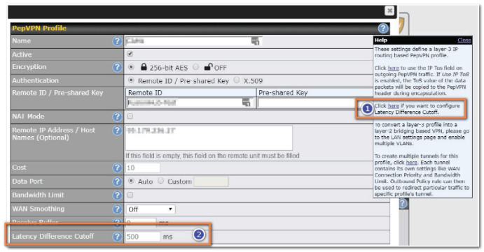
Latency Difference Cutoff
This option can be enabled in the Help section of the SpeedFusion profile (the question mark). This adds another filed to the PepVPN profile when enabled.
Traffic will be stopped briefly for WAN connections that exceed the specified millisecond value with respect to the lowest latency link.
For example: If the Lowest latency is 100ms, a value of 150 ms means links with latency 250 ms or more will not be used).
Start with setting this to 150ms; change the setting depending on measured latency of the WAN connections.
Suspension Time after Packet Loss (ms)
A common issue when using cellular WAN is packet loss.
In most WAN connections we want to stop using this particular WAN connection when there is Packet loss. The default setting to suspend the WAN connection on pepwave routers is 50 ms.
To avoid suspending the cellular connection at all set the value in this field to 0 ms.
Receive Buffer
While the first option should be configured on the SpeedFusion profile of the SFE Cam, the receive buffer should be configured on the remote Speedfusion profile (the “receiving” end).
Receive Buffer can help to reduce out-of-order packets and minimize jitter, but will introduce extra latency to the tunnel.
The buffer size is 0 ms by default, which disables the buffer, and the maximum buffer size is 2000 ms
Note: Disable this option when running PepVPN tests; the receive buffer will make the PepVPN test speeds inaccurate by buffering the data for up to 2 seconds.
WAN Smoothing
WAN smoothing is useful for situations where improving consistency is more important than improving bandwidth.WAN Smoothing is only needed when there are problems with video streaming (packet drop, jitter).
This feature will assign traffic to the WAN connection with the lowest latency.
Instead of using 1 packet, it will send packets over 2 or more WAN connections and only the packets that arrive first will be used (other packets get discarded).
Thus, the latency of the SpeedFusion tunnel becomes the latency of the most responsive WAN connection.
Useful for deployments where improving consistency is more important than improving bandwidth. WAN smoothing has an overhead of at least 50%.
| WAN Smoothing | |
| OFF | 1 packet will be transferred using 1 tunnel. |
| Normal | 2 duplicate packets will be transferred using 2 different tunnels. |
| Medium | 3 duplicate packets will be carried using 3 different tunnels. |
| High | The amount of duplicate packets used is based on the available tunnels. |
Forward Error Correction
When there isn’t enough bandwidth available WAN smoothing can’t be used.because of the overhead of at least 50%.
Peplink has therefore introduced Forward Error Correction.
The effect of Forward Error Correction is similar to WAN smoothing but it consumes less data.
Forward error correction (FEC) is a digital signal processing technique used to enhance data reliability. It does this by introducing redundant data, called error correcting code, prior to data transmission or storage. FEC provides the receiver with the ability to correct errors without a reverse channel to request the retransmission of data. It is required that the peer router is using.
In the web admin interface go to Advanced > SpeedFusion on your SFE Cam.
Select a “New Profile” or open an existing PepVPN profile.
Select the option of choice on the Forward Error Correction drop-down list.
Save and Apply the changes.
The options are:
| Forward Error Correction | |
| Off | Default |
| Low | Expected Overhead 13.3% |
| High | Expected Overhead 26.7% |

Advanced Cellular WAN Options#
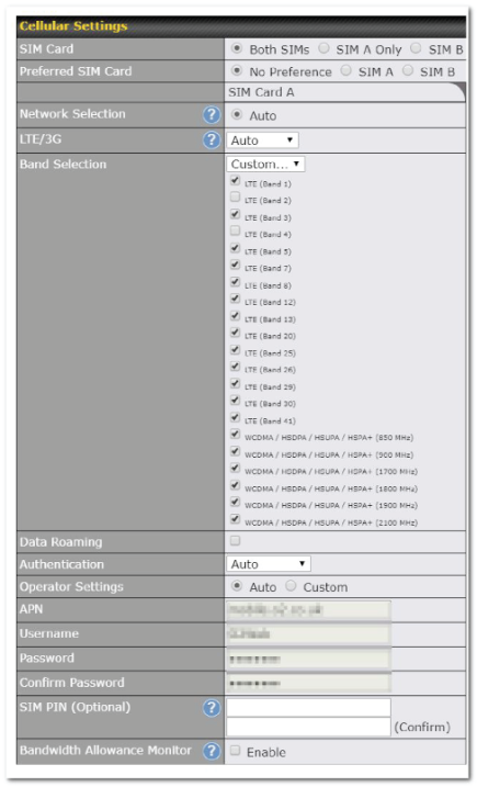
To avoid problems with using Cellular WAN connections we recommend the following.
- If possible, use SIMs from different cellular providers for greater redundancy
- When using SIMs from the same provider, configure the Cellular WAN to use different bands (frequencies) by selecting the bands manually.
Testing Efficiency#
The SFE Cam has several tools built-in to test the throughput of your WAN connection and SpeedFusion VPN.
Wan Performance Analysis
WAN Analysis allows you to run a WAN to WAN speed test.
You need 2 Peplink devices.
You’ll have the option of setting a device up as a Server or a Client and therefore need 2 Peplink devices to do this.
One device must be set up as a server to run the tests and the server must have a public IP address. This is done from the UI under the System > WAN Analysis tab.

The default port is 6000 and can be changed if required.
The IP address of the WAN interface will be shown in the WAN Connection Status section.

The client side has a few more settings that can be changed.
Make sure that the Control Port matches what’s been entered on the server side.
Select the WAN(s) that will be used for testing and enter the Servers WAN IP address. Once all of the options have been set, click the Start Test button.

The test output will show the Data Streams Parameters, the Throughput as a graph, and the Results.

The test can be run again once it’s complete by clicking the Start button or you can click Close and change the parameters for another test.
The PepVPN test is completely rewritten since firmware 7.1. making it far more versatile than it was. You can now show remote connections, and enable and disable these connections to run different tests to see which combinations of connections are the ideal combination for the SpeedFusion tunnel. This shows the real point to point speed from one end of the tunnel to the other, unlike regular speed test which shows the speed from your router to a Speedtest server in a location near you.
Once we established which WAN connections perform best (up- and download speed) we’ll have a look at the Advanced Settings in the Speedfusion profile that can be enabled when selecting the question marks.
PepVPN Test
The PepVPN Tests allow you to check the general TCP/UDP throughput within the SpeedFusion VPN tunnel.
Open Status > Speedfusion in the web interface.
Select the button net to a PepVPN profile to test the PepVPN connection.

A new window showing the PepVPN Connection information will pop up.
When the check box is selected Remote connections are shown as well as the local WA connections. A slider allows you to temporary disable a WAN connection to run tests on individual links and easily assist in finding the best performing combination of WAN connections.

Run a test and see the test result after configuring the desired options.

Mobile Wireless Hub#

With its Wi-Fi radio, the SFE Cam can turn your IP camera into a portable hotspot with VPN access to headquarters.
You can use this hotspot to connect laptops to begin post-processing, or even connect another IP camera for video streaming.
The options to configure a wireless hotspot can be found in InControl or on the local Web Admin Interface in the AP section.
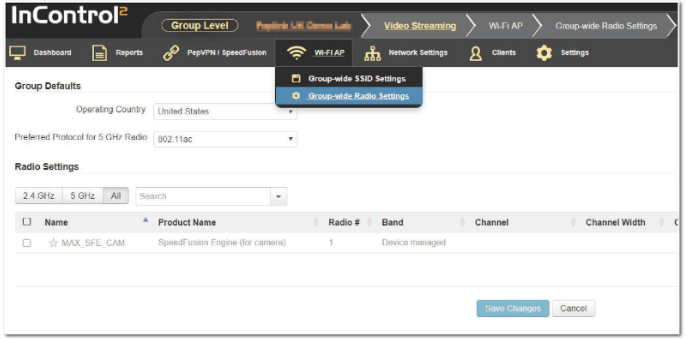
Configure Wi-Fi AP in InControl

Open the Wi-FI AP group settings and select Group-wide SSID settings.
Make sure the Wi-Fi Management Check box is ticked and select Add New SSID.
InControl is built to be self intuitive, complete the empty fields and save the settings.

Select Group-wide Radio Settings to configure the required settings for the 2.4 radios and 5 GHz radios.
Configure Wi-Fi AP using the local web admin interface
In the web admin interface select AP > Settings

Choose the Operating country, other options may be changed when required, but the default options will suffice for most configurations.
Don’t forget to save and apply the changes.
Additionally, configure a Wireless SSID.
A SSID already exists in the default configuration.

Open that SSID profile by selecting it and change the required parameters.
Save and Apply the changes.
Other devices can now establish a secure connection to the main datacenter by connecting to the SSID that is published from the SFE Cam.
Additional Resources#
More detailed instructions for Pepwave devices can be found in the Pepwave Max User Manual
Peplink has an active forum where Peplink Users discuss deployments and problems.
Experienced Peplink users are on hand to answer any questions.
The Peplink website contains general information about Peplink SD-WAN routers and provides links to Peplin partners and distributors and contact details in case you have a problem with your device.
Ethernet Cables
We recommend that you use a shielded cable to connect the Ethernet ports for the network.
FCC Requirements for Operation in the United States
Federal Communications Commission (FCC) Compliance Notice:
Federal Communication Commission Interference Statement
This equipment has been tested and found to comply with the limits for a Class A digital device, pursuant to Part 15 of the FCC Rules. These limits are designed to provide reasonable protection against harmful interference when the equipment is operated in a commercial environment. This equipment generates, uses, and can radiate radio frequency energy, and if it is not installed and used in accordance with the instruction manual, it may cause harmful interference to radio communications. Operation of this equipment in a residential area is likely to cause harmful interference, in which case the user will be required to correct the interference at his own expense.
Any changes or modifications not expressly approved by the party responsible for compliance could void your authority to operate the equipment.
Radiation Exposure Statement
This equipment complies with FCC RF radiation exposure limits set forth for an uncontrolled environment. This equipment should be installed and operated with a minimum distance of 20 centimeters between the radiator and your body.
Battery Caution Statement
Risk of explosion if the battery replaced by an incorrect type, place the battery into fire, a hot oven, extremely high temperature or low air pressure surrounding environment, the leakage of flammable liquid or gas, and mechanically crushing or cutting of the battery.
CE Statement for Pepwave Routers ( SpeedFusion Engine )

2.4GHz ( 2412 – 2472 MHz ) : 19.93 dBm
5GHz ( 5150 – 5250 MHz ) : 22.78 dBm
WWAN : Refer 3GPP TS 36.521 -1 ( UE Power class )
MC7455 module:

This equipment complies with CE radiation exposure limits set forth for an uncontrolled envi- ronment. This equipment should be installed and operated with a minimum distance of 20cm between the radiator & your body.
This equipment is restricted to indoor use only when operating in the 5150 to 5250 MHz frequency range in above countries.
contact as: https://www.peplink.com/