Peplink Switch Series Manual#
Peplink Products:
8 PoE 10G Switch / 24 PoE 2.5G Switch Rugged / 24 PoE 2.5G Switch / 48 PoE 2.5G Switch
Version 1.0.0
December 2025
Models & Specifications#
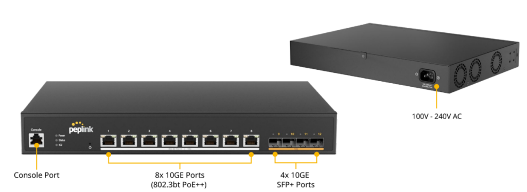
8 PoE 10G Switch#
LED Indicators:
| Status Indicators | ||
| Power | OFF | No power |
| Green (Solid light) | System boot on-going | |
| Green (Solid light) | System boot ready | |
| Status | OFF | System boot on-going / System off |
| Green (Solid light) | System boot ready | |
| IC2 | OFF | No link with IC2 |
| Green (Solid light) | IC2 connected | |
| Ethernet Ports | ||
| RJ45 Left LED (Activity) | OFF | Port is not connected |
| Amber ( Blinking) | Data is transferring | |
| Amber (Solid Light) | Port is connected | |
| RJ45 Right LED (PoE Switch) | Off | PoE disable |
| Green (Solid Light) | PoE Enable (even no cable is connected) | |
| RJ45 Right LED (PoE Switch) | Off | Other speed / No link |
| Green (Solid light) | Highest speed | |
| SFP Ports | ||
| SFP LED (Activity) | Off | No link |
| Green (Blinking) | Activity | |
| Green (Solid light) | Link | |
| Reset Button | ||
| Hold reset button | 0 – 10 seconds | Status light (green) blinking slowly. |
| 10 -15 seconds | Status light (green) blinking fast | |
| Over 15 seconds | Status light off, release reset button and device start reboot. | |
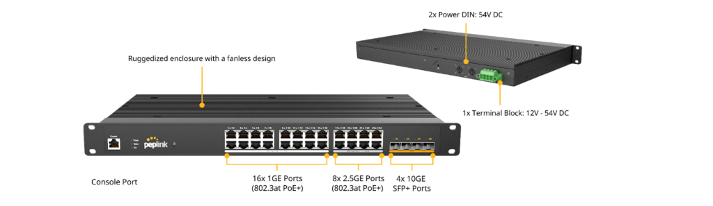
24 PoE 2.5G Switch Rugged#
LED Indicators:
| Status Indicators | ||
| Power | OFF | No power |
| Green (Solid light) | System boot on-going | |
| Green (Solid light) | System boot ready | |
| Status | OFF | System boot on-going / System off |
| Green (Solid light) | System boot ready | |
| IC2 | OFF | No link with IC2 |
| Green (Solid light) | IC2 connected | |
| Ethernet Ports | ||
| RJ45 Left LED (Activity) | OFF | Port is not connected |
| Amber ( Blinking) | Data is transferring | |
| Amber (Solid Light) | Port is connected | |
| RJ45 Right LED (PoE Switch) | Off | PoE disable |
| Green (Solid Light) | PoE Enable (even no cable is connected) | |
| RJ45 Right LED (PoE Switch) | Off | Other speed / No link |
| Green (Solid Light) | Highest speed | |
| SFP Ports | ||
| SFP LED (Activity) | Off | No link |
| Green (Blinking) | Activity | |
| Green (Solid light) | Link | |
| Reset Button | ||
| Hold reset button | 0 – 10 seconds | Status light (green) blinking slowly. |
| 10 -15 seconds | Status light (green) blinking fast | |
| Over 15 seconds | Status light off, release reset button and device start reboot. | |
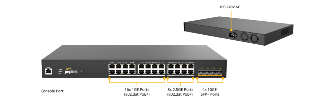
24 PoE 2.5G Switch#
LED Indicators:
| Status Indicators | ||
| Power | OFF | No power |
| Green (Solid light) | System boot on-going | |
| Green (Solid light) | System boot ready | |
| Status | OFF | System boot on-going / System off |
| Green (Solid light) | System boot ready | |
| IC2 | OFF | No link with IC2 |
| Green (Solid light) | IC2 connected | |
| Ethernet Ports | ||
| RJ45 Left LED (Activity) | OFF | Port is not connected |
| Amber ( Blinking) | Data is transferring | |
| Amber (Solid Light) | Port is connected | |
| RJ45 Right LED (PoE Switch) | Off | PoE disable |
| Green (Solid Light) | PoE Enable (even no cable is connected) | |
| RJ45 Right LED (PoE Switch) | Off | Other speed / No link |
| Green (Solid Light) | Highest speed | |
| SFP Ports | ||
| SFP LED (Activity) | Off | No link |
| Green (Blinking) | Activity | |
| Green (Solid light) | Link | |
| Reset Button | ||
| Hold reset button | 0 – 10 seconds | Status light (green) blinking slowly. |
| 10 -15 seconds | Status light (green) blinking fast | |
| Over 15 seconds | Status light off, release reset button and device start reboot. | |
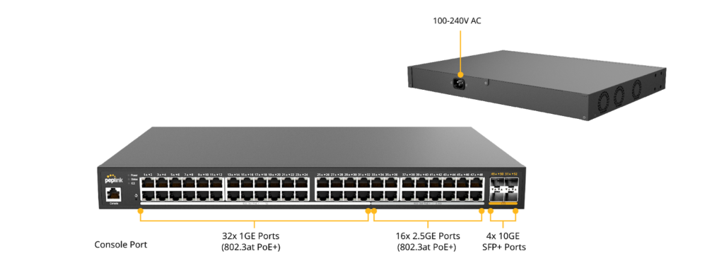
48 PoE 2.5G Switch#
LED Indicators:
| Status Indicators | ||
| Power | OFF | No power |
| Green (Solid light) | System boot on-going | |
| Green (Solid light) | System boot ready | |
| Status | OFF | System boot on-going / System off |
| Green (Solid light) | System boot ready | |
| IC2 | OFF | No link with IC2 |
| Green (Solid light) | IC2 connected | |
| Ethernet Ports | ||
| RJ45 Left LED (Activity) | OFF | Port is not connected |
| Amber ( Blinking) | Data is transferring | |
| Amber (Solid Light) | Port is connected | |
| RJ45 Right LED (PoE Switch) | Off | PoE disable |
| Green (Solid Light) | PoE Enable (even no cable is connected) | |
| RJ45 Right LED (PoE Switch) | Off | Other speed / No link |
| Green (Solid Light) | Highest speed | |
| SFP Ports | ||
| SFP LED (Activity) | Off | No link |
| Green (Blinking) | Activity | |
| Green (Solid light) | Link | |
| Reset Button | ||
| Hold reset button | 0 – 10 seconds | Status light (green) blinking slowly. |
| 10 -15 seconds | Status light (green) blinking fast | |
| Over 15 seconds | Status light off, release reset button and device start reboot. | |
Quick Start Guide#
Managed by InControl 2:
- Power on the switch and connect it to the internet.
Unbox your Peplink switch and power on the device. Once plugged in, the Power and Status lights will turn on.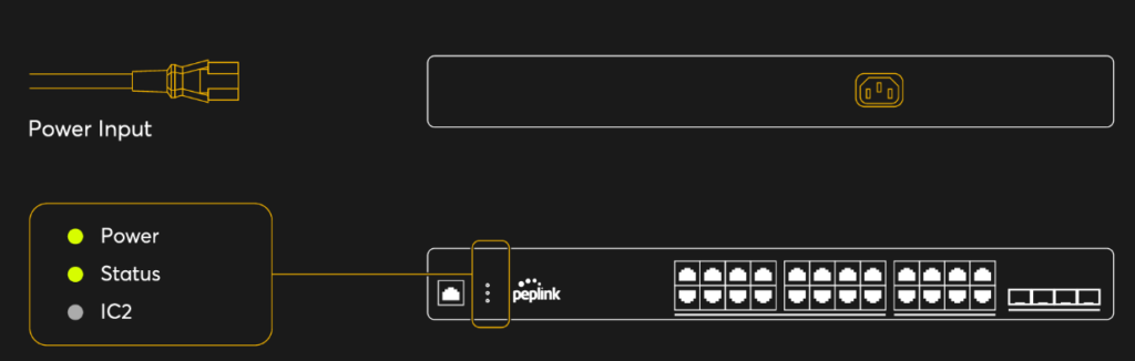
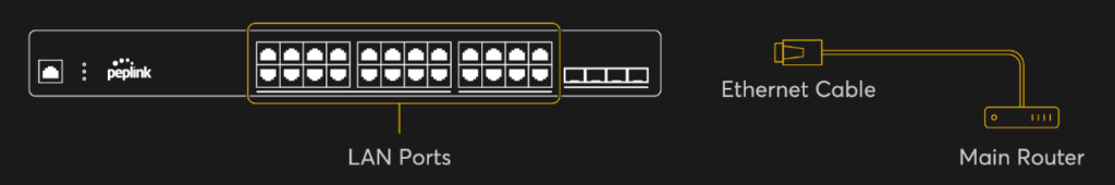
- Connect your switch to your local network by plugging a LAN cable into one of the available GE or SFP LAN ports.
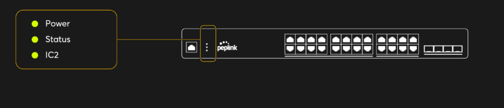
- The IC2 light will turn green when the device is ready to be configured on InControl 2.
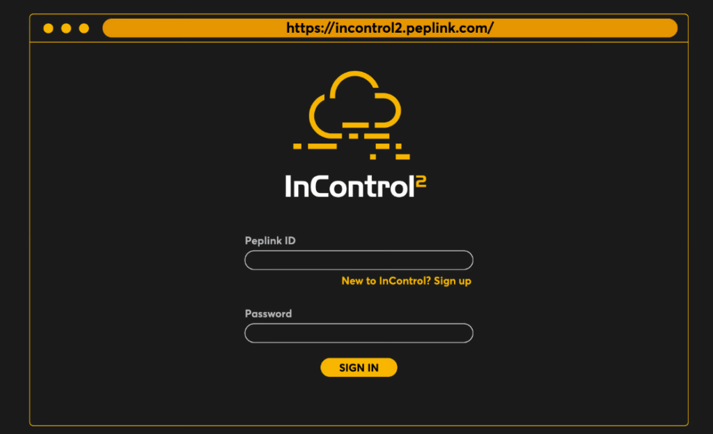
- Registering the switch on InControl 2. Navigate to InControl 2 and log in to your account. If you don’t have one yet, please create an account now.
- Navigate to the organization where you would like to assign the switch. For new accounts, please create a new organization and group.
- Under the Group Level, click Add Device.
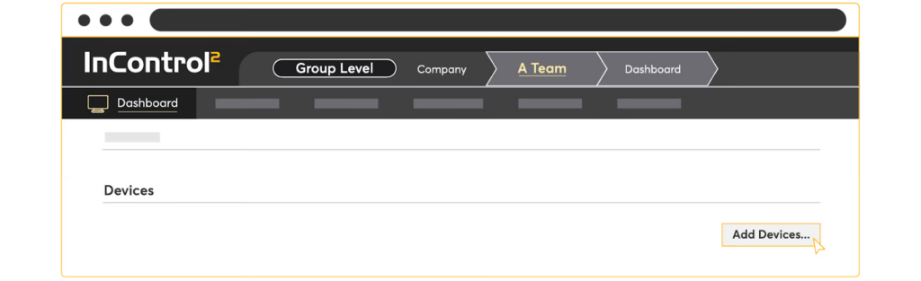
- Enter the Serial Number of your Peplink switch.

- Once the device is added, it should appear under your Group Level’s device list in InControl 2. A warning message icon will appear beside the Device Name, which is to advise the user to change the admin password.
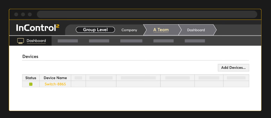

- To manage the device password, the user may enable the option “Device Web Admin and CLI Management” from InControl Group Level > Settings > Device System Management.
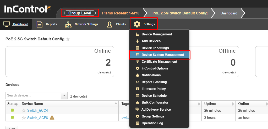
For more information about “Device Web Admin and CLI Management,” kindly refer to the “Securing InControl Access” section in the link below: https://forum.peplink.com/t/quick-and-easy-ways-to-secure-your-router/8062
You’re all set and ready to configure!
InControl 2 Configuration#
Through InControl, Peplink’s cloud-based device management and monitoring application, this section provides an overview of the InControl settings and information specific to the Peplink Switch.
The switch will appear online in InControl 2 if it successfully connects to the InControl servers (the marker on the map will change from red to green).
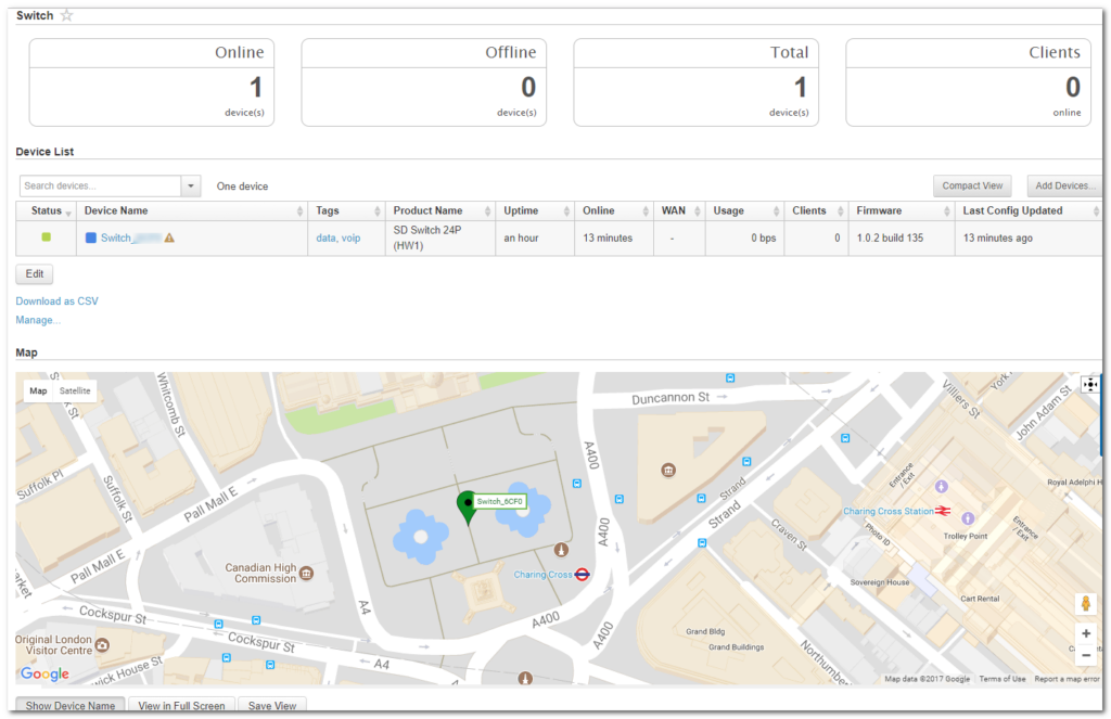
Tip: If a device appears offline in InControl, check the following knowledge base article for a solution:
InControl 2 Group Settings#
Organization > Group >Settings > Device Management
The InControl Group Settings device details show tags, product name, uptime, online time, clients, and firmware for each device.
This page also allows you to configure switch-specific options through the “Actions” drop-down list.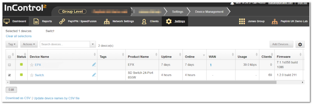
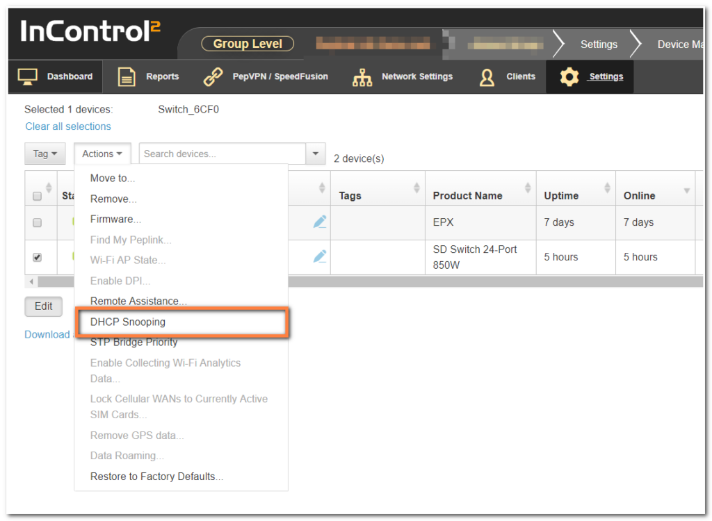
InControl DHCP Snooping#
Organization > Group >Settings > Device Management
Actions > DHCP Snooping
Prevent unauthorized DHCP servers from offering IP addresses to DHCP clients.
When this is enabled, DHCP server discovery messages will only be forwarded to switch ports that are configured with the “Allow DHCP Server” option in port details.
Default setting: Disabled
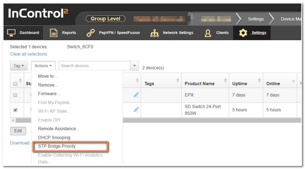
InControl STP Bridge Priority#
Spanning Tree Protocol (STP) uses the Spanning Tree Algorithm to avoid network loops in layer 2 devices. STP works when multiple switches are used with redundant links, preventing Broadcast Storms, Multiple Frame Copies, and Database Instability.
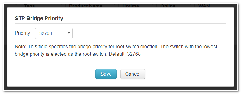
The priority field specifies the bridge priority for the root switch election.
The switch with the lowest bridge priority is elected as the root switch (Default value: 32768
Configuring VLANs#
Organization > Group > Network Settings > VLAN Networks
From the available InControl Group settings, the Network Settings > VLAN Networks section has several switch-specific settings and behaviors.
The switch can only be managed from InControl. VLAN One will be the default VLAN and cannot be changed or removed.
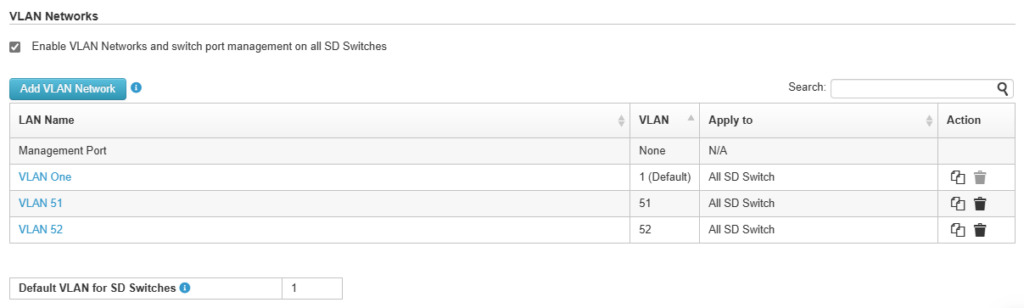
By default, this VLAN is applied to any device that is added to this group. Each VLAN can be applied to a selection of devices in the group using tags. Tags can be configured in the device details.
Detailed management of VLAN network settings:
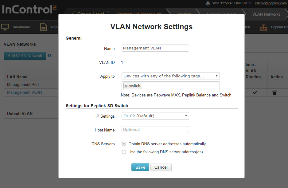
Define a new VLAN
To add a new VLAN click on the “Add VLAN Network” button in the Network settings > VLAN Networks section of InControl.
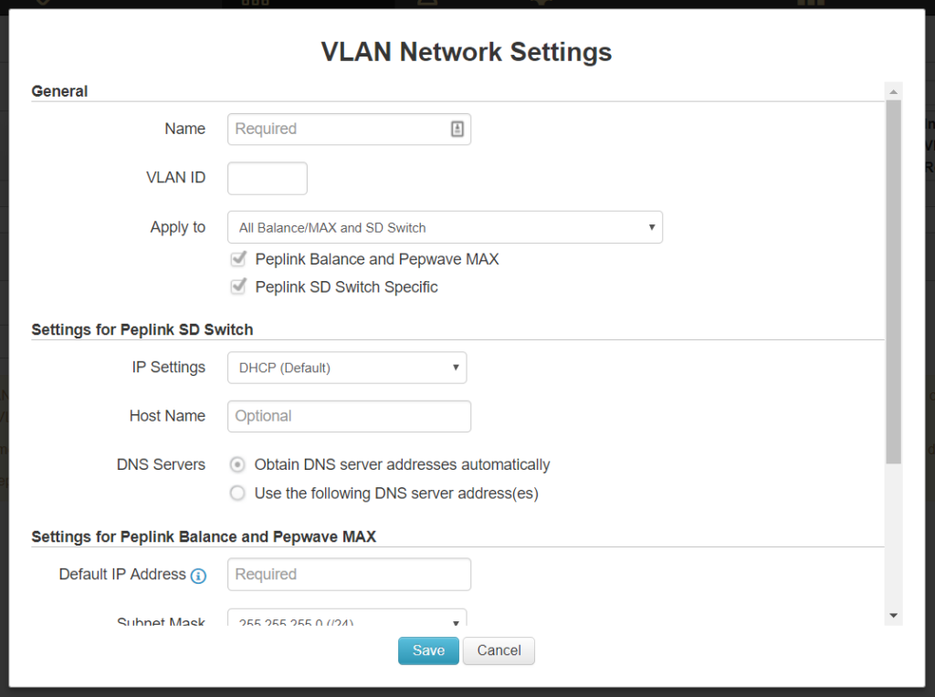
Enter the desired parameters and click “Save” to apply the settings.
Default VLAN Settings
The Default VLAN’s ID is 1 and cannot be changed. It only applies to the switch’s PVID-enabled trunk ports.
Untagged frames received by those ports will be classified as a VLAN identified by ID 1. All frames from the VLAN will be untagged on egress.
Note: The VLAN with ID 1 is always defined on the switches and cannot be changed or deleted.
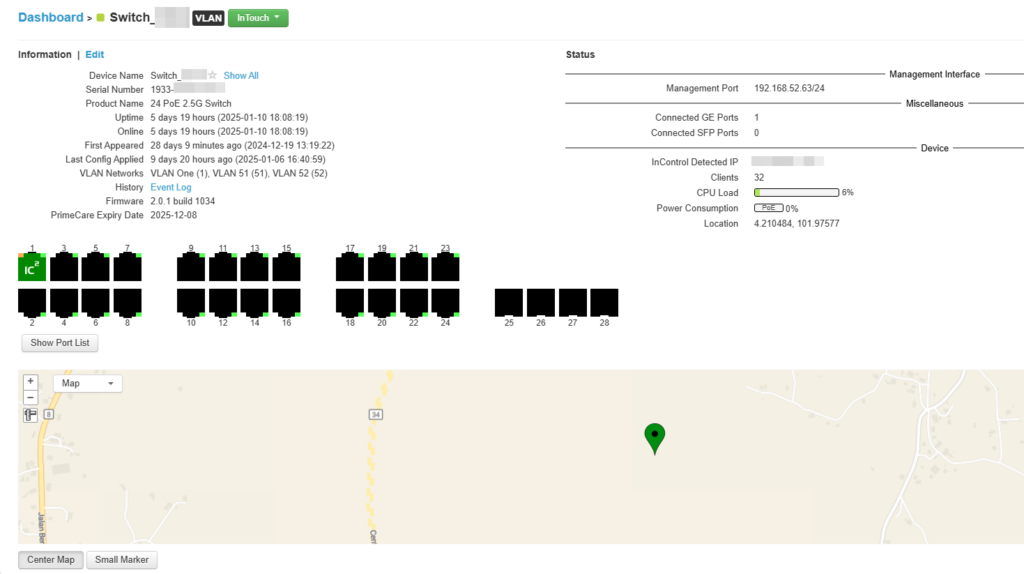
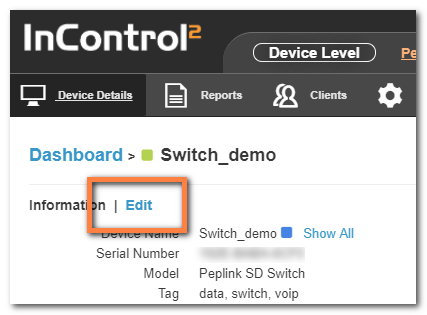
InControl Device Details#
The Device Details page shows the following detailed information about the Switch:
| Device Name | Firmware | Location |
| Serial Number | Warranty Expiry Date | Port List |
| Product Name | Management port IP | |
| Tags | Connected GE ports | |
| Uptime | Connected SFP/SFP+ ports | |
| Online | InControl Detected IP | |
| First Appeared | Clients | |
| History (event log) | Power Consumption |
Device name, tags, location, and notes can be changed through the “Edit” link:
Select the Save button on the bottom of this page to save the settings and return to the device details page.
Or Cancel to discard changes and return to the Device Settings page.
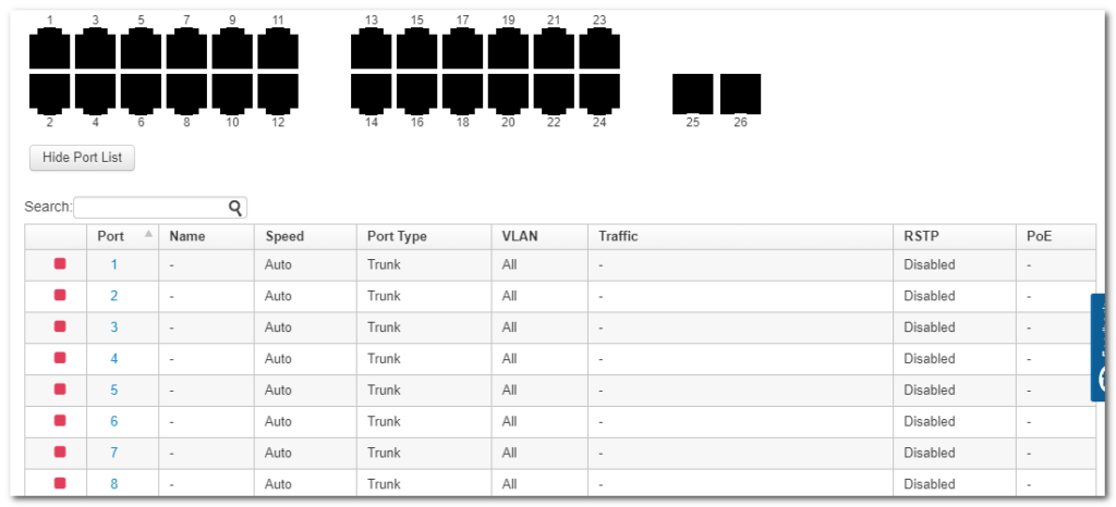
Port details
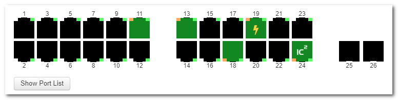
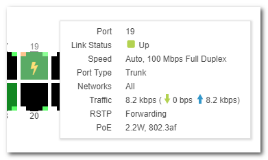
The Port List shows the available switch ports and their status. When hovering over an individual port, additional information is displayed for that particular port.
Ports 1 through 24 are RJ45 ports (Ethernet).
Ports 25 and 26 are SFP+ ports (fiber).
| Port Icons Glossary | |
 |
port down |
 |
port up – PoE not drawing power |
 |
port up -PoE drawing power |
 |
port up – link to InControl |
 |
Port up – PoE disabled |
Port Details and Configuration
Additional port details appear when clicking on an individual port from the device details page.
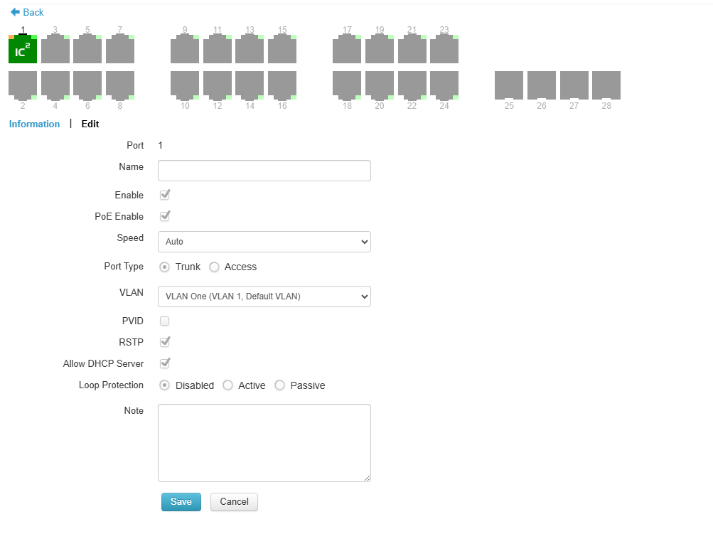
Single or multiple ports can be selected and edited.
| Configurable options (port 1 – 24) | |
| Enable / disable | Enable or disable the switch port |
| PoE enable / disable | Enable or disable PoE on the port |
| Speed^ | Select port speeds 1Gbps, 100Mbps, or 10 Mbps half or full Duplex or 1 Gbps full Duplex. |
| Port Type | Trunk or Access port |
| VLAN | CUSTOM (select 1 or more existing VLANs) |
| Accept Frame Type* | Frame Types the port accepts (VLAN tagged only, or All) |
| RSTP | Enable or disable RSTP (Rapid Spanning Tree Protocol) |
| Allow DHCP server* | Enable or disable IP assigned by DHCP |
| Loop Protection | Enable/disable loop protection. |
| Notes | Add additional notes |
| LACP | Link Aggregation |
^ Configuration options on certain ports are configurable port speeds to 2.5 Gbps. May refer to the datasheet or label below switch ports.
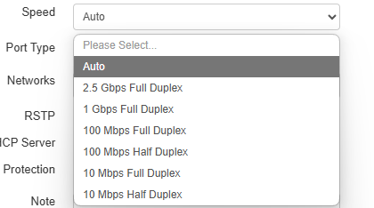
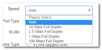
Configurable options on SFP+ ports are similar as above, but configurable port speeds are between 100 Mbps Full Duplex up to 10 Gbps Full Duplex.
* Frame Type setting determines whether the frame should be accepted or discarded.
This option is only configurable when the Port Type is set to “Trunk” and “VLAN Networks” is set to “All”.
Available options are:
- VLAN Tagged Only: Only accept frame types from VLANs( Tagged)
- All: accept both tagged and untagged frames; when any untagged frames or frames tagged as this VLAN enter into those trunk ports, they will be assigned to this VLAN. Any frames on this VLAN leaving from those trunk ports will be untagged
* The option “Allow DHCP server” is only visible in the InControl port options when DHCP snooping on the switch is enabled on the switch.
When DHCP snooping is enabled on the switch, this option enables DHCP snooping for the individual ports, setting the option as per the default setting on the device “trusted or untrusted”.
Port List
The port list can be shown or hidden by clicking on the show/hide button under the ports.
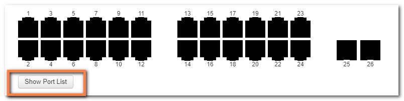
This will show (or hide) a table showing port details.
LACP – Link Aggregation
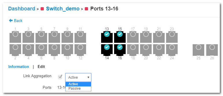
IEEE 802.3ad link aggregation enables you to group Ethernet interfaces to form a single link layer interface, also known as a link aggregation group (LAG).
The maximum number of interfaces per LAG is 24.
The advantages of link aggregation, in contrast with connections using an individual port, include:
- higher throughput speed compared to an individual port
- higher accessibility
To configure a Link Aggregation Group (LAG), click Edit after selecting multiple ports. Enable Link Aggregation by selecting the checkbox next to Link Aggregation. The LAG can be set to Active or Passive.
LACP needs to be set to active on 1 side at least for LACP to work.
Details of Connected Clients and Hourly, Daily, or Monthly Power Usage for each Port are shown in a graph on the same page.
InControl Reports#
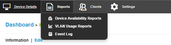
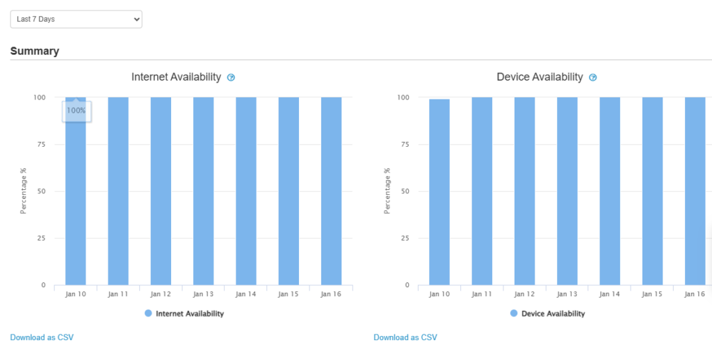
Device Availability Reports
Internet Availability – “Total amount of InControl online time of the device in the day” / “Total uptime of the device in the day”
Device Availability – “Total uptime of the device in the day” / “Total amount of time of the day”
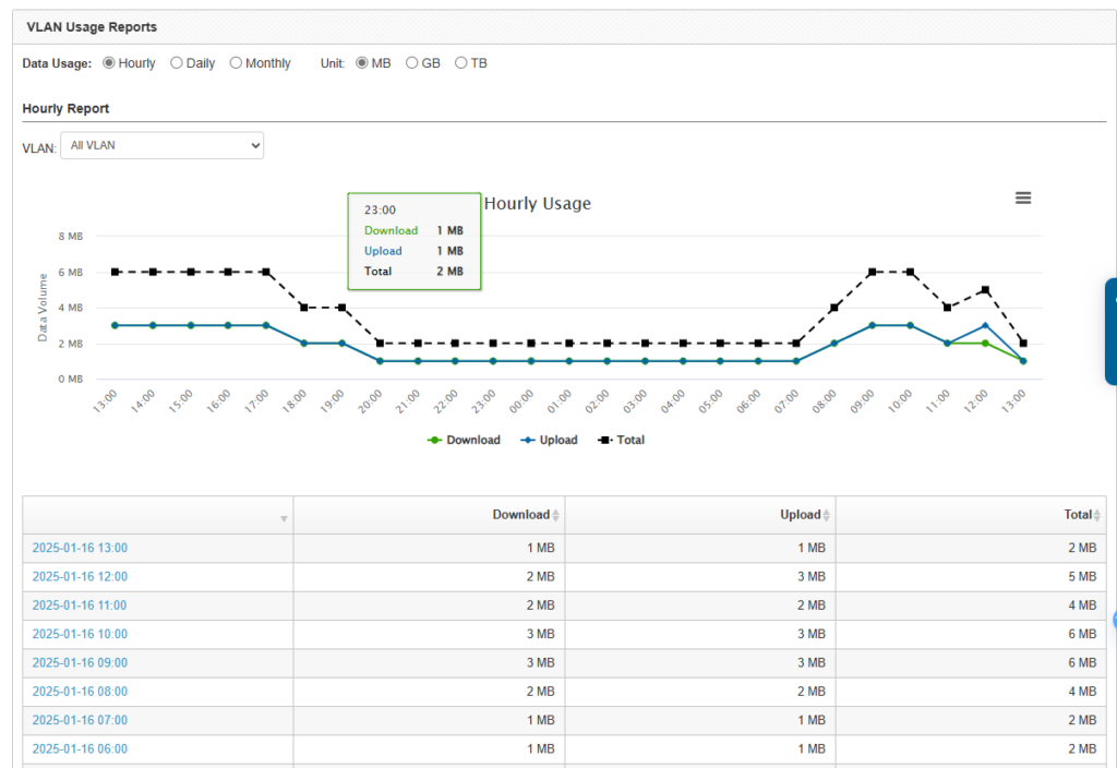
VLAN Usage Report
Event log
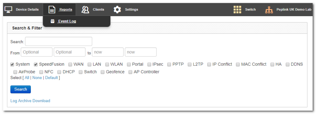
Search through the SD Switch event logs, and filter results by topic, time, client, and details.
Download the event log in .csv format.
InControl Clients#

View client details from client devices connected to the SD Switch.
InControl Settings#
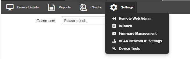
The InControl settings section gives access to the Remote Web Interface of the Switch. You can also control firmware management for all devices in this InControl group and Device Tools.
Settings > Remote Web Admin
Remote Web Admin opens the web admin interface of the SD Switch in a separate tab.
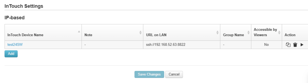
Settings > InTouch
InTouch is Peplink’s zero-touch remote network management solution, leveraging InControl 2 and a SpeedFusion Connect (formerly known as SpeedFusion Cloud) data plan. This service extends a network administrator’s ability to reach any device UI backed by a Peplink/Pepwave router. To configure InTouch, all you need is a valid InControl 2 subscription, a SpeedFusion Connect data plan, and a Peplink/Pepwave router (which requires the latest 8.2.0 firmware).
To watch a demonstration and read the FAQ, visit https://www.peplink.com/enterprise-solutions/intouch/
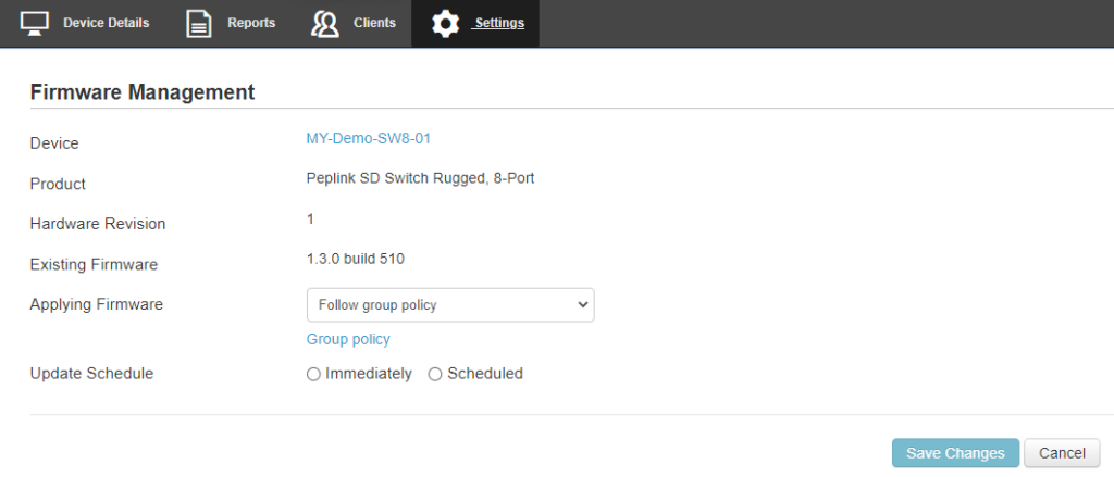
Settings > Firmware Management
Settings > Device Tools
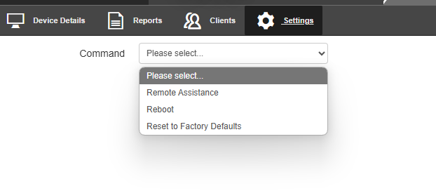
| Command | |
| Remote Assistance | Turn On/Off of Remote Assistance |
| Reboot | Apply and reboot the device. |
| Reset to Factory Defaults | Apply and factory default the device. |
Web Admin Configuration#
Getting Started#
To access the switch’s web interface without DHCP uplink connection :
- Power On the switch without an uplink connection.
- Connect your laptop/PC to any of the switch ports.
- Make sure your laptop/PC ethernet connection is configured using 192.168.1.0/24 network.
- Open a web browser and enter the default Management IP address http://192.168.1.254 or https://192.168.1.254 to access the switch’s web admin interface.
Caution: The management IP address will no longer be 192.168.1.254 if the uplink connection is connected and the switch external access is obtained a DHCP IP from the network.
To access the switch’s web interface with DHCP uplink connection :
- Connect the switch to your network and power it on.
- Open a web browser on a device within the same network.
- Check the client list on your main router’s web admin to determine the switch’s IP address in the network. If a Peplink router is used, this is the interface where you can check the client list.
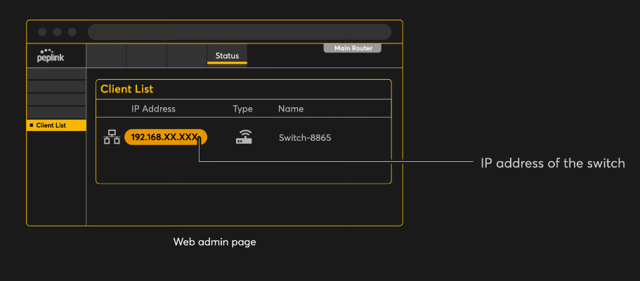
- Enter the IP address of the switch’s web admin interface (http/https). You can obtain the IP address from the main router client list.
Log in with your credentials to access the interface.

Login with the default credentials:
Username: admin
Password: admin
This is the default admin user login of the Peplink Switch. The admin and read-only user password can be changed at System>Admin Security on InControl 2.
Uplink Configuration Section#
This section explains how to configure the Uplink Settings for the device.
External Access Settings
- Mode:
- Auto: The device scans through all VLAN IDs (1-4094) and attempts to establish a connection using DHCP automatically. This mode is recommended for dynamic environments where VLAN and IP assignments are managed automatically.
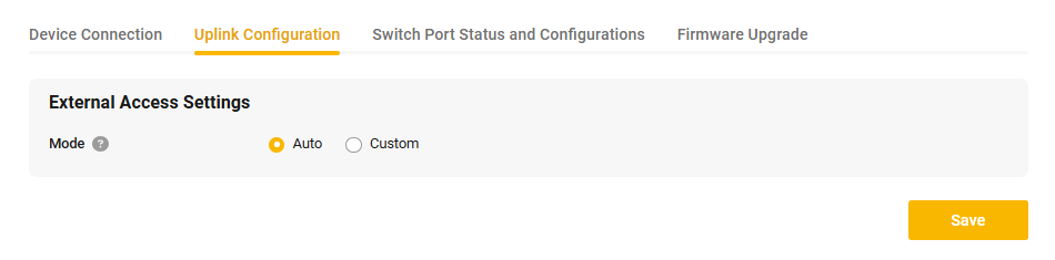
- Custom: Allows you to manually define the VLAN ID and specify the connection method (e.g., DHCP or Static IP). This mode is suitable for networks requiring specific configurations for connectivity.
- Auto: The device scans through all VLAN IDs (1-4094) and attempts to establish a connection using DHCP automatically. This mode is recommended for dynamic environments where VLAN and IP assignments are managed automatically.
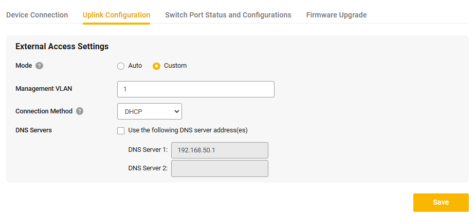
Custom Mode Configuration
When Custom Mode is selected under the External Access Settings, you can manually configure the uplink settings according to specific network requirements. Below are the configurable options:
- Management VLAN
- Enter the VLAN ID that will be used for the device’s management traffic.
- This allows the device to operate within a specific VLAN in your network setup.
- Connection Method
- Select the method the device will use to obtain an IP address. The options include:
- DHCP: Automatically acquire an IP address from a DHCP server in the specified VLAN.
- Static IP: Manually set the IP address, subnet mask, and gateway. This is used when the network requires fixed addressing.
- Select the method the device will use to obtain an IP address. The options include:
- DNS Servers
- If custom DNS settings are required, check the box to enable the Use the following DNS server address(es) option.
- Enter the preferred and alternate DNS server addresses:
- DNS Server 1: Specify the primary DNS server for name resolution.
- DNS Server 2: Optionally, specify a secondary DNS server as a fallback.
Caution: Before changing the Management VLAN, ensure that the switch port trunk/access port for the VLAN is configured first to avoid losing access to the switch via local access or IC2 access. A factory reset is required if the wrong Management VLAN is configured.
Switch Port Status and Configurations#
This section provides an overview and customization options for the switch ports. It allows you to monitor the status and configure each port to meet specific network requirements.
Port Settings Overview
The interface displays a visual representation of the ports and their statuses, along with a detailed table for configuration.
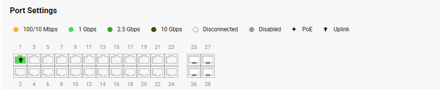
Port Indicators
- 100/10 Mbps (Yellow): Indicates the port is connected and operating at 10 or 100 Mbps.
- 1 Gbps (Light Green): Indicates the port is connected and operating at 1 Gbps.
- 2.5 Gbps (Green): Indicates the port is connected and operating at 2.5 Gbps.
- 10 Gbps (Dark Green): Indicates the port is connected and operating at 10 Gbps.
- Disconnected (Gray): Indicates the port is not connected to a device.
- Disabled (Dark Gray): Indicates the port has been manually disabled.
- PoE (Power over Ethernet): Displays whether the port supports PoE, providing power to connected devices like IP cameras or access points.
- Uplink: Highlights if the port is used as an uplink to connect to other network infrastructure.
Port Configuration Table
The table provides the following configuration options for each port:
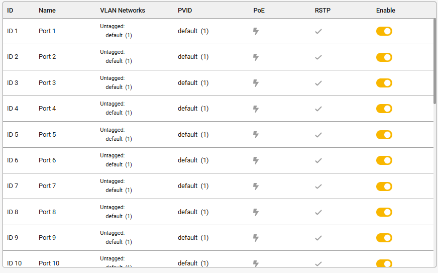
- ID: Displays the unique identifier for the port.
- Name: The user-defined name of the port.
- VLAN Networks: Lists the VLAN configurations associated with the port (tagged or untagged).
- PVID (Port VLAN ID): Displays the VLAN ID associated with untagged traffic on the port.
- PoE: Indicates if PoE is enabled on the port. An icon signifies PoE capability.
- RSTP (Rapid Spanning Tree Protocol): Shows whether RSTP is enabled to prevent loops in the network.
- Enable: Toggles the port on or off.
Appendix List#
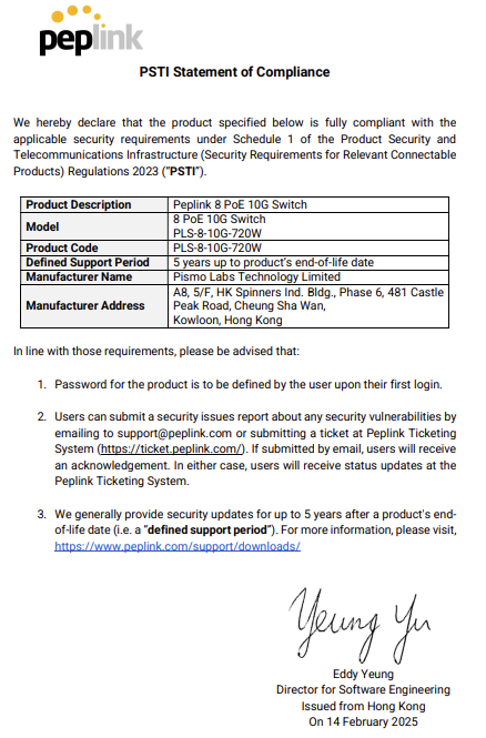
Appendix B. UK PSTI Statement of Compliance#
For 8 PoE 10G Switch
For 24 PoE 2.5G Switch
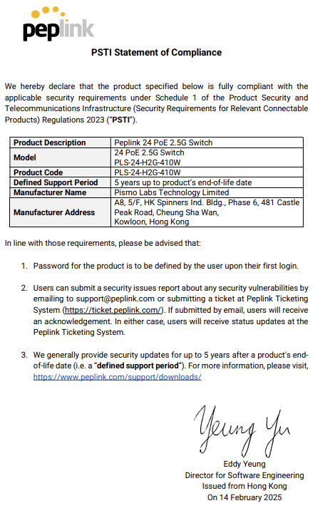
For 24 PoE 2.5G Switch

For 24 PoE 2.5G Switch Rugged

For 48 PoE 2.5G Switch
