Peplink AP One Firmware 3.9.4 User Manual#
Peplink AP One / Peplink AP Pro Series:
AP One AX / AP One AX Lite / AP One Rugged / AP Pro AX / AP One Mini / AP One AC Mini
Peplink AP One Firmware 3.9.4
June 2025
Introduction and Scope#
Our AP Series of enterprise-grade 802.11ax/ac/a/b/g/n Wi-Fi access points is engineered to provide fast, dependable, and flexible operation in a variety of environments, all controlled by an easy-to-use centralized management system.
From the small but powerful AP One AC Mini to the top-of-the-line AP Pro Duo our AP Series offers wireless networking solutions to suit any business need, and every access point is loaded with essential features such as multiple SSIDs, VLAN, Mesh, WDS, and Guest Protect.
A single access point provides as many as 32 virtual access points (16 on single-radio models), each with its own security policy (WPA, WPA2, etc.) and authentication mechanism (802.1x, open, captive portal, etc.), allowing faster, easier, and more cost-effective network builds.
Each member of the AP Series family also features a high-powered Wi-Fi transmitter that greatly enhances coverage and performance while reducing equipment costs and maintenance.
Ch1. Product Features and Benefits#
Key features and benefits of AP Series access points:
- High-powered Wi-Fi transmitter that enhances coverage and lowers cost of ownership.
- Independent security policies and encryption mechanisms for each virtual access point allow fast, flexible, cost-effective network builds.
- Centralized management via InControl reduces maintenance expense and time.
- Mesh support allows for wireless expansion and enhancement of Wi-Fi coverage.
- WDS support allows secure and fast network expansion.
- Guest Protect support guards sensitive business data and subnetworks.
- WMM (Wi-Fi Multimedia) and QoS (Quality of Service) support keeps video and other bandwidth-intensive data flowing fast and lag-free.
- Supports Wi-Fi Air Monitoring for remote troubleshooting, and proactively monitoring Wi-Fi and WAN performance.
Ch2. Package Contents#
AP One AX (APO-AX)
1 x AP One AX
1 x Ceiling Mount
1 x Screw Kit
AP One AX Lite (APO-AX-LITE)
1 x AP One AX Lite
1 x Ceiling Mount
1 x Screw Kit
AP One Rugged (APO-AC-RUG)
1 x AP One Rugged
1 x 12V2A Power Supply
2 x Dual Band Wi-Fi Antennas
AP Pro AX (APP-AX-IP67)
1x AP Pro AX
1x Water Proof M25 Ethernet cable gland
1x Water Proof DC power plug
1x Mounting kit 1x M6 screw set
1x Wall screw with anchor set
AP One Mini (APO-AC-MINI)
1 x AP One Mini
1 x 12V2A Power supply
1 x Mounting Bracket
AP One AC Mini (APO-AC-MINI)
1 x AP One AC Mini
1 x 12V2A Power supply
1 x Mounting Bracket
Ch3. Hardware Overview#
AP One AX#
Front View Top
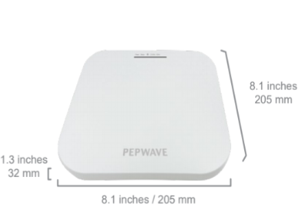
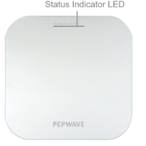
Side Bottom
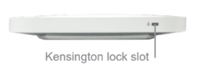
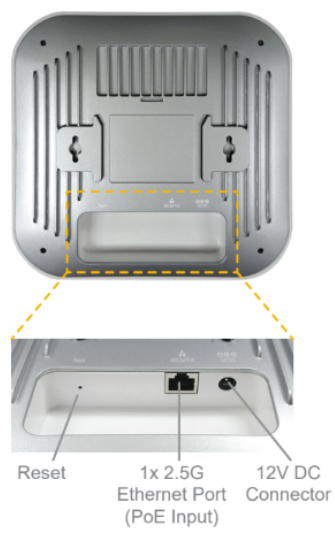
| LED Indicators | ||
| Power
|
Blue LED | OFF – Power is Off
ON – Power is On |
| Status
|
Blue LED | OFF – Access point is initializing
ON – Access point is ready |
| Ethernet Port
|
Blue LED | OFF – No data is being transferred or no device is connected to the Ethernet port
BLINKING – Ethernet port is sending/receiving data ON – A powered-on device is connected to Ethernet port |
| Port Type | Auto MDI/MDI-X ports | |
| Wi-Fi
|
Blue LED | OFF – 2.4/5GHz Wi-Fi radio is off
ON – 2.4/5GHz Wi-Fi radio is on / no Wi-Fi mesh uplink BLINKING – Indicates the state of the 2.4/5GHz Wi-Fi mesh uplink |
AP One AX Lite#
Front View
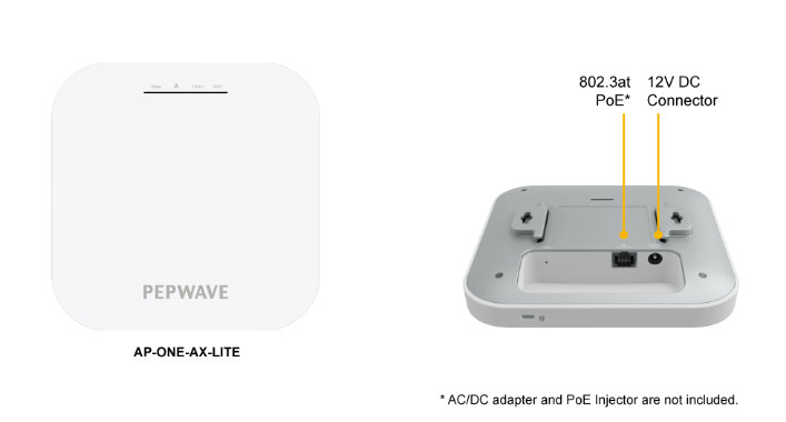
| LED Indicators | ||
| Status
|
Blue LED | OFF – Access point is initializing
ON – Access point is ready |
| Ethernet Port
|
Blue LED | OFF – No data is being transferred or no device is connected to the Ethernet port
BLINKING – Ethernet port is sending/receiving data ON – A powered-on device is connected to the Ethernet port |
| Port Type | Auto MDI/MDI-X ports | |
| Wi-Fi
|
Blue LED | OFF – 2.4/5GHz Wi-Fi radio is off
ON – 2.4/5GHz Wi-Fi radio is on / no Wi-Fi mesh uplink BLINKING – Indicates the state of the 2.4/5GHz Wi-Fi mesh uplink state |
AP One Rugged#
Front View
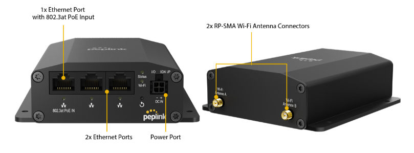
| LED Indicators | ||
| Status | RED – Access point is initializing
GREEN – Access point is ready |
|
| Wi-Fi | OFF – Wi-Fi AP is off
GREEN – Wi-Fi AP is on |
|
| Ethernet Port | ON – Port is connected without traffic LAN
BLINKING – Ethernet port sending/receiving data OFF – No data is being transferred or No device connected to Ethernet port |
|
AP Pro AX#
Front View
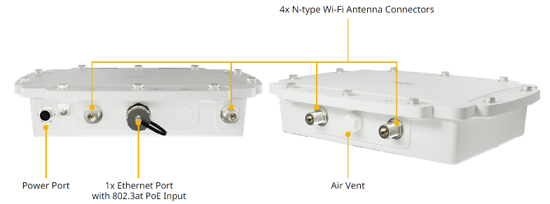
| LED Indicators | ||
| Status | OFF – Access point is initializing
ON – Access point is ready |
|
AP Pro AX (HW2)#
Front View
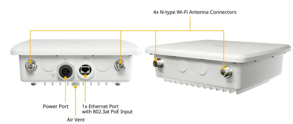
| LED Indicators | ||
| Status | OFF – Access point is initializing
ON – Access point is ready |
|
AP One Mini#

| LED Indicators | ||
| Status | RED – Access point is initializing
GREEN – Access point is ready |
|
| Wi-Fi | OFF – 2.4/5GHz Wi-Fi radio off
BLINKING – AP sending/receiving data GREEN – 2.4/5GHz Wi-Fi radio on Note that this model includes a 2.4GHz Wi-Fi radio and a 5GHz Wi-Fi radio that can operate simultaneously to increase speed and reduce interference. |
|
AP One AC Mini#

| LED Indicators | ||
| Status | RED – Access point is initializing
GREEN – Access point is ready |
|
| Wi-Fi | OFF – 2.4/5GHz Wi-Fi radio off
BLINKING – AP sending/receiving data GREEN – 2.4/5GHz Wi-Fi radio on Note that this model includes a 2.4GHz Wi-Fi radio and a 5GHz Wi-Fi radio that can operate simultaneously to increase speed and reduce interference. |
|
Ch4. Installation#
Your access point acts as a bridge between wireless and wired Ethernet interfaces.
A typical setup follows:
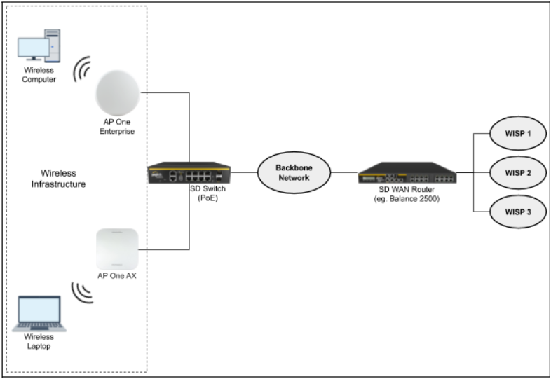
Installation Procedures
- Connect the Ethernet port on the unit to the backbone network using an Ethernet cable. The port should auto sense whether the cable is straight-through or crossover.
- There are two methods to power on the device as below:
- For those Pepwave AP devices having built-in PoE ports only, using an Ethernet cable to connect to the Power over Ethernet (PoE) switch or PoE injector.
- For those Pepwave AP devices that have a DC power source, plug the AC adapter to the DC connector of the unit.
- Wait for the status LED to turn green.
- Connect a PC to the backbone network. Configure the IP address of the PC to be any IP address between 192.168.0.4 and 192.168.0.254, with a subnet mask of 255.255.255.0.
- Using your favourite browser, connect to https://192.168.0.3.
- Enter the default admin login ID and password, admin and public respectively.
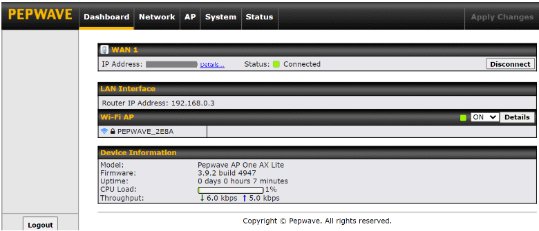
- After logging in, the Dashboard appears. Click the System tab to begin setting up your access point.
Ch5. Dashboard#
The Dashboard section contains a number of displays to keep you up-to-date on your access point’s status and operation. Remote assistance can also be turned off here, if it has been enabled.
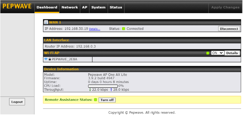

This section contains WAN status and general device information.
| WAN | |
| IP Address | When your access point is connected to a WAN, this field displays the WAN IP address. For more information, click the Details link which shows connection type details |
| Status | This field displays the current WAN connection status. |

| Device Information | |
| Model | This field displays your access point’s model number. |
| Firmware | The firmware version currently running on your access point appears here. |
| Uptime | This field displays your access point’s uptime since the last reboot or shutdown. |
| CPU Load | This field shows current loading (0%-100%) on your access point. |
| Throughput | This field displays your access point’s transfer rate in kbps. |
Ch6. Network#
The settings on the Network tab control WAN, LAN, and Port Settings. It also allows you to set up Captive Portal profiles and Misc Settings.
Additionally, some settings on the Network tab are able to control PepVPN, Inbound Access, NAT Mapping, and QoS when your access point is operating in Router Mode.
WAN#
WAN connection details need to be configured in order to connect the router to the Internet.

To configure a WAN connection, go to Network > WAN from the menu and select the desired WAN connection by clicking on its name.
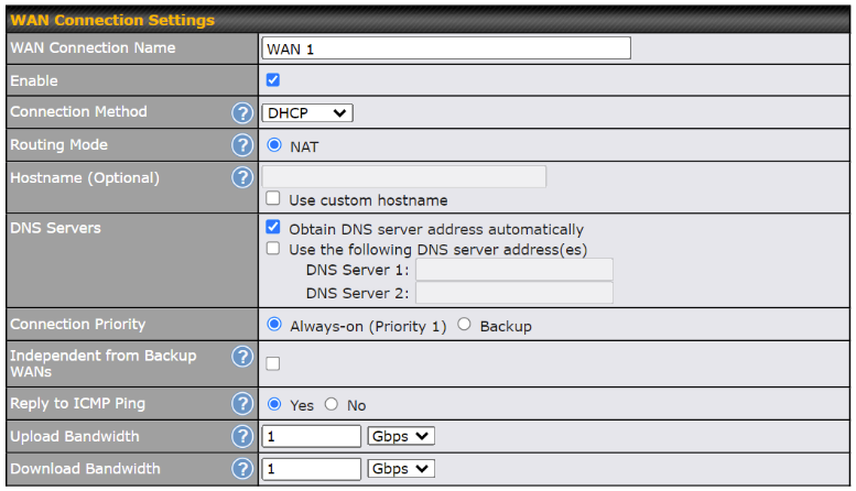
| WAN Connection Settings | |
| WAN Connection Name | Enter a name to represent this WAN connection. |
| Enable | This setting enables the WAN connection. If schedules have been defined, you will be able to select a schedule to apply to the connection. |
| Connection Method | There are three possible connection methods for Ethernet WAN:
The connection method and details are determined by, and can be obtained from the ISP. |
| Hostname | Provide a hostname for this WAN port if requested by the ISP. |
| DNS Server | Enter the DNS server address that your access point will use to resolve host names. |
| Connection Priority | This option allows you to configure the WAN connection, whether for normal daily usage or as a backup connection only.
If Always-on is selected, the WAN connection will be kept on continuously, regardless of the priority of other WAN connections. If Backup is selected, the WAN connection will depend on other WAN connections. It will not be used when one or more higher priority dependent WAN connections are connected. |
| Independent from Backup WANs | If this is checked, the connection will be working independently from other backup WAN connections. WAN connections whose Connection Priority are set to Backup will ignore the status of this WAN connection, and will be used when none of the other higher priority connections are available. |
| Reply to ICMP Ping | If the checkbox is unticked, this option is disabled and the system will not reply to any ICMP ping echo requests to the WAN IP addresses of this WAN connection.
Default: ticked (Yes) |
| Upload Bandwidth | This field refers to the maximum upload speed.
This value is referenced when default weight is chosen for outbound traffic and traffic prioritization. A correct value can result in effective traffic prioritization and efficient use of upstream bandwidth. |
| Download Bandwidth | This field refers to the maximum download speed. Default weight control for outbound traffic will be adjusted according to this value. |

| Physical Interface Settings | |
| Port Speed | This is the port speed of the WAN connection. It should be set to the same speed as the connected device in case of any port negotiation problems.
When a static speed is set, you may choose whether to advertise its speed to the peer device or not. In this setting, Advertise Speed is selected by default. You can choose not to advertise the port speed if the port has difficulty in negotiating with the peer device. The default setting for Port Speed is: Auto. |
| MTU | This field is for specifying the Maximum Transmission Unit value of the WAN connection. An excessive MTU value can cause file downloads to stall shortly after connecting. You may consult your ISP for the connection’s MTU value.
The default value is 1440. |
| MSS | This setting should be configured based on the maximum payload size that the local system can handle. The MSS (maximum segment size) is computed from the MTU minus 40 bytes for TCP over IPv4. If the MTU is set to Auto, the MSS will also be set automatically.
By default, MSS is set to Auto. |
| MAC Address Clone | Some service providers (e.g. cable providers) identify the client’s MAC address and require the client to always use the same MAC address to connect to the network. In such cases, change the WAN interface’s MAC address to the original client PC’s MAC address via this field. The default MAC address is a unique value assigned at the factory. In most cases, the default value is sufficient. Clicking Default restores the MAC address to the default value. |
| VLAN | Click the square if you wish to enable VLAN functionality for the WAN connection and enable multiple broadcast domains. Once you enable VLAN, you will be able to enter a name for your network. |
Health Check Settings
To ensure traffic is routed only to healthy WAN connections, the Pepwave AP can periodically check the health of each WAN connection. The health check settings for each WAN connection can be independently configured via Network > WAN > *Connection Name* > Health Check Settings.
| Health Check Settings | |
| Health Check Method | This setting specifies the health check method for the WAN connection. This value can be configured as Disabled, PING, DNS Lookup, or HTTP. The default method is DNS Lookup.
When Disabled is chosen in the method field, the WAN connection will always be considered as up. The connection will NOT be treated as down in the event of IP routing errors.
ICMP ping packets will be issued to test the connectivity with a configurable target IP address or hostname. A WAN connection is considered as up if ping responses are received from either one or both of the ping hosts. PING Host: This setting specifies IP addresses or hostnames with which connectivity is to be tested via ICMP ping. If the Use first two DNS servers as Ping Hosts is checked, the target ping host will be the first DNS server for the corresponding WAN connection. Reliable ping hosts with a high uptime should be considered. By default, the first two DNS servers of the WAN connection are used as the ping hosts.
DNS lookups will be issued to test connectivity with target DNS servers. The connection will be treated as up if DNS responses are received from one or both of the servers, regardless of whether the result was positive or negative. DNS Servers: This field allows you to specify two DNS hosts’ IP addresses with which connectivity is to be tested via DNS Lookup. If the Use first two DNS servers as Health Check DNS Servers is checked, the first two DNS servers will be the DNS lookup targets for checking a connection’s health. If the box is not checked, Host 1 must be filled, while a value for Host 2 is optional. If the Include public DNS servers is checked and no response is received from all specified DNS servers, DNS lookups will also be issued to some public DNS servers. A WAN connection will be treated as down only if there is also no response received from the public DNS servers. Connections will be considered as up if DNS responses are received from any one of the health check DNS servers, regardless of a positive or negative result. By default, the first two DNS servers of the WAN connection are used as the health check DNS servers.
HTTP connections will be issued to test connectivity with configurable URLs and strings to match. URL 1: The URL will be retrieved when performing an HTTP health check. When Matching String is left blank, a health check will pass if the HTTP return code is between 200 and 299 (Note: HTTP redirect codes 301 or 302 are treated as failures). When Matching String is filled, a health check will pass if the HTTP return code is between 200 and 299 and if the HTTP response content contains the string. URL 2: If URL 2 is also provided, a health check will pass if either one of the tests passed. |
| Timeout | If a health check test cannot be completed within the specified amount of time, the test will be treated as failed. |
| Health Check Interval | This is the time interval between each health check test. |
| Health Check Retries | This is the number of consecutive health check failures before treating a connection as down. |
| Recovery Retries | This is the number of responses required after a health check failure before treating a connection as up again. |
Additional IP Address Settings

| Additional IP Address Settings | |
| Additional IP Address | The IP Address list represents the list of fixed Internet IP addresses assigned by the ISP in the event that more than one Internet IP address is assigned to this WAN connection. |
Dynamic DNS Settings
Pepwave access points are capable of registering the domain name relationships to dynamic DNS service providers. Through registration with dynamic DNS service provider(s), the default public Internet IP address of each WAN connection can be associated with a host name. With dynamic DNS service enabled for a WAN connection, you can connect to your WAN’s IP address from external sources, even if its IP address is dynamic. You must register for an account from the listed dynamic DNS service providers before enabling this option.
If the WAN connection’s IP address is a reserved private IP address (i.e. behind a NAT router), the public IP of each WAN will be automatically reported to the DNS service provider.
Either upon a change in IP addresses or every 23 days without link reconnection, the Pepwave router will connect to the dynamic DNS service provider to perform an IP address update within the provider’s records.

| Dynamic DNS Settings | |
| Service Provider | This setting specifies the dynamic DNS service provider to be used for the WAN based on supported dynamic DNS service providers:
When Others… is selected, it supports custom Dynamic DNS servers by entering its URL. Works with any service compatible with DynDNS API. Select Disabled to disable this feature. |
| User ID / Username / Email | This setting specifies the registered user name for the dynamic DNS service. |
| Password | This setting specifies the password for the dynamic DNS service. |
| Hosts | This setting specifies a list of hostnames or domains to be associated with the public Internet IP address of the WAN connection. |
| Update All Hosts | Check this box to automatically update all hosts. |
DNS over HTTPS (DoH)
*Please note that the following settings are available only for AP One Rugged (HW2).
You can enable the DoH support in this section.

When this option is enabled, the DNS proxy server will use HTTPS connection to forward DNS requests to the DoH resolver, it will not fallback to traditional UDP DNS.
To configure custom DNS over HTTPS resolver, select Custom URL:, enter resolver URL and IP address.

| DNS over HTTPS | |
| Enable | When this option is enabled, the DNS proxy server will use HTTPS connections to forward DNS requests to the DoH resolver; it will not fallback to traditional UDP DNS options. |
| Server | The options to configure DoH with a predefined server are:
|
WAN Quality Monitoring
This settings advice how WAN Quality information is being gathered.

By default, WAN Quality will always be observed and gathered automatically. With customized choice of WAN connections, the device will always observe WAN Quality of those selected WAN connections. Other WAN connections may stop observing WAN Quality information if it is not necessary for the underlying features.
LAN#
Network Settings#
LAN interface settings are located at Network > LAN > Network Settings. Navigating to that page will show the following dashboard:

Clicking on any of the existing LAN interfaces (or creating a new VLAN) will show the following:
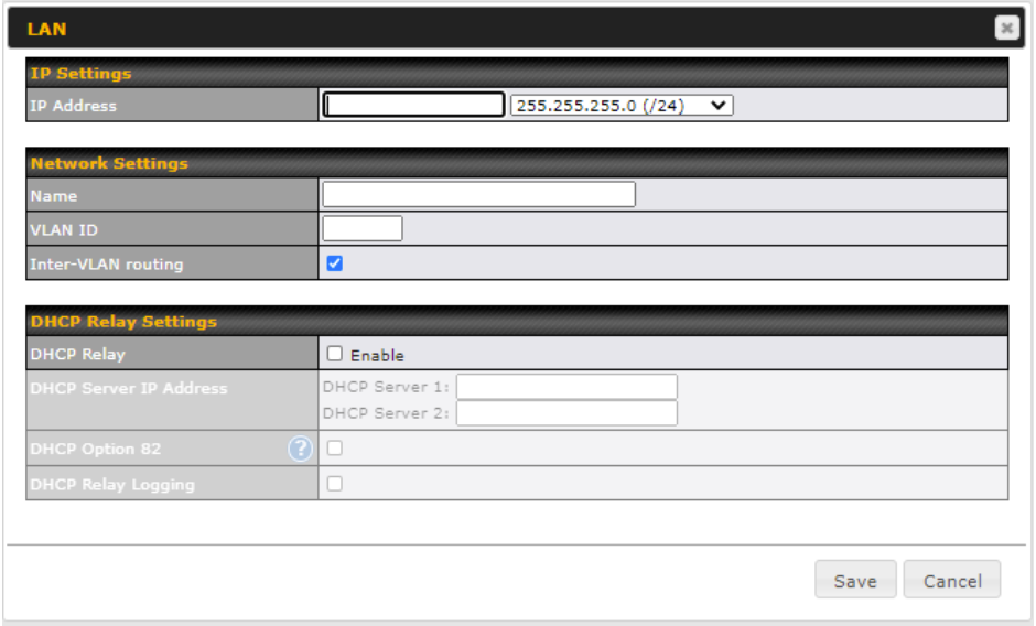
| IP Settings | |
| IP Address | Enter the LAN IP address and subnet mask of the Pepwave access point on the LAN. |
| NetworkSettings | |
| Name | Enter a name for the LAN. |
| VLAN ID | Enter a number for your VLAN. |
| Inter-VLAN routing | Check this box to enable routing between virtual LANs. |
| DHCP Relay Settings | |
| DHCP Relay | Check the Enable box to enable the DHCP Relay server. |
| DHCP Server IP Address | Enter the IP addresses of one or two DHCP servers in the provided fields. The DHCP servers entered here will receive relayed DHCP requests from the LAN. For active-passive DHCP server configurations, enter active and passive DHCP server relay IP addresses in DHCP Server 1 and DHCP Server 2. |
| DHCP Option 82 | This feature includes device information as a relay agent for the attached client when forwarding DHCP requests from a DHCP client to a DHCP server. Device MAC address and network name are embedded to circuit ID and Remote ID in option 82. |
| DHCP Relay Logging | Enable logging of DHCP events in the eventlog by selecting the checkbox. |
*Please note that the following settings will be available only when your access point is operating in Router Mode.

| DHCP Server Settings | |
| DHCP Server | When this setting is enabled, the DHCP server automatically assigns an IP address to each computer that is connected via LAN and configured to obtain an IP address via DHCP. The Pepwave router’s DHCP server can prevent IP address collision on the LAN. |
| DHCP Server Logging | Enable logging of DHCP events in the eventlog by selecting the checkbox. |
| IP Range | These settings allocate a range of IP addresses that will be assigned to LAN computers by the Pepwave router’s DHCP server. |
| Lease Time | This setting specifies the length of time throughout which an IP address of a DHCP client remains valid. Upon expiration of the lease time, the assigned IP address will no longer be valid and renewal of the IP address assignment will be required. |
| DNS Servers | This option allows you to input the DNS server addresses to be offered to DHCP clients. If Assign DNS server automatically is selected, the Pepwave router’s built-in DNS server address (i.e. LAN IP address) will be offered. |
| BOOTP | Check this box to enable BOOTP on older networks that still require it. |
| Extended DHCP Option | In addition to standard DHCP options (e.g., DNS server address, gateway address, subnet mask), you can specify the value of additional extended DHCP options, as defined in RFC 2132. With these extended options enabled, you can pass additional configuration information to LAN hosts.
To define an extended DHCP option, click the Add button, choose the option to define, and then enter its value. For values that are in IP address list format, you can enter one IP address per line in the provided text area input control. Each option can be defined once only. |
| DHCP Reservation | This setting reserves the assignment of fixed IP addresses for a list of computers on the LAN. The computers to be assigned fixed IP addresses on the LAN are identified by their MAC addresses. The fixed IP address assignment is displayed as a cross-reference list between the computers’ names, MAC addresses, and fixed IP addresses.
Name (an optional field) allows you to specify a name to represent the device. MAC addresses should be in the format of 00:AA:BB:CC:DD:EE. Click on |
Port Settings#
To configure port settings, navigate to Network > LAN > Port Settings.

On this screen, you can configure the name of the LAN port and enable or disable a specific port.
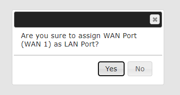
If the operating mode is set to Router Mode, you can change the device’s WAN port to a LAN port by going to Network > Port Settings, clicking on the WAN icon, and pressing Yes to convert it to a LAN port.

PepVPN#
PepVPN securely connects one or more remote sites to the site running your access point.
*Please note that the following settings will be available only when your access point is operating in Router Mode.
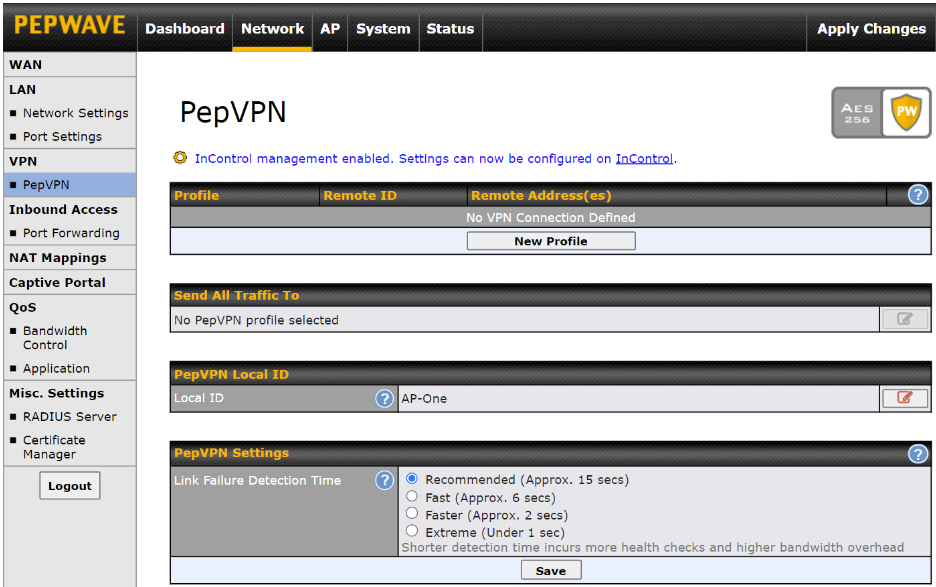
To set up PepVPN, first give your site a local PepVPN ID. To modify an existing local ID,
click on ![]() .
.

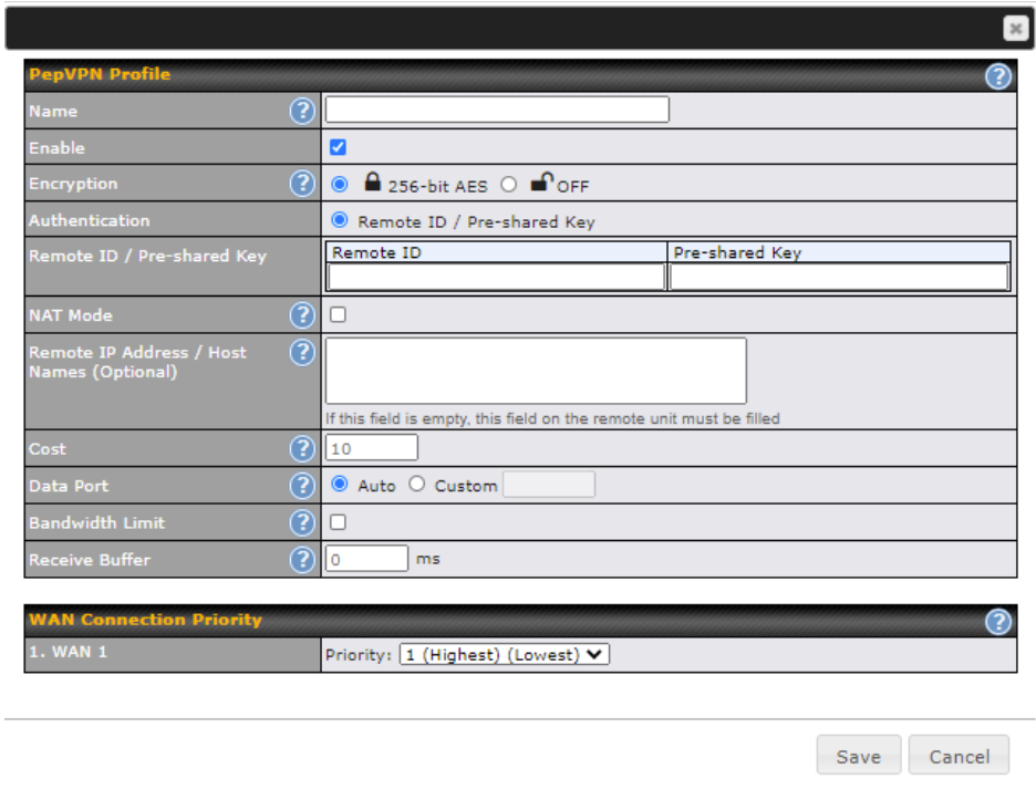
Once you’ve specified a local ID, click the New Profile button to configure PepVPN.

| PepVPN Profile Settings | |
| Name | Enter a name to represent this profile. The name can be any combination of alphanumeric characters (0-9, A-Z, a-z), underscores (_), dashes (-), and/or non-leading/trailing spaces ( ). |
| Enable | Check this box to enable PepVPN. |
| Encryption | By default, VPN traffic is encrypted with 256-bit AES. If Off is selected on both ends of a VPN connection, no encryption will be applied. |
| Authentication | Select Remote ID / Pre-shared Key to specify the method your access point will use to authenticate peers. When selecting Remote ID / Pre-shared Key, be sure to enter a unique peer ID number in the Remote ID field. |
| Remote ID / Pre-shared Key | This optional field becomes available when Remote ID / Pre-shared Key is selected as the Pepwave access point’s VPN Authentication method, as explained above. Pre-shared Key defines the pre-shared key used for this particular VPN connection.
The VPN connection’s session key will be further protected by the pre-shared key. The connection will be up only if the pre-shared keys on each end match. |
| NAT Mode | Check this box to allow the local DHCP server to assign an IP address to the remote peer. When NAT Mode is enabled, all remote traffic over the VPN will be tagged with the assigned IP address using network address translation. |
| Remote IP Address / Host Names (Optional) | If NAT Mode is not enabled, you can enter a remote peer’s WAN IP address or hostname(s) here. If the remote peer uses more than one address, enter only one of them here. Multiple hostnames are allowed and can be separated by a space character or carriage return. Dynamic-DNS host names are also accepted.
This field is optional. With this field filled, the Peplink Balance will initiate connection to each of the remote IP addresses until it succeeds in making a connection. If the field is empty, the Peplink Balance will wait for connection from the remote peer. Therefore, at least one of the two VPN peers must specify this value. Otherwise, VPN connections cannot be established. |
| Cost | Define path cost for this profile. OSPF will determine the best route through the network using the assigned cost.
Default: 10 |
| Data Port | This field specifies the outgoing UDP port number for transporting VPN data. If Default is selected, port 4500 will be used by default. Port 32015 will be used if port 4500 is unavailable. If Custom is selected, you can input a custom outgoing port number between 1 and 65535. |
| Bandwidth Limit | Define maximum download and upload speed to each individual peer. This functionality requires the peer to use PepVPN version 4.0.0 or above. |
| Receive Buffer | Receive Buffer can help to reduce out-of-order packets and jitter, but will introduce extra latency to the tunnel.
Default is 0 ms, which disables the buffer, and the maximum buffer size is 2000 ms. |
| WAN Connection Priority | |
| WAN Connection Priority | If your device supports it, you can specify the priority of WAN connections to be used for making VPN connections. WAN connections set to OFF will never be used. Only available WAN connections with the highest priority will be used.
To enable asymmetric connections, connection mapping to remote WANs, cut-off latency, and packet loss suspension time, click the |

| Send All Traffic To | |
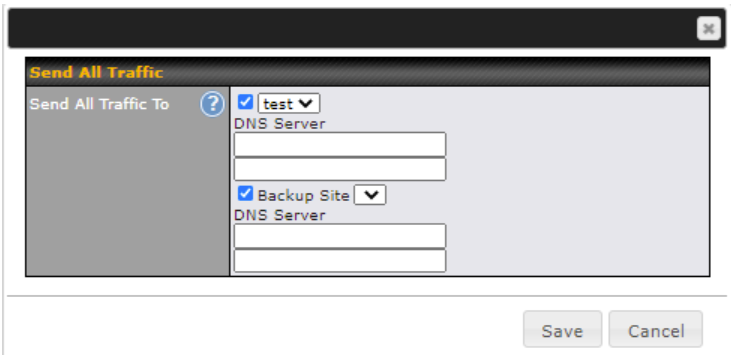
| This feature allows you to redirect all traffic to a specified PepVPN connection. Click the
You could also specify a DNS server to resolve incoming DNS requests. Check the box next to Backup Site to designate a backup SpeedFusion profile that will take over should the main PepVPN connection fail. |

| Link Failure Detection Time | |
| Link Failure Detection Time | The bonded VPN can detect routing failures on the path between two sites over each WAN connection. Failed WAN connections will not be used to route VPN traffic. Health check packets are sent to the remote unit to detect any failure. The more frequently checks are sent, the shorter the detection time, although more bandwidth will be consumed.
When Recommended (default) is selected, a health check packet is sent every five seconds, and the expected detection time is 15 seconds. When Fast is selected, a health check packet is sent every three seconds, and the expected detection time is six seconds. When Faster is selected, a health check packet is sent every second, and the expected detection time is two seconds. When Extreme is selected, a health check packet is sent every 0.1 second, and the expected detection time is less than one second. |
Inbound Access#
*Please note that the following settings will be available only when your access point is operating in Router Mode.
Port Forwarding#
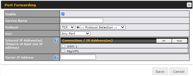
Pepwave access points can act as a firewall that blocks, by default, all inbound access from the Internet. Inbound port forwarding rules can be defined at Network > Inbound Access > Port Forwarding.

To define a new service, click Add Service.
| Port Forwarding Settings | |
| Enable | Check the box to enable the port forwarding profile for Inbound Access. |
| Service Name | This setting identifies the service to the system administrator. Valid values for this setting consist of only alphanumeric and underscore “_” characters. |
| Protocol | The Protocol setting, along with the Port setting, specifies the protocol of the service as TCP, UDP, ICMP, or IP. Traffic that is received by the Pepwave access point via the specified protocol at the specified port(s) is forwarded to the LAN hosts specified by the server setting. Please see below for details on the Port and server settings.
Alternatively, the Protocol Selection Tool drop-down menu can be used to automatically fill in the protocol and a single port number of common Internet services (e.g., HTTP, HTTPS, etc.). After selecting an item from the Protocol Selection Tool drop-down menu, the protocol and port number remain manually modifiable. |
| Port | The Port setting specifies the port(s) that correspond to the service, and can be configured to behave in one of the following manners:
Any Port: all traffic that is received by the Pepwave router via the specified protocol is forwarded to the server specified by the server setting. For example, with IP Protocol set to TCP, and Port set to Any Port, all TCP traffic is forwarded to the configured servers.
|
| Inbound IP Address(es) | This setting specifies the WAN connections and Internet IP address(es) from which the service can be accessed. |
| Server IP Address | This setting specifies the LAN IP address of the server that handles the requests for the service. |
NAT Mapping#
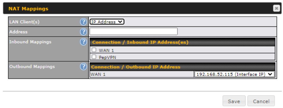
NAT mappings allow IP address mapping of all inbound and outbound NAT’d traffic to and from an internal client IP address. Settings to configure NAT mappings are located at Network > NAT Mappings.
*Please note that the following settings will be available only when your access point is operating in Router Mode.

To add a rule for NAT mappings, click Add NAT Rule.
| NAT Mapping Settings | |
| LAN Client(s) | NAT mapping rules can be defined for a single LAN IP Address, an IP Range, or an IP Network. |
| Address | This is the IP address of the LAN host where the system will map the selected connection IP addresses. |
| Inbound Mappings | This section is to define which inbound IP addresses should be forwarded to the LAN Client(s). |
| Outbound Mappings | This section is to define which IP addresses of each WAN should be used when an IP connection is made from the LAN host to the Internet. |
Captive Portal#

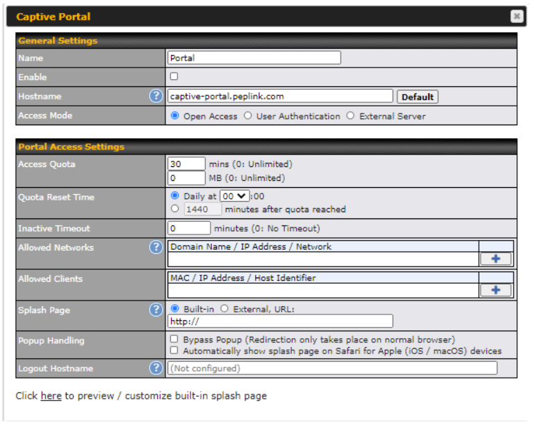
The captive portal serves as a gateway that clients have to pass if they wish to access the Internet using your router. To configure the captive portal, navigate to Network > Captive Portal.
| Captive Portal Settings | |
| Name | Enter a name for the Captive Portal Profile. |
| Enable | Check the Enable box to turn on your access point’s built-in captive portal functionality. |
| Hostname | To customize the portal’s form submission and redirection URL, enter a new URL in this field. |
| Access Mode | Open Access allows clients to freely access your router. User Authentication forces your clients to authenticate before accessing your router. External Server uses the captive portal with HotSpotSystem or CoovaChilli.
As described in the following knowledgebase article: https://forum.peplink.com/t/using-hotspotsystem-wi-fi-on-pepwave-max-routers/ |
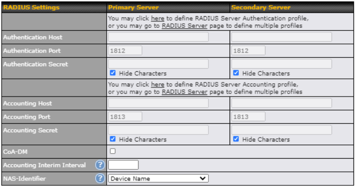
| User Authentication | This authenticates your clients through a RADIUS server. After selecting this option, you will see the following fields:
Fill in the necessary information to complete your connection to the server and enable authentication.
|
| Access Quota | Enter a value in minutes to limit access time on a given login or enter 0 to allow unlimited use time on a single login. Likewise, enter a value in MB for the total bandwidth allowed or enter 0 to allow unlimited bandwidth on a single login. |
| Quota Reset Time | This menu determines how your usage quota resets. Setting it to Daily will reset it at a specified time every day. Setting a number of minutes after quota reached establishes a timer for each user that begins after the quota has been reached. |
| Inactive Timeout | Enter a value in minutes to logout following the specified period of inactivity or enter 0 to disable inactivity logouts. |
| Allowed Networks | To whitelist a network, enter the domain name / IP address here and click the |
| Allowed Clients | To whitelist a client, enter the MAC address / IP address here and click the To delete an existing client from the list of allowed clients, click the |
| Splash Page | Here, you can choose between using the Pepwave access point’s built-in captive portal or redirecting clients to a URL that you define. |
| Popup Handling | Configurable options for popup handling:
|
| Logout Hostname | A hostname that can be used to logout captive portal when being accessed on the browser. |
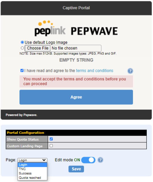
| Customize splash page | Click on the provided link in the Captive Portal Profile to customize the splash page. A new browser tab with a WYSIWYG editor of the splash page will be opened. To edit the content, switch Edit Mode on and select the corresponding elements to edit. |
QoS#
*Please note that the following settings will be available only when your access point is operating in Router Mode.
User Group#
*Please note that the following settings are available only for AP One Rugged (HW2).
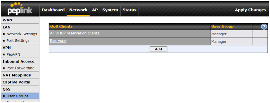
LAN and PPTP clients can be categorized into three user groups – Manager, Staff, and Guest. This table allows you to define rules and assign client IP addresses or subnets to a user group. You can apply different bandwidth and traffic prioritization policies on each user group in the Bandwidth Control and Application sections.
The table is automatically sorted, and the table order signifies the rules’ precedence. The smaller and more specific subnets are put towards the top of the table and have higher precedence; larger and less specific subnets are placed towards the bottom.
Click the Add button to define clients and their user group. Click the ![]() button to remove the defined rule.
button to remove the defined rule.
Two default rules are pre-defined and put at the bottommost. They are All DHCP reservation clients and Everyone, and they cannot be removed. All DHCP reservation clients represents the LAN clients defined in the DHCP Reservation table in the LAN settings page. Everyone represents all clients that are not defined in any rule above. Click on a rule to change its group.

| Add / Edit User Group | |
| Subnet / IP Address | From the drop-down menu, choose whether you are going to define the client(s) by an IP Address or a Subnet. If IP Address is selected, enter a name defined in DHCP reservation table or a LAN client’s IP address. If Subnet is selected, enter a subnet address and specify its subnet mask. |
| User Group | This field is to define which User Group the specified subnet / IP address belongs to. |
Once users have been assigned to a user group, their internet traffic will be restricted by rules defined for that particular group. Please refer to the following two sections for details.
Bandwidth Control#
Group Bandwidth Reservation
Individual Bandwidth Limit
Application
Group Bandwidth Reservation#
*Please note that the following settings are available only for AP One Rugged (HW2).
This section is to define how much minimum bandwidth will be reserved to each user group when a WAN connection is in full load. When this feature is enabled, a slider with two indicators will be shown. You can move the indicators to adjust each group’s weighting. The lower part of the table shows the corresponding reserved download and uploads bandwidth value of each connection.
By default, 50% of bandwidth has been reserved for Manager, 30% for Staff, and 20% for Guest.

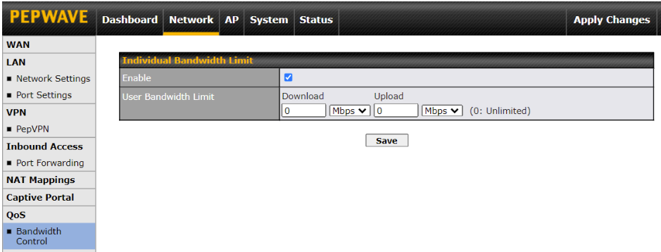
Individual Bandwidth Limit#
The default download and upload limits are set to unlimited (set as 0). This can be changed as necessary to restrict the speeds to individual devices connected to the router, no matter if they are wired or wireless. Note that this limit is applied to all connected devices.
Application#
You can choose whether to apply the same prioritization settings to all user groups or customize the settings for each group.

Define the priority level of selected applications. Available priorities are ↑High,━ Normal, and ↓Low. Applications not defined in the table are assigned a “Normal” priority level.
Pepwave access points can detect various application traffic by inspecting the packets’ content. Select an application by choosing a supported application, or by manually defining a custom application. The priority preference of supported applications is placed at the top of the table. Custom applications are at the bottom.

Click the Add button to define a custom application. Click the ![]() button in the Action column to delete the custom application in the corresponding row.
button in the Action column to delete the custom application in the corresponding row.

When Supported Applications is selected, the Pepwave access point will inspect network traffic and prioritize the selected applications. Alternatively, you can select Custom Applications and define the application by providing the protocol, scope, port number, and DSCP value.

DSL / Cable Optimization

DSL/cable-based WAN connections normally have their upload bandwidth set lower than their download bandwidth. When a DSL/cable circuit’s uplink is congested, the download bandwidth will be affected. Users will not be able to download data at full speed until the uplink becomes less congested. The DSL/Cable Optimization can relieve such issues. When it is enabled, the download speed will be less affected by the upload traffic.
PepVPN Traffic Optimization
Check the box to enable PepVPN traffic to have the highest priority when the WAN is congested.
Misc. Settings#
Radius Server#
RADIUS Server settings are located at Network > Misc. Settings > RADIUS Server.

Click New Profile to display the following screen:

| Authentication Server | |
| Name | This field is for specifying a name to represent this profile. |
| Host | Specifies the IP address or hostname of the RADIUS server host. |
| Port | This setting specifies the UDP destination port for authentication requests. By default, the port number is 1812. |
| Secret | This field is for entering the secret key for communicating to the RADIUS server. |
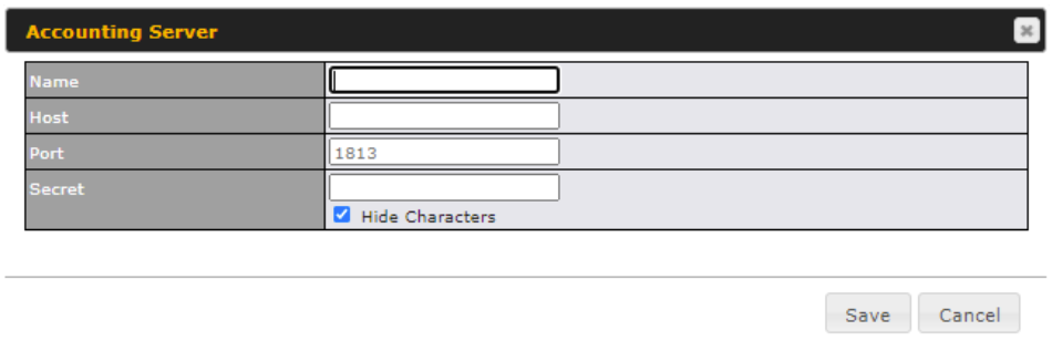
| Accounting Server | |
| Name | This field is for specifying a name to represent this profile. |
| Host | Specifies the IP address or hostname of the RADIUS server host. |
| Port | This setting specifies the UDP destination port for authentication requests. By default, the port number is 1813. |
| Secret | This field is for entering the secret key for communicating to the RADIUS server. |
Certificate Manager#
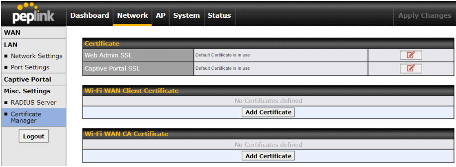
This section allows for certificates to be assigned to the Web Admin SSL, Captive Portal SSL and Wi-Fi WAN (Client and CA).
The following knowledge base article describes how to create self-signed certificates and import it to a Peplink Product.
Ignition Sensing#
The GPIO and Ignition sensing feature are supported by AP One Rugged (HW2).
Ignition Sensing detects the ignition signal status of a vehicle it is installed in.
This feature allows the cellular router to start up or shut down when the engine of that vehicle is started or turned off.
The time delay setting between ignition off and power down of the router is a configurable setting, which allows the router to stay on for a period of time after the engine of a vehicle is turned off.
Ignition Sensing installation
| Function | Colour Wire | ||
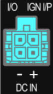 |
I/O | Digital Input/Digital Output/ Analog Input | Brown |
| IGN I/P | Digital Input / Ignition Sensing | Orange | |
| DC IN – |
connected to permanent negative feed (ground) | Black | |
|
DC IN + |
connected to permanent positive feed (power) | Red | |
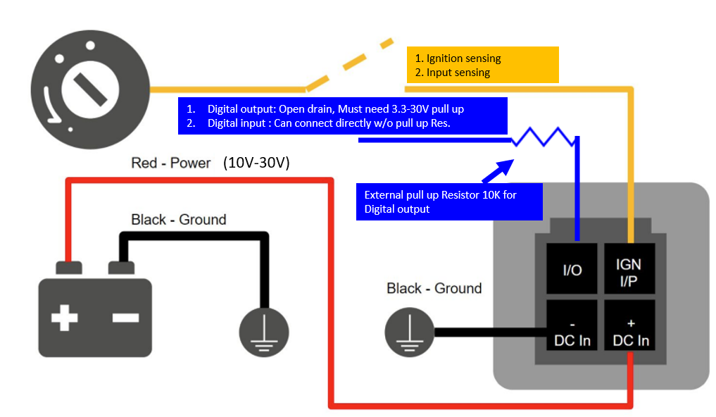
Connectivity diagram for devices with 4-pin connector
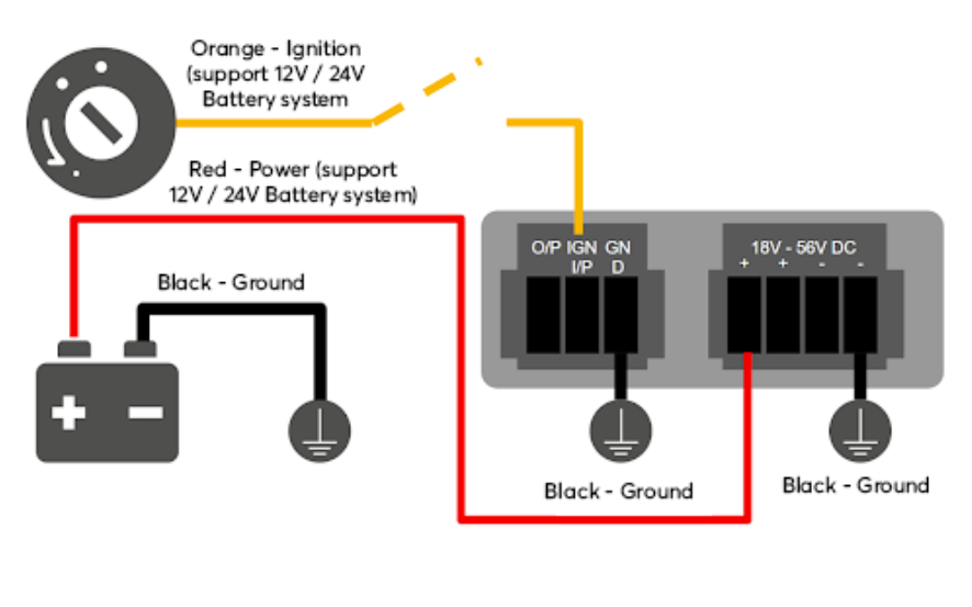
Connectivity diagram for devices with terminal block connection
GPIO Menu
Note: This feature is applicable for certain models that come with a GPIO interface.
Ignition Sensing options can be found in Advanced > GPIO.
The configurable option for Ignition Input is Delay; the time in seconds that the router stays powered on after the ignition is turned off.
a.) Ignition sensing: 9-30V active high for IGN purpose
b.) Input Sensing: I/O input

The O/P (connected to the I/O pin on a 4 pin connector) can be configured as a digital input, a digital output, or an analog input.
Digital Input – the connection supports input sensing; it reads the external input and determines if the settings should be ‘High’ (on) or ‘Low’ (off).
Digital Output – when there is a healthy WAN connection, the output pin is marked as ‘High’ (on). Otherwise, it will be marked as ‘Low’ (off).
a.) Digital output:
Open drain for IO output. It is required to add an external pull up resistor of 10K for 3.3-30V pull up voltage.
(DO NOT exceed 250mA)
3.3-30V active high, 0.05-0.5V active low(mapping to 3.3-30V pull up voltage)
b.) Digital input: I/O input

Note: The Digital Output state (on/off) upon rebooting the device may vary depending on the model, eg. MAX BR1 MK2 = Persistent; MAX Transit Mini with ContentHub = Reset to default, etc.
Analog Input – to be confirmed. In most cases, it should read the external input and determine the voltage level.
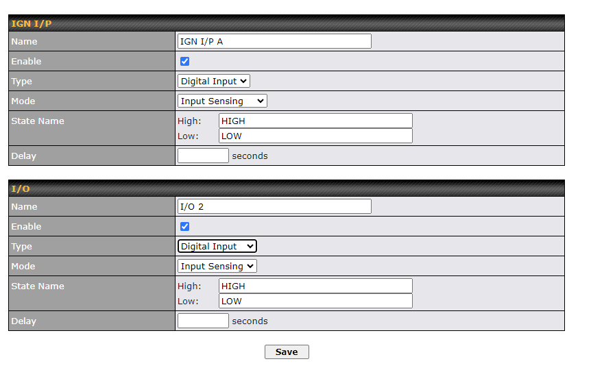
As of firmware 3.9.4, you can now configure a custom name for GPIO.
- Name: Name to be shown in the Event Log
- State Name: Tag name that represents the GPIO state to be shown in the Event Log
Ch7. AP Tab#
AP#
Use the controls on the AP tab to set the wireless SSID, AP settings and Mesh, as well as wireless distribution system (WDS) settings.
Wireless SSID#

Wireless network settings, including the name of the network (SSID) and security policy, can be defined and managed in this section.
Click New SSID to create a new network profile, or click the existing network profile to modify its settings.
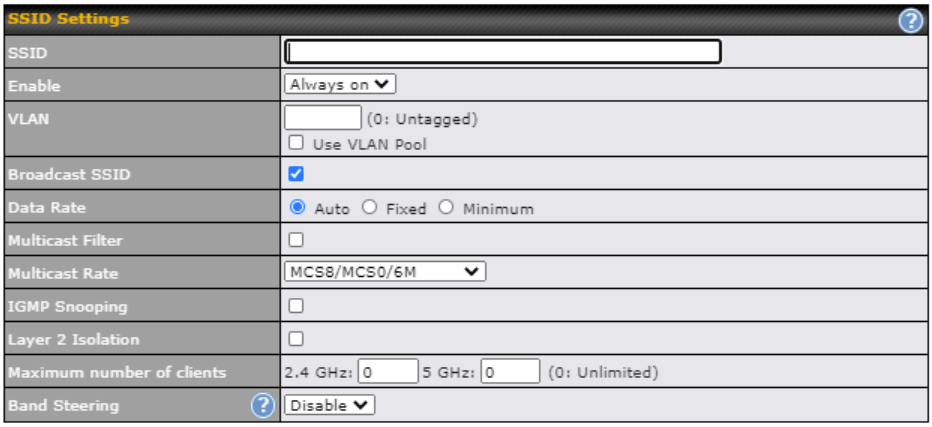
| SSID Settings | |
| SSID | This setting specifies the router’s SSID that Wi-Fi clients will see when scanning for Wi-Fi signals.. |
| Enable | Click the drop-down menu to choose predefined schedules as your starting point. Please note that upon selection, previous changes on the schedule map will be deleted. |
| VLAN | This setting specifies the VLAN ID to be tagged on all outgoing packets generated from this wireless network (i.e. packets that travel from the Wi-Fi segment through your access point to the ethernet segment via the LAN port). If 802.1x is enabled and a per-user VLAN ID is specified in the authentication reply from the Radius server, then the value specified by the default VLAN ID will be overridden. The default value of this setting is 0, which means that VLAN tagging is disabled (instead of tagged with zero).
If Use VLAN Pool is enabled, enter the VLAN pool value specified in VLAN. |
| Broadcast SSID | This setting specifies whether or not Wi-Fi clients can scan the SSID of this wireless network. Broadcast SSID is enabled by default. |
| Data Rate | Select Auto to allow your access point to set the data rate automatically, or select Fixed or Minimum to choose a set rate from a drop-down menu. |
| Multicast Filter | This setting enables the filtering of multicast network traffic to the wireless SSID. |
| Multicast Rate | This setting specifies the transmit rate to be used for sending multicast network traffic. |
| IGMP Snooping | To allow your access point to convert multicast traffic to unicast traffic for associated clients, select this option. |
| Layer 2 Isolation | Layer 2 refers to the second layer in the ISO Open System Interconnect model. When this option is enabled, it will block communication between Wi-Fi clients within the same VLAN, SSID or subnet, as a security measure that best suits a company Guest/Visitor Wi-Fi access scenario.
Do refer to this link (https://forum.peplink.com/t/lan-isolation-with-balance30-and-ap-one-ac-minihelp-needed/3914/4) for visual illustration of the feature. By default, the setting is disabled. |
| Maximum Number of Clients | The maximum number of clients that can simultaneously connect to your access point, or enter 0 to allow unlimited Wi-Fi clients. |
| Band Steering | This setting, shown below, allows you to reduce 2.4 GHz band overcrowding, AP with band steering steers clients capable of 5 GHz operation to 5 GHz frequency.
Force – Clients capable of 5 GHz operation are only offered with 5 GHz frequency.
|

| Security Settings | |
| Security Policy | This setting configures the wireless authentication and encryption methods. Available options are:
To allow any Wi-Fi client to access your AP without authentication, select Open (No Encryption). Details on each of the available authentication methods follow. |

| Enhanced Open (OWE) | |
| Transition Mode | With the option enabled, legacy clients will be able to connect in Open mode. With the option disabled, legacy clients will not be able to connect. OWE-supported clients will always connect in OWE mode. |

| WPA3 – Personal | |
| Shared Key | Enter a passphrase of between 8 and 63 alphanumeric characters to create a passphrase used for data encryption and authentication. Click Hide / Show Characters to toggle visibility. |
| Fast Transition | Fast Transition [802.11r] When this option is ticked, the transition process of a mobile client is improved as it moves between access points. |

| WPA3 – Enterprise | |
| 802.1X Version | Choose v1 or v2 of the 802.1x EAPOL. When v1 is selected, both v1 and v2 clients can associate with the access point. When v2 is selected, only v2 clients can associate with the access point. Most modern wireless clients support v2. For stations that do not support v2, select v1. The default is v2. |
| Fast Transition | Fast Transition [802.11r] When this option is ticked, the transition process of a mobile client is improved as it moves between access points. |

| WPA2/WPA3 – Personal | |
| Shared Key | Enter a passphrase of between 8 and 63 alphanumeric characters to create a passphrase used for data encryption and authentication. Click Hide / Show Characters to toggle visibility. |
| Management Frame Protection | This feature protects stations against forged management frames spoofed from other devices. Frames that are protected include Disassociation, Deauthentication and QoS Action. |
| Fast Transition | Fast Transition [802.11r] When this option is ticked, the transition process of a mobile client is improved as it moves between access points. |

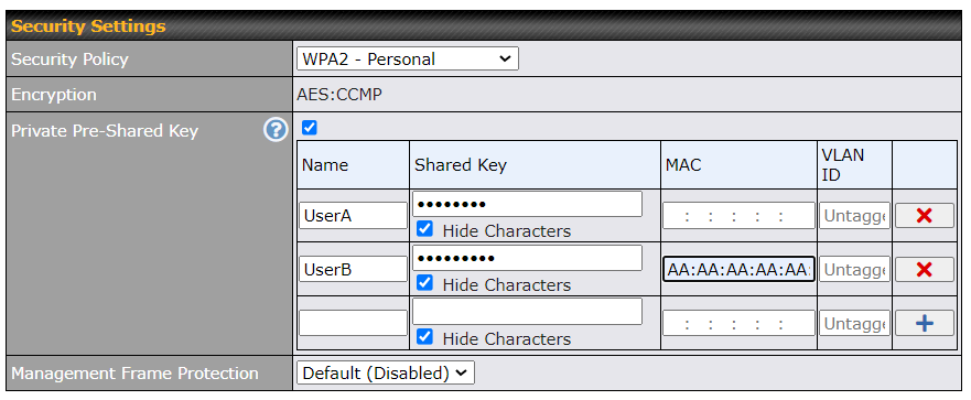
| WPA2 – Personal | |||||||||
| Private Shared Key | Enable the Private Pre-Shared Key (PPSK) option to set unique pre-shared keys for individual users or groups on the same SSID. Please provide the following information for each user or group:
* Each “Shared Key + MAC” combination must be unique in a different profile. |
||||||||
| Shared Key | Enter a passphrase of between 8 and 63 alphanumeric characters to create a passphrase used for data encryption and authentication. Click Hide / Show Characters to toggle visibility. | ||||||||
| Management Frame Protection | This feature protects stations against forged management frames spoofed from other devices. Frames that are protected include Disassociation, Deauthentication and QoS Action. | ||||||||
| Fast Transition | Fast Transition
[802.11r] When this option is ticked, the transition process of a mobile client is improved as it moves between access points. |
||||||||

| WPA2 – Enterprise | |
| 802.1X Version | Choose v1 or v2 of the 802.1x EAPOL. When v1 is selected, both v1 and v2 clients can associate with the access point. When v2 is selected, only v2 clients can associate with the access point. Most modern wireless clients support v2. For stations that do not support v2, select v1. The default is v2. |
| Management Frame Protection | This feature protects stations against forged management frames spoofed from other devices. Frames that are protected include Disassociation, Deauthentication and QoS Action. |
| Fast Transition | Fast Transition [802.11r] When this option is ticked, the transition process of a mobile client is improved as it moves between access points. |


| WPA/WPA2 – Personal | |||||||||
| Private Shared Key | Enable the Private Pre-Shared Key (PPSK) option to set unique pre-shared keys for individual users or groups on the same SSID. Please provide the following information for each user or group:
* Each “Shared Key + MAC” combination must be unique in a different profile. |
||||||||
| Shared Key | Enter a passphrase of between 8 and 63 alphanumeric characters to create a passphrase used for data encryption and authentication. Click Hide / Show Characters to toggle visibility. | ||||||||
| Management Frame Protection | This feature protects stations against forged management frames spoofed from other devices. Frames that are protected include Disassociation, Deauthentication and QoS Action. | ||||||||

| WPA/WPA2 – Enterprise | |
| 802.1X Version | Choose v1 or v2 of the 802.1x EAPOL. When v1 is selected, both v1 and v2 clients can associate with the access point. When v2 is selected, only v2 clients can associate with the access point. Most modern wireless clients support v2. For stations that do not support v2, select v1. The default is v2. |
| Management Frame Protection | This feature protects stations against forged management frames spoofed from other devices. Frames that are protected include Disassociation, Deauthentication and QoS Action. |

| Access Control | |
| Restricted Mode | The settings allow the administrator to control access using Mac address filtering. Available options are None, Deny all except listed, Accept all except listed, and RADIUS MAC Authentication. |
| MAC Address List | Connections coming from the MAC addresses in this list will be either denied or accepted based on the option selected in the previous field. |
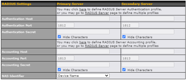
| RADIUS Server Settings | |
| Host | Enter the IP address of the primary RADIUS server and, if applicable, the secondary RADIUS server. |
| Secret | Enter the RADIUS shared secret for the primary server and, if applicable, the secondary RADIUS server. |
| Authentication Port | Enter the UDP authentication port(s) used by your RADIUS server(s) or click the Default button to enter 1812. |
| Accounting Port | Enter the UDP accounting port(s) used by your RADIUS server(s) or click the Default button to enter 1813. |
| NAS-Identifier | Information added to access requests to identify the NAS. Select Device Name, LAN MAC Address, Device Serial Number or enter a Custom Value When the NAS ID is not defined, the Device Name will be used as the NAS ID in RADIUS requests. |

| Guest Protect | |
| Block All Private IP | Check this box to block access from the Private IP. |
| Custom Subnet | To specify a subnet to block, enter the IP address and choose a subnet mask from the drop-down menu. To add the blocked subnet, click |
| Block Exception | To create an exception to a blocked subnet (above), enter the IP address and choose a subnet mask from the drop-down menu. To add the exception, click |

| Bandwidth Management | |
| Upstream Limit | Enter a value in kbps to limit the wireless network’s upstream bandwidth.
Enter 0 to allow unlimited upstream bandwidth. |
| Downstream Limit | Enter a value in kbps to limit the wireless network’s downstream bandwidth.
Enter 0 to allow unlimited downstream bandwidth. |
| Client Upstream Limit | Enter a value in kbps to limit connected clients’ upstream bandwidth.
Enter 0 to allow unlimited upstream bandwidth. |
| Client Downstream Limit | Enter a value in kbps to limit connected clients’ downstream bandwidth. Enter 0 to allow unlimited downstream bandwidth. |

| Firewall Settings | |
| Firewall Mode | Choose Flexible – Allow all except… or Lockdown – Block all except… to turn on the firewall, then create rules for the firewall exceptions by clicking |

| Firewall Rule | |
| Name | Enter a descriptive name for the firewall rule in this field. |
| Type | Choose Port, IP Network, MAC Address or Domain Name to allow or deny traffic from any of those identifiers. Depending on the option chosen, the following fields will vary. |
| Port | Choose TCP or UDP from the Protocol drop-down menu to allow or deny traffic using either of those protocols. From the Port drop-down menu, choose Any Port to allow or deny TCP or UDP traffic on any port. Choose Single Port and then enter a port number in the provided field to allow or block TCP or UDP traffic from that port only. You can also choose Port Range and enter a range of ports in the provided fields to allow or deny TCP or UDP traffic from the specified port range. |
| IP Network | If you have chosen IP Network as your firewall rule type, enter the IP address and subnet mask identifying the subnet to allow or deny. |
| MAC Address | If you have chosen MAC Address as your firewall rule type, enter the MAC address identifying the machine to allow or deny. |
| Domain Name | If you have chosen Domain Name as your firewall rule type, enter the Domain Name identifying the machine to allow or deny. |
Wireless Mesh#
Mesh support enables an access point (AP) to connect wirelessly to other wired mesh APs, providing redundancy in the event of AP failure. Mesh support is available for Wi-Fi networks 802.11ac (Wi-Fi 5) and above.
Please note that the AP’s Mesh settings need to match the Mesh ID and Shared Key of the selected frequency band in order for the AP to join the network.

To create a new Wireless Mesh profile, go to AP > Mesh, and click Add.
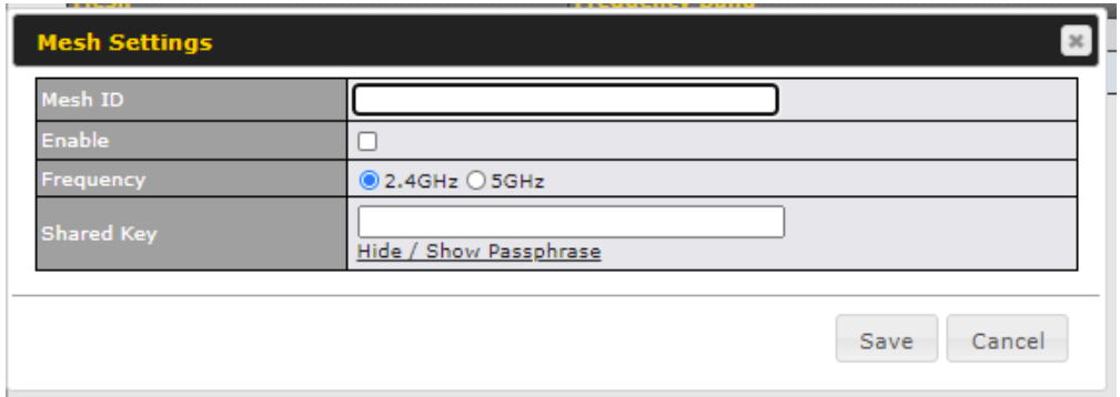
| Mesh Settings | |
| Mesh ID | Enter a name to represent the Mesh profile. |
| Enable | Check the box to enable the Mesh Profile. |
| Frequency | Select the 2.4GHz or 5GHz frequency to be used. |
| Shared Key | Enter the shared key in the text field. Please note that it needs to match the shared keys of the other APs in the Mesh.
Click Hide / Show Passphrase to toggle visibility. |
WDS#
A wireless distribution system (WDS) provides a way to link access points together when wired or cabled connections are not feasible or desirable. A WDS can also extend wireless network coverage for wireless clients. Please note that your access point’s channel setting should not be set to Auto when using WDS.

To create a new WDS, go to AP > WDS, and click Add.

| WDS | |
| MAC Address | Enter the MAC address of the access point with which to form a WDS link. |
| Enable | Check this box to enable WDS. |
| Frequency | Select the frequency (2.4GHz or 5GHz) for WDS peer connection. |
| Encryption | Select AES to enable encryption for WDS peer connections. Selecting None disables encryption. |
Settings#
Basic access point operation settings, such as the protocol and channels used, as well as scanning intervals and other advanced settings can be defined and managed in this section.
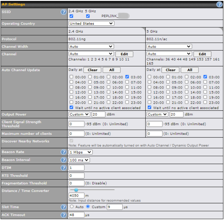
| AP Settings | |
| SSID | Select if an SSID is broadcasting on 2.4 GHz, 5 GHz or both bands. |
| Operating Country | This drop-down menu specifies the national / regional regulations the AP should follow. If a North American region is selected, RF channels 1 to 11 will be available and the maximum transmission power will be 26 dBm (400 mW). If a European region is selected, RF channels 1 to 13 will be available. The maximum transmission power will be 20 dBm (100 mW). NOTE: Users are required to choose an option suitable to local laws and regulations. Per FCC regulation, the country selection is not available on all models marketed in the US. All US models are fixed to US channels only. |
| Protocol | Choose 802.11ng or 802.11n/ac as your access point’s Wi-Fi protocol.
The AP One AC Mini provides the 802.11ng protocol for the 2.4 GHz band and the 802.11n/ac protocol for the 5GHz band, as shown below. |
| Channel Width | This option defines which channel width the radio will use: 20MHz – Supports clients with 20MHz capability. This is the default value for 802.11ng. 40MHz – Supports clients with 20/40MHz capability. 20/40MHz – Supports clients with 20/40 MHz capability. The radio will fall back to 20MHz if it detects APs that only support 20MHz. This is the default value for 802.11na. 80MHz – Supports clients with 20/40/80MHz capability. This is the default value for 802.11n/ac. |
| Channel | This drop-down menu selects the 2.4 GHz and 5GHz 802.11 channels to be used.
When Auto is selected, the system will perform channel scanning based on the scheduled time set and choose the most suitable channel automatically. |
| Output Power | This option enables the configuration of transmission power. Choose between: Max / High / Medium / Low / Custom. Max is the Maximum power supported for that country or Maximum power supported for the device (whichever is the smaller value). High is 3dBm below the max value. Medium is 3dBm below high value. Low is 3 dBm below Medium value. |
| Client Signal Strength Threshold | This field determines the minimum acceptable client signal strength, specified in decibel-milliwatts (dBm). If client signal strength does not meet this minimum, the client will not be allowed to connect. |
| Maximum number of Clients | Enter the maximum clients that can simultaneously connect to your access point or set the value to 0 to allow unlimited clients. |
| Discover Nearby Networks | Check this box to enable network discovery. Note that setting Channel to Auto will activate this feature automatically. |
| Beacon Rate | This drop-down menu provides the option to send beacons in different transmit bit rates. The bit rates are 1 Mbps, 2 Mbps, 5.5 Mbps, 6 Mbps, and 11 Mbps. |
| Beacon Interval | Set the time between each beacon send. Available options are 100 ms, 250 ms, and 500 ms. |
| DTIM | Set the frequency for the beacon to include delivery traffic indication messages (DTIM). The interval unit is measured in milliseconds. |
| RTS Threshold | Set the minimum packet size for your access point to send an RTS using the RTS/CTS handshake. Setting 0 disables this feature. |
| Fragmentation Threshold | Enter a value to limit the maximum frame size, which can improve performance. |
| Distance / Time Convertor | This slider and text entry field can be used to interactively set slot time. |
| Slot Time | This field provides the option to modify the unit wait time before your access point transmits. The default value is 9μs. |
| ACK Timeout | Set the wait time to receive an acknowledgement packet before retransmitting. The default value is 48μs. |
Status#
Access Point#
A detailed breakdown of data usage and number of clients for each AP is available at AP > Status > Access Point.
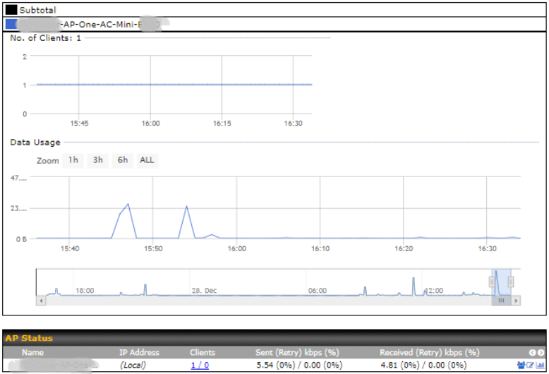
This table shows the detailed information on each AP, including channel, number of clients, power, upload traffic, and download traffic. On the right of the table, you will see the following icons: ![]()
Click the ![]() icon to see a usage table for each client:
icon to see a usage table for each client:

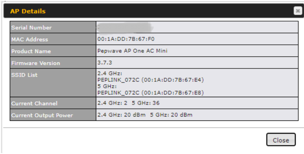
Click the ![]() icon to configure AP details.
icon to configure AP details.
Click the ![]() icon to see a graph displaying usage.
icon to see a graph displaying usage.

Click any point on the graphs to display detailed usage and client information for that device, using that SSID, at that point in time. On the Data Usage by drop-down menu, you can display the information by SSID or by AP send/receive rate.
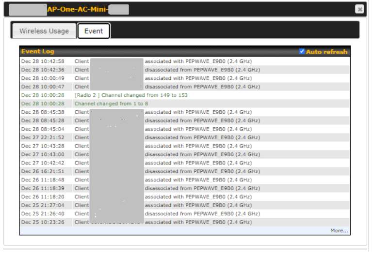
You may click the Event tab which is next to Wireless Usage to view a detailed event log for that particular device.
Wireless SSID#
In-depth SSID reports are available under AP > Status > Wireless SSID.
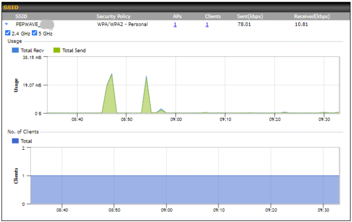
Click the blue arrow on any SSID to obtain more detailed usage information on each SSID.
Wireless Client#
You can search for specific Wi-Fi users by navigating to AP > Status > Wireless Client.
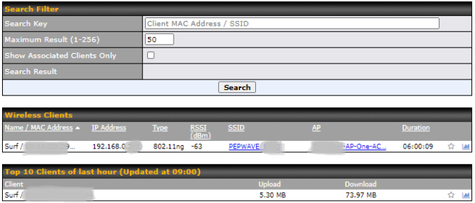
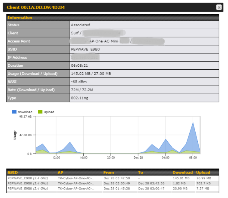
Wireless Client allows you to be able to see your network’s heaviest users as well as search for specific users. Click the ![]() icon to bookmark specific users, and click the
icon to bookmark specific users, and click the ![]() icon for additional details about each user.
icon for additional details about each user.
Mesh / WDS#

WDS link information
WDS link information allows you to monitor the status of your wireless distribution system (WDS) or mesh and track activity by MAC address. This table shows detailed information for each AP, including protocol, transmit rate (sent/received), signal strength, and duration.
Mesh link information
Mesh link information allows you to monitor the status of each mesh link (node to node) in the mesh network. This table shows detailed information for each mesh link, including Node A, Node B, Link Type, Tx/Rx Rate, and Signal on both nodes.

Nearby Device#
A listing of near devices can be accessed by navigating to AP > Status > Nearby Device.
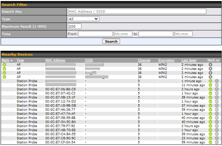
| Nearby Devices | |
| Hovering over the device MAC address will result in a popup with information on how this device was detected. You may click the |
Event Log#
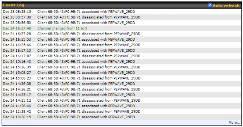
You can access the AP Controller Event log by navigating to AP > Status > Event Log.

| Event Log | |
| This event log displays all activity on your AP network, down to the client level. You can use the filter box to search by MAC address, SSID, AP Serial Number, or AP Profile name. Click View Alerts to see only alerts, and click the More… link for additional records. |
Ch8. System Tab#
Admin Security#
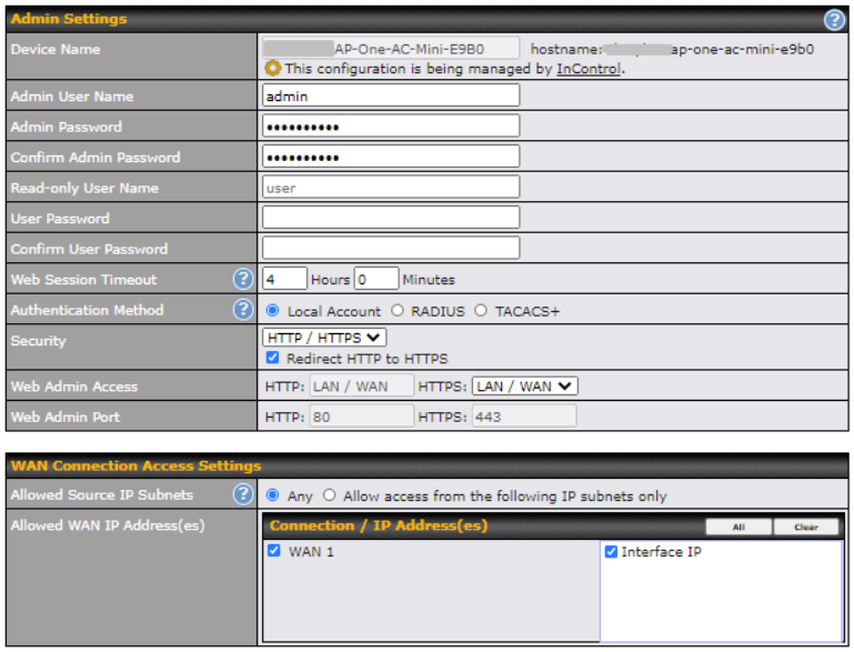
| Admin Settings | |||||||||||||||||||||||
| Devicer Name | This field allows you to define a name for this Peplink Balance unit. By default, Device Name is set as Model_XXXX, where XXXX refers to the last 4 digits of the serial number of that unit. |
||||||||||||||||||||||
| Admin User Name | Admin User Name is set as admin by default, but can be changed. | ||||||||||||||||||||||
| Admin Password | This field allows you to specify a new administrator password. | ||||||||||||||||||||||
| Confirm Admin Password | This field allows you to confirm the new administrator password. | ||||||||||||||||||||||
| Read-only User Name | Read-only User Name is set as user by default, but can be changed, if desired. | ||||||||||||||||||||||
| User Password | This field allows you to specify a new user password. Once the user password is set, the read-only user feature will be enabled. | ||||||||||||||||||||||
| Confirm User Password | This field allows you to confirm the new user password. | ||||||||||||||||||||||
| Web Session Timeout | A web login session will be logged out automatically when it has been idle longer than the Web Session Timeout.
Unlimited session timeout: 0 hours 0 minutes. |
||||||||||||||||||||||
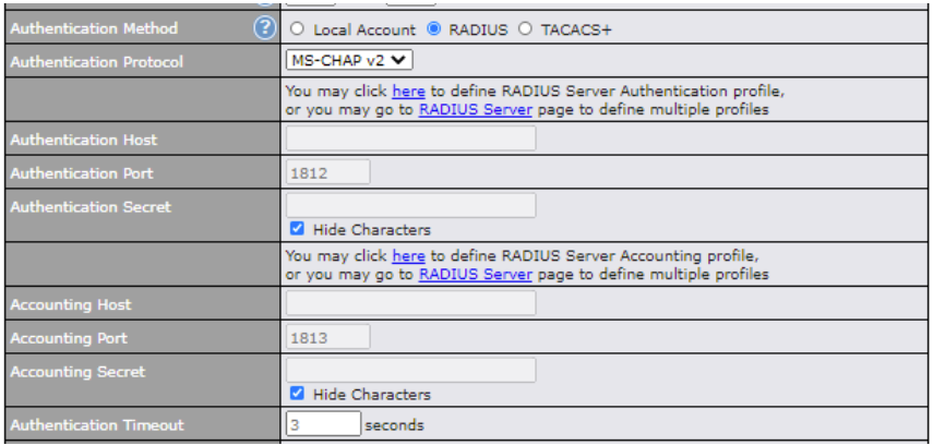
| Authentication Method | When External Authentication is selected, the web admin will authenticate using the corresponding external server. Authenticated users are treated as either “admin” with full read-write permission or “user” with read-only access. Local admin and user accounts will be disabled. However, when the device is not able to communicate with the external server, local accounts are enabled to allow emergency access. By default, it is set to Local Account. Available options:
|
||||||||||||||||||||||
| Security | This option is for specifying the protocol(s) through which the web admin interface can be accessed:
|
||||||||||||||||||||||
| Web Admin Access | This option is for specifying the network interfaces through which the web admin interface can be accessed:
If LAN/WAN is chosen, the WAN Connection Access Settings form will be displayed. |
||||||||||||||||||||||
| Web Admin Port | This field is for specifying the port number on which the web admin interface can be accessed. | ||||||||||||||||||||||
| Allowed Source IP Subnets | This option is for specifying the IP subnets through which the web admin interface can be accessed.
The allowed IP subnet addresses should be entered into this text area. Each IP subnet must be in form of w.x.y.z/m, where w.x.y.z is an IP address (e.g. 192.168.0.0), and m is the subnet mask in CIDR format, which is between 0 and 32 inclusively (e.g. 192.168.0.0/24). To define multiple subnets, separate each IP subnet one in a line. For example:
|
||||||||||||||||||||||
| Allowed WAN IP Address(es) | This field allows you to select the WAN IP address(es) the web server should connect to. | ||||||||||||||||||||||
Operating Mode#

You can select the operating mode you want to use for the access point device. The available options are:
- Router Mode
- Bridge Mode
- Bridge Mode, without LAN IP address
Firmware#

There are two ways to upgrade the unit. The first method is through an online download. The second method is to upload a firmware file manually.
To perform an online download, click on the Check for Firmware button. The access point will check online for new firmware. If new firmware is available, the access point automatically downloads the firmware. The rest of the upgrade process will be automatically initiated.
You may also download a firmware image from the Peplink website and update the unit manually. To update using a firmware image, click Choose File to select the firmware file from the local computer, and then click Manual Upgrade to send the firmware to the access point. It will then automatically initiate the firmware upgrade process.
Please note that all devices can store two different firmware versions in two different partitions. A firmware upgrade will always replace the inactive partition. If you want to keep the inactive firmware, you can simply reboot your device with the inactive firmware and then perform the firmware upgrade.
| Firmware Upgrade Status |
Status LED information during firmware upgrade:
|
| Important Note |
| The firmware upgrade process may not necessarily preserve the previous configuration, and the behavior varies on a case-by-case basis. Consult the release notes for the particular firmware version before installing. Do not disconnect the power during the firmware upgrade process. Do not attempt to upload a non-firmware file or a firmware file that is not supported by Peplink. Upgrading the Peplink Balance with an invalid firmware file will damage the unit and may void the warranty. |
Time#

The time server functionality enables the system clock of the access point to be synchronized with a specified time server. The settings for time server configuration are located at System > Time.
| Time Settings | |
| Time Zone | This specifies the time zone (along with the corresponding Daylight Savings Time scheme) in which Pepwave AP operates. The Time Zone value affects the time stamps in the event log of the Pepwave AP and e-mail notifications. Check Show all to show all time zone options. |
| Time Server | This setting specifies the NTP network time server to be utilized by the Pepwave AP. |
Schedule#

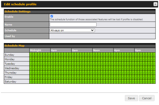
Enable and disable different functions such as WAN connections and SSID at different times, based on a user-scheduled configuration profile. The settings for this are located at System > Schedule.
Click on New Schedule to begin the schedule profile.
| Edit Schedule Profile | |
| Enable | Click this checkbox to enable this schedule profile. Note that if this is disabled, then any associated features will also have their scheduling disabled. |
| Name | Enter your desired name for this particular schedule profile. |
| Schedule | Click the drop-down menu to choose from predefined schedules as your starting point. Please note that upon selecting a predefined schedule, previous changes on the schedule map will be deleted. |
| Schedule Map | Click on the desired times to enable features for that time period. You can hold down your mouse button for faster entry. |
Email Notification#
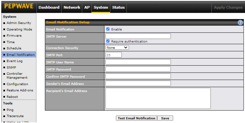
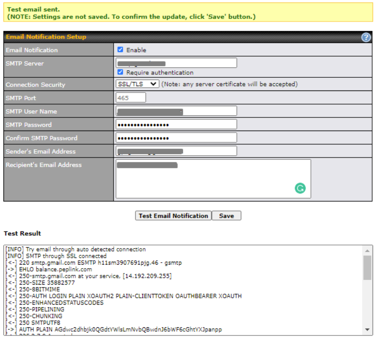
Email notification functionality provides a system administrator with up-to-date information on network status. The settings for configuring email notifications are found at System > Email Notification.
| Email Notification Settings | |
| Email Notification | This setting specifies whether or not to enable email notification.
If Enable is checked, the Pepwave AP will send email messages to system administrators when the WAN status changes or when new firmware is available. If Enable is unchecked, email notification is disabled and the Pepwave AP will not send email messages. |
| SMTP Server | This setting specifies the SMTP server to be used for sending the email notifications. If the server requires authentication, check Require authentication. |
| Connection Security | This setting specifies via a drop-down menu one of the following valid connection security options:
When a connection security option is selected, the SMTP Port will automatically set a default port number. |
| SMTP Port | This field is for specifying the SMTP port number. By default, this is set to 25.
When STARTTLS is selected, the default port number will be set to 587. When SSL/TTS is selected, the default port number will be set to 465. You may customize the port number by editing this field. |
| SMTP User Name / Password | This setting specifies the SMTP username and password for accessing the SMTP Server to send the email notifications. These fields are only visible when the Require authentication box is checked in the SMTP Server setting. |
| Confirm SMTP Password | This field allows you to verify that the SMTP password matches (if a password is provided in the SMTP Password field). |
| Sender’s Email Address | This setting specifies the email address that the Pepwave AP will send reports from. |
| Recipient’s Email Address | This setting specifies the email address(es) to which the Pepwave AP will send email notifications. For multiple recipients, separate each email address using the Enter key. |
After you have finished setting up email notifications, you may click the Test Email Notification button to test the settings before saving them. After Test Email Notification is clicked, you will see this screen to confirm the settings:

Click Send Test Notification to send the test email with the current settings. In a few seconds, you will see a message with detailed test results.
Event Log#

Event log functionality enables event logging at a specified remote syslog server. The settings for configuring the remote system log can be found at System > Event Log.
| Remote Syslog Settings | |
| Remote Syslog | This setting specifies whether or not to log events at the specified remote syslog server. |
| Remote Syslog Host | This setting specifies the IP address or hostname of the remote syslog server. Default Port is: 514 |
| Push Event | The Pepwave AP can also send push notifications to mobile devices that have our Mobile Router Utility installed. Check the box to activate this feature.
For more information on the Router Utility, go to: www.peplink.com/products/router-utility |
SNMP#
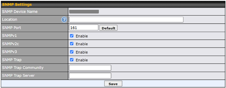
SNMP or simple network management protocol is an open standard that can be used to collect information about the Pepwave AP unit. SNMP configuration is located at System > SNMP.
| SNMP Settings | |
| SNMP Device Name | This field displays the router name defined at System > Admin Security. |
| SNMP Port | This option specifies the port which SNMP will use. The default port is 161. |
| SNMPv1 | This option allows you to enable SNMP version 1. |
| SNMPv2c | This option allows you to enable SNMP version 2c. |
| SNMPv3 | This option allows you to enable SNMP version 3. |
| SNMP Trap | This option allows you to enable SNMP Trap. If enabled, the following entry fields will appear. |
| SNMP Trap Community | This setting specifies the SNMP Trap community name. |
| SNMP Trap Server | Enter the IP address of the SNMP Trap server. |
To add a community for either SNMPv1 or SNMPv2c, click the Add SNMP Community button in the Community Name table, upon which the following screen is displayed:

| SNMP Community Settings | |
| Community Name | This setting specifies the SNMP community name. |
| Allowed Network | This setting specifies a subnet from which access to the SNMP server is allowed. Enter the subnet address here (e.g. 192.168.1.0) and select the appropriate subnet mask. |
To define a user name for SNMPv3, click Add SNMP User in the SNMPv3 User Name table, upon which the following screen is displayed:

| SNMPv3 User Settings | |
| User Name | This setting specifies a user name to be used in SNMPv3. |
| Authentication Protocol | This setting specifies via a drop-down menu one of the following valid authentication protocols:
When MD5 or SHA is selected, an entry field will appear for the password. |
| Privacy | This setting specifies via a drop-down menu one of the following valid privacy protocols:
When DES or AES is selected, an entry field will appear for the password. |
Controller Management#
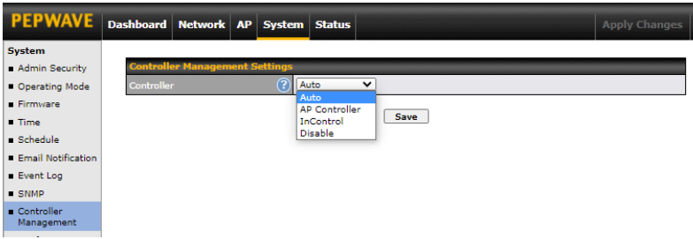
Here is the option to choose the controller management for the access point. This setting specifies via a drop-down menu one of the following valid authentication protocols:
- Auto – AP automatically assigned to active AP Controller.
- AP Controller – AP is controlled by Peplink Balance with AP controller feature.
| AP Controller | |
| Persistent Controller | Check the box Persistent Controller and enter the IP address of the Peplink Balance under Controller Host. |
- InControl – AP is controlled by InControl*
| InControl | |
| Restricted to Status Reporting Only | When the box Restricted to Status Reporting Only is ticked, the AP will only report its status, but can’t be managed or configured by InControl. |
| Privately Host InControl | Check the box “Privately Host InControl” and enter the IP Address or hostname of your InControl Appliance. |
- Disable – You can disable the controller feature on the AP.
*InControl is a cloud-based service which allows you to manage all of your Peplink and Pepwave devices with one unified system. With it, you can generate reports, gather statistics, and configure your devices automatically.
You can sign up for an InControl account at https://incontrol2.peplink.com. You can register your devices under the account, monitor their status, see their usage reports, and receive offline notifications.
Configuration#
Backing up your Pepwave access point settings immediately after successful completion of the initial setup is strongly recommended. The functionality to download and upload Pepwave access point settings is found at System > Configuration.

| Configuration | |
| Restore Configuration to Factory Settings | The Restore Factory Settings button is to reset the configuration to factory default settings. After clicking the button, you will need to click the Apply Changes button on the top right corner to make the settings effective. |
| Download Active Configurations | Click Download to backup the current active settings. |
| Upload Configurations | To restore or change settings based on a configuration file, click Choose File to locate the configuration file on the local computer, and then click Upload. The new settings can then be applied by clicking the Apply Changes button on the page header, or you can cancel the procedure by pressing discard on the main page of the web admin interface. |
LED#
*Please note that the following settings are available only for AP One AX devices.
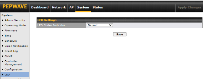
You can control the LED Status Indicator (available only for AP One AX devices). Available options are:
- Default
- Always Turn Off
Feature Add-Ons#
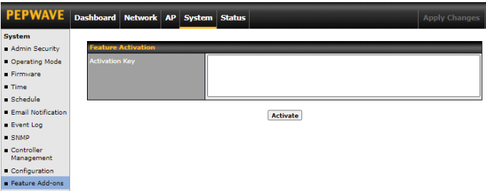
Some Pepwave access point models have features that can be activated upon purchase. Once the purchase is complete, you will receive an activation key. Enter the activation key into the Activation Key field, click Activate, and then click Apply Changes.
Reboot#
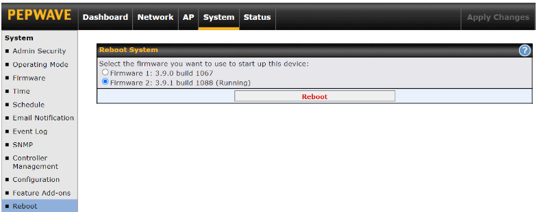
Restart the access point with the Reboot button. For maximum reliability, the Pepwave access point can contain two copies of firmware; each copy can be a different version. You can select the firmware version you would like to reboot the device with. The firmware marked with (Running) is the current system boot up firmware.
Please note that a firmware upgrade will always replace the inactive firmware partition.
Tools#
PING#
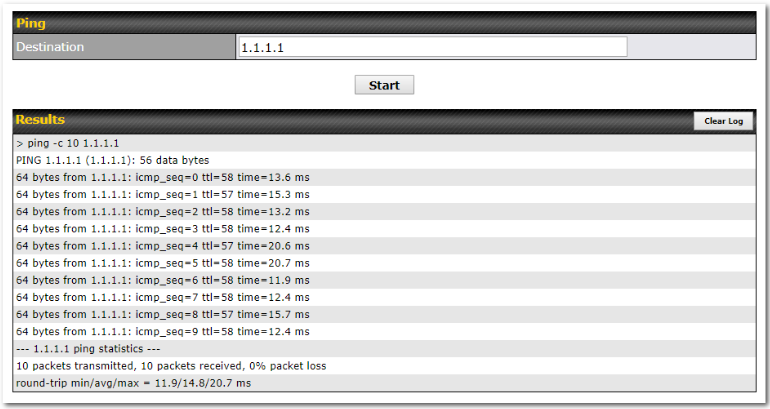
The ping test tool tests connectivity by pinging the specified destination IP address. The ping utility is located at System > Tools > Ping.
Traceroute#

The traceroute test tool traces the routing path to the specified IP address. The traceroute test utility is located at System > Tools > Traceroute.
Wake-on-LAN#
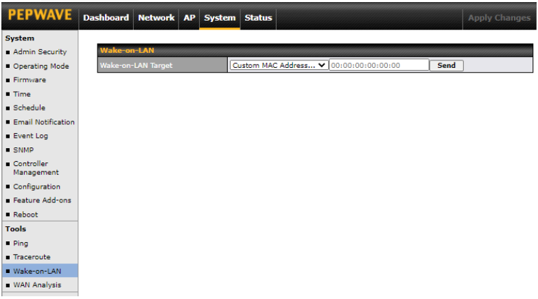
Pepwave access points can send Magic Packets to any client specified from the Web UI. To access this feature, navigate to System > Tools > Wake-on-LAN.
Select a client from the drop-down list and click Send to send a Magic Packet.
WAN Analysis#

The WAN Analysis feature allows you to run a WAN to WAN speed test between two Peplink devices. You may set up a device as either a server or a client. However, one device must be set up as a server to run the speed tests, and the server must have a public IP address.
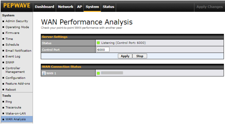
The default Control Port is 6000 and it can be customized if required. The IP address of the WAN interface will be shown in the WAN Connection Status section.
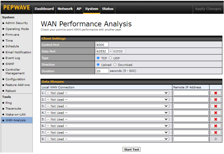
The client side has a few more settings that can be changed. Make sure that the Control Port matches what is entered on the server side. Select the WAN(s) that will be used for testing and enter the server’s WAN IP address(es). Once all of the options have been set, click the Start Test button.
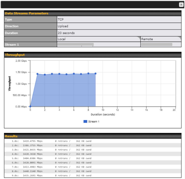
The test output will show the Data Streams Parameters, the Throughput as a graph, and the Results.
The test can be run again once it is complete by clicking the Start button or you can click Close and change the parameters for the test.
Ch9. Status Tab#
The displays available on the Status tab help you monitor device data, client activity, event log, and more.
Device#
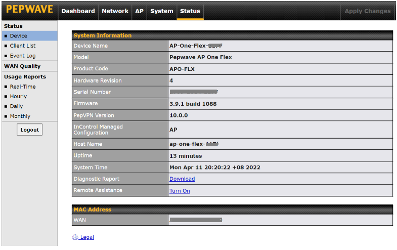
| System Information | |
| Device Name | This is the name specified in the Device Name field located at System > Admin Security. |
| Model | This displays the model of the device. |
| Hardware Revision | This displays the hardware version of this device. |
| Serial Number | This displays the serial number of this device. |
| Firmware | This displays the firmware version this device is currently running. |
| PepVPN Version | This displays the current PepVPN version. |
| Host name | This displays the hostname of the device. |
| Uptime | This displays the length of time since the device has been rebooted. |
| System Time | This displays the current system time. |
| Diagnostic Report | The Download link is for exporting a diagnostic report file required for system investigation. |
| Remote Assistance | Click Turn On to enable remote assistance. |
The second table shows the MAC address of each connected LAN/WAN interface. To view your device’s End User License Agreement (EULA), follow the Legal link.
| Important Note |
| If you encounter issues and would like to contact the Peplink Support Team (https://contact.peplink.com/secure/create-support-ticket.html), please download the diagnostic report file and attach it along with a description of your issue. |
Active Session#
Information on active sessions can be found at Status > Active Sessions > Overview.
*Please note that the following active session will be available only when your access point is operating in Router Mode.

This screen displays the number of sessions initiated by each application. Click on each service listing for additional information. This screen also indicates the number of sessions initiated by each WAN port. In addition, you can see which clients are initiating the most sessions.
You can also perform a filtered search for specific sessions. You can filter by subnet, port, protocol, and interface. To perform a search, navigate to Status > Active Sessions > Search.
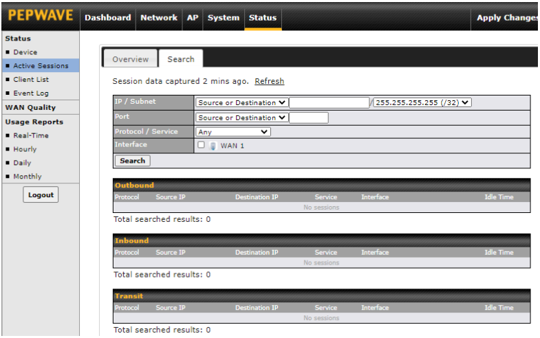
This Active Sessions section displays the active inbound/outbound sessions of each WAN connection on the Pepwave router. A filter is available to sort active session information. Enter a keyword in the field or check the box of one of the WAN connections to filter your search.
Client List#
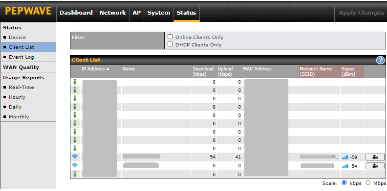
The Client List displays all currently connected clients. It lists DHCP and online client IP addresses, names (retrieved from the DHCP reservation table or defined by users), current download and upload rate, and MAC address.
![]()
In the client list table, there is a Ban Client feature which can be used to disconnect Wi-Fi clients by clicking the ![]() button on the right.
button on the right.

There is a blocklist on the same page after you have banned Wi-Fi clients.

You may also unblock Wi-Fi clients when the client devices need to reconnect to the network by clicking the ![]() button on the right.
button on the right.
Event Log#
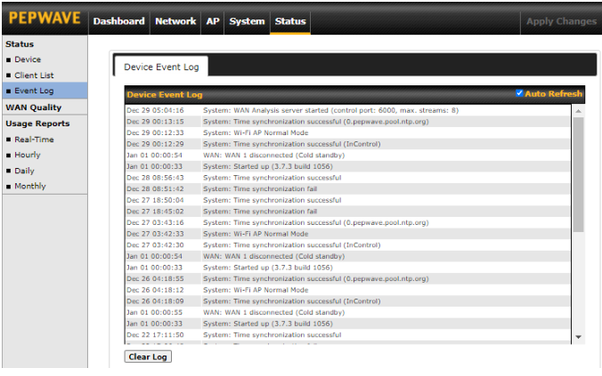
The Event Log displays a list of all events associated with your access point. Check Auto Refresh to refresh log entries automatically. Click the Clear Log button to clear the log.
WAN Quality#
The Status > WAN Quality allows you to select each WAN and view current WAN quality. Detailed information can be seen when selecting a point on the graph.

Usage Reports#
Real-Time#
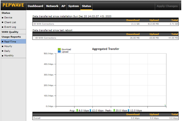
The Data transferred since installation table indicates how much network traffic has been processed by the device since the first bootup. The Data transferred since last reboot table indicates how much network traffic has been processed by the device since the last boot up.
Hourly#
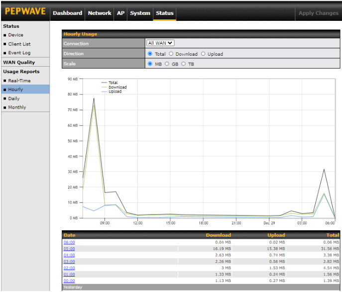
This page shows the hourly bandwidth usage for all WAN connections. Individual connections may be viewed by selecting the desired connection from the drop-down menu.
Daily#
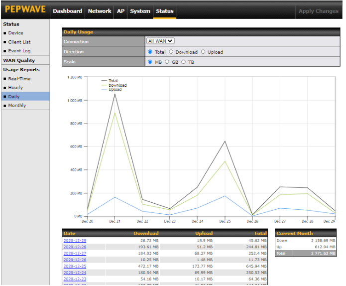
This page shows the daily bandwidth usage for all WAN connections. Individual connections may be viewed by selecting the connection from the drop-down menu. You can check the Current Billing Cycle table for that WAN connection to be displayed. Click on a date to view the client bandwidth usage of that specific date. The scale of the graph can be set to display megabytes (MB), gigabytes (GB), or terabytes (TB).
Monthly#
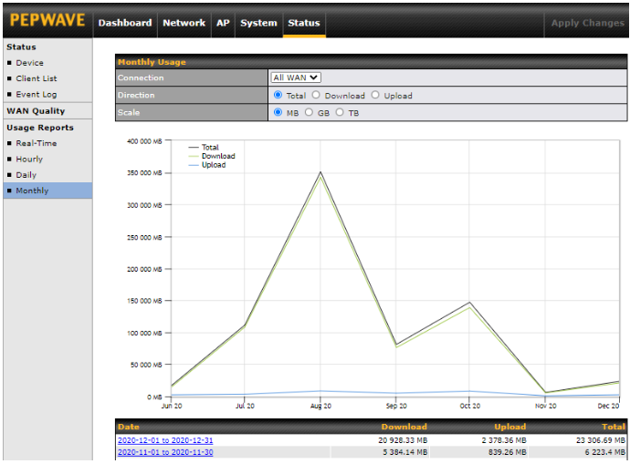
This page shows the monthly bandwidth usage for each WAN connection. You can check the usage of each particular connection and view the information by Billing Cycle or by Calendar Month. Select the first two rows to view the client bandwidth usage for the last two months. The scale of the graph can be set to display megabytes (MB), gigabytes (GB), or terabytes (TB).
Ch10. Restoring Factory Defaults#
To restore the factory default settings on a Pepwave AP One router, follow the steps below:
- Locate the reset button on the front or back panel of the Pepwave AP One router.
- With a paperclip, press and keep the reset button pressed.
Note: There is a dual function to the reset button.
Hold for 5 seconds for admin password reset (Note: The LED status light blinks in RED 2 times and release the button, green status light starts blinking)
Hold for 5 seconds for factory reset (Note: The LED status light blinks in RED 3 times and release the button, all WAN/LAN port lights start blinking)
After the Pepwave AP One router finishes rebooting, the factory default settings will be restored.
| Important Note |
| All previous configurations and bandwidth usage data will be lost after restoring factory default settings. Regular backup of configuration settings is strongly recommended. |
Appendix List#
Ethernet Cables
We recommend that you use a shielded cable to connect the Ethernet ports for the network.
AP One AX Lite & AP One AX#
Federal Communication Commission Interference Statement (AP One AX Lite)
This equipment has been tested and found to comply with the limits for a Class B digital device, pursuant to Part 15 of the FCC Rules. These limits are designed to provide reasonable protection against harmful interference in a residential installation. This equipment generates, uses and can radiate radio frequency energy and, if not installed and used in accordance with the instructions, may cause harmful interference to radio communications. However, there is no guarantee that interference will not occur in a particular installation. If this equipment does cause harmful interference to radio or television reception, which can be determined by turning the equipment off and on, the user is encouraged to try to correct the interference by one of the following measures:
-Reorient or relocate the receiving antenna.
-Increase the separation between the equipment and receiver.
-Connect the equipment into an outlet on a circuit different from that to which the receiver is connected.
-Consult the dealer or an experienced radio/TV technician for help.
Any changes or modifications not expressly approved by the party responsible for compliance could void the user’s authority to operate this equipment.
Radiation Exposure Statement
This equipment complies with FCC radiation exposure limits set forth for an uncontrolled environment. This equipment should be installed and operated with minimum distance 20cm between the radiator & your body.
Industry Canada Statement (AP One AX Lite)
This product meets the applicable Innovation, Science and Economic Development Canada technical specifications.
Le present produit est conforme aux specifications techniques applicables d’Innovation, Sciences et Developpement economique Canada.
This device contains licence-exempt transmitter(s)/receiver(s) that comply with Innovation, Science and Economic Development Canada’s licence-exempt RSS(s). Operation is subject to the following two conditions:
(1) This device may not cause interference.
(2) This device must accept any interference, including interference that may cause undesired operation of the device.
Le present appareil est conforme aux CNR d’Industrie Canada applicables aux appareils radio exempts de licence. L’exploitation est autorisee aux deux conditions suivantes:
(1) l’appareil ne doit pas produire de brouillage, et
(2) l’utilisateur de l’appareil doit accepter tout brouillage radioelectrique subi, meme si le brouillage est susceptible d’en
(i) The device for operation in the band 5150-5250 MHz is only for indoor use to reduce the potential for harmful interference to co-channel mobile satellite systems;
(ii) For devices with detachable antenna(s), the maximum antenna gain permitted for devices in the band 5725-5850 MHz shall be such that the equipment still complies with the e.i.r.p. limits specified for point-to-point and non-point-to-point operation as appropriate; and
The high-power radars are allocated as primary users (i.e. priority users) of the band
5725-5850 MHz and that these radars could cause interference and/or damage to LE-LAN devices.
(i) Le dispositif fonctionnant dans la bande 5150-5250 MHz est reserve uniquement pour une utilisation a l’interieur afin de reduire les risques de brouillage prejudiciable aux systemes de satellites mobiles utilisant les memes canaux;
(ii) Le gain maximal d’antenne permis pour les dispositifs avec antenne(s) amovible(s) utilisant la bande 5725-5850 MHz doit se conformer a la limitation P.I.R.E specifiee pour l’exploitation point a point et non point a point, selon le cas.
En outre, les utilisateurs devraient aussi etre avises que les utilisateurs de radars de haute puissance sont designes utilisateurs principaux (c.-a-d., qu’ils ont la priorite) pour les bande 5725-5850 MHz et que ces radars pourraient causer du brouillage et/ou des dommages aux dispositifs LAN-EL.
Radiation Exposure Statement
This device complies with the ISED radiation exposure limit set forth for an uncontrolled environment. This device should be installed and operated with minimum distance 20cm between the radiator & your body.
Cet equipement est conforme avec l’exposition aux radiations ISED definies pour un environnement non contr6le. Cet equipement doit etre installe et utilise a une distance minimum de 20 cm entre le radiateur et votre corps.
Federal Communication Commission Interference Statement (AP One AX)
This equipment has been tested and found to comply with the limits for a Class B digital device, pursuant to Part 15 of the FCC Rules. These limits are designed to provide reasonable protection against harmful interference in a residential installation. This equipment generates, uses and can radiate radio frequency energy and, if not installed and used in accordance with the instructions, may cause harmful interference to radio communications.
However, there is no guarantee that interference will not occur in a particular installation. If this equipment does cause harmful interference to radio or television reception, which can be determined by turning the equipment off and on, the user is encouraged to try to correct the interference by one of the following measures:
-Reorient or relocate the receiving antenna.
-Increase the separation between the equipment and receiver.
-Connect the equipment into an outlet on a circuit different from that to which the receiver is connected.
-Consult the dealer or an experienced radio/TV technician for help.
Any changes or modifications not expressly approved by the party responsible for compliance could void the user’s authority to operate this equipment.
Radiation Exposure Statement
This equipment complies with FCC radiation exposure limits set forth for an uncontrolled environment. This equipment should be installed and operated with minimum distance 20cm between the radiator & your body.
CE Statement for Peplink Routers ( AP One AX Lite )


2.4GHz ( 2412 – 2472 MHz ) : 19.74 dBm
5GHz ( 5150 – 5250 MHz ) : 22.94 dBm
This equipment complies with CE radiation exposure limits set forth for an uncontrolled envi- ronment. This equipment should be installed and operated with a minimum distance of 20cm between the radiator & your body.
This equipment is restricted to indoor use only when operating in the 5150 to 5250 MHz frequency range in above countries.
contact as: https://www.peplink.com
UK Statement for Peplink Routers ( AP One AX Lite )
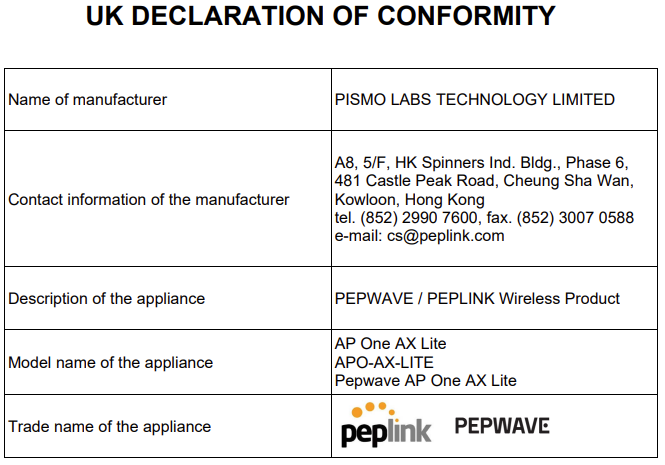
CE Statement for Peplink Routers ( AP One AX )


2.4GHz ( 2412 – 2472 MHz ) : 19.87 dBm
5GHz ( 5150 – 5250 MHz ) : 22.78 dBm
This equipment complies with CE radiation exposure limits set forth for an uncontrolled envi- ronment. This equipment should be installed and operated with a minimum distance of 20cm between the radiator & your body.
This equipment is restricted to indoor use only when operating in the 5150 to 5250 MHz frequency range in above countries.
contact as: https://www.peplink.com/
UK Statement for Peplink Routers ( AP One AX )

AP One AC Mini#
Federal Communication Commission Interference Statement ( AP One AC Mini)
This equipment has been tested and found to comply with the limits for a Class B digital device, pursuant to part 15 of the FCC Rules. These limits are designed to provide reasonable protection against harmful interference in a residential installation. This equipment generates, uses and can radiate radio frequency energy and, if not installed and used in accordance with the instructions, may cause harmful interference to radio communications. However, there is no guarantee that interference will not occur in a particular installation. If this equipment does cause harmful interference to radio or television reception, which can be determined by turning the equipment off and on, the user is encouraged to try to correct the interference by one or more of the following measures:
-Reorient or relocate the receiving antenna.
-Increase the separation between the equipment and receiver.
-Connect the equipment into an outlet on a circuit different from that to which the receiver is connected.
-Consult the dealer or an experienced radio/TV technician for help.
Any changes or modifications not expressly approved by the party responsible for compliance could void the user’s authority to operate this equipment.
Radiation Exposure Statement
This equipment complies with FCC radiation exposure limits set forth for an uncontrolled environment. This equipment should be installed and operated with minimum distance 20cm between the radiator & your body.
Industry Canada Statement ( AP One AC Mini)
This product meets the applicable Innovation, Science and Economic Development Canada technical specifications.
Le present produit est conforme aux specifications techniques applicables d’Innovation, Sciences et Developpement economique Canada.
This device contains licence-exempt transmitter(s)/receiver(s) that comply with Innovation, Science and Economic Development Canada’s licence-exempt RSS(s). Operation is subject to the following two conditions:
(1) This device may not cause interference.
(2) This device must accept any interference, including interference that may cause undesired operation of the device.
Le present appareil est conforme aux CNR d’Industrie Canada applicables aux appareils radio exempts de licence. L’exploitation est autorisee aux deux conditions suivantes:
(1) l’appareil ne doit pas produire de brouillage, et
(2) l’utilisateur de l’appareil doit accepter tout brouillage radioelectrique subi, meme si le brouillage est susceptible d’en
(i) The device for operation in the band 5150-5250 MHz is only for indoor use to reduce the potential for harmful interference to co-channel mobile satellite systems;
(ii) For devices with detachable antenna(s), the maximum antenna gain permitted for devices in the band 5725-5850 MHz shall be such that the equipment still complies with the e.i.r.p. limits specified for point-to-point and non-point-to-point operation as appropriate; and
The high-power radars are allocated as primary users (i.e. priority users) of the band 5725-5850 MHz and that these radars could cause interference and/or damage to LE- LAN devices.
(i) Le dispositif fonctionnant dans la bande 5150-5250 MHz est reserve uniquement pour une utilisation a l’interieur afin de reduire les risques de brouillage prejudiciable aux systemes de satellites mobiles utilisant les memes canaux;
(ii) Le gain maximal d’antenne permis pour les dispositifs avec antenne(s) amovible(s) utilisant la bande 5725-5850 MHz doit se conformer a la limitation P.I.R.E specifiee pour l’exploitation point a point et non point a point, selon le cas.
En outre, les utilisateurs devraient aussi etre avises que les utilisateurs de radars de haute puissance sont designes utilisateurs principaux (c.-a-d., qu’ils ont la priorite) pour les bande 5725-5850 MHz et que ces radars pourraient causer du brouillage et/ou des dommages aux dispositifs LAN-EL.
Radiation Exposure Statement
This device complies with the ISED radiation exposure limit set forth for an uncontrolled environment. This device should be installed and operated with minimum distance 20cm between the radiator & your body.
Cet equipement est conforme avec l’exposition aux radiations ISED definies pour un environnement non contr6le. Cet equipement doit etre installe et utilise a une distance minimum de 20 cm entre le radiateur et votre corps.
CE Statement for Peplink Routers ( AP One AC Mini )

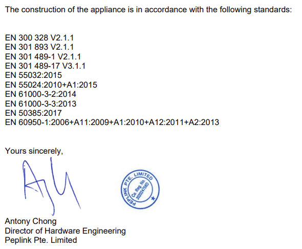

2.4GHz ( 2412 – 2472 MHz ) : 19.89 dBm
5GHz ( 5150 – 5250 MHz ) : 22.70 dBm
This equipment complies with CE radiation exposure limits set forth for an uncontrolled envi- ronment. This equipment should be installed and operated with a minimum distance of 2cm between the radiator & your body.
This equipment is restricted to indoor use only when operating in the 5150 to 5250 MHz frequency range in above countries.
contact as: https://www.peplink.com
AP One Rugged HW2#
FCC Requirements for Operation in the United States
Federal Communications Commission (FCC) Compliance Notice:
For AP One Rugged HW2 (FCC ID: U8G-P1MT01)
Federal Communication Commission Interference Statement
Any changes or modifications not expressly approved by the party responsible for compliance could void your authority to operate the equipment.
This equipment has been tested and found to comply with the limits for a Class A digital device, pursuant to part 15 of the FCC Rules. These limits are designed to provide reasonable protection against harmful interference when the equipment is operated in a commercial environment. This equipment generates, uses, and can radiate radio frequency energy and, if not installed and used in accordance with the instruction manual, it may cause harmful interference to radio communications. Operation of this equipment in a residential area is likely to cause harmful interference, in which case the user will be required to correct the interference at his own expense.
This device complies with Part 15 of the FCC Rules. Operation is subject to the following two conditions:
(1) this device may not cause harmful interference and
(2) this device must accept any interference received, including interference that may cause undesired operation.
Radiation Exposure Statement
This equipment complies with FCC RF radiation exposure limits set forth for an uncontrolled
environment. This equipment should be installed and operated with a minimum distance of 20 cm between the radiator and your body.
VCCI Class A Statement
この装置は、クラスA機器です。この装置を住宅環境で使用すると電波妨害を引き起こすことがあります。この場合には使用者が適切な対策を講ずるよう要求されることがあります。
VCCI-A
CE Statement for Peplink Routers ( AP One Rugged HW2 )
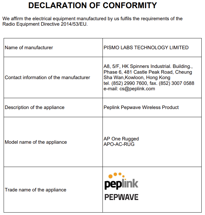
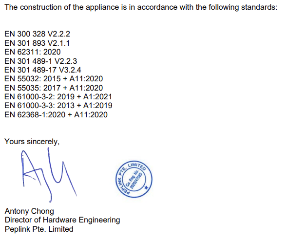

2.4GHz ( 2412 – 2472 MHz ) : 19.95 dBm
5GHz ( 5150 – 5250 MHz ) : 22.65 dBm
This equipment complies with CE radiation exposure limits set forth for an uncontrolled envi- ronment. This equipment should be installed and operated with a minimum distance of 20cm between the radiator & your body.
This equipment is restricted to indoor use only when operating in the 5150 to 5250 MHz frequency range in above countries.
contact as: https://www.peplink.com/
UK Statement for Peplink Routers ( AP One Rugged HW2 )


AP Pro AX#
Federal Communication Commission Interference Statement (AP Pro AX)
This equipment has been tested and found to comply with the limits for a Class A digital device, pursuant to part 15 of the FCC Rules. These limits are designed to provide reasonable protection against harmful interference when the equipment is operated in a commercial environment. This equipment generates, uses, and can radiate radio frequency energy and, if not installed and used in accordance with the instruction manual, it may cause harmful interference to radio communications. Operation of this equipment in a residential area is likely to cause harmful interference, in which case the user will be required to correct the interference at his own expense.
-This device complies with Part 15 of the FCC Rules. Operation is subject to the following
two conditions:
(1) this device may not cause harmful interference and
(2) this device must accept any interference received, including interference that may cause undesired operation.
Any changes or modifications not expressly approved by the party responsible for compliance could void the user’s authority to operate this equipment.
Radiation Exposure Statement
This equipment complies with FCC radiation exposure limits set forth for an uncontrolled environment. This equipment should be installed and operated with minimum distance 20cm between the radiator & your body.
Professional Installation Instruction
This product is designed for specific application and needs to be installed by qualified personnel who has RF and related rule knowledge and need to get the Peplink certified to install the product. The general user shall not attempt to install or change the settings.
Innovation, Science and Economic Development Canada Statement ( AP Pro AX )
This product meets the applicable Innovation, Science and Economic Development Canada technical specifications.
Le present produit est conforme aux specifications techniques applicables d’Innovation, Sciences et Developpement economique Canada.
This device contains licence-exempt transmitter(s)/receiver(s) that comply with Innovation, Science and Economic Development Canada’s licence-exempt RSS(s). Operation is subject to the following two conditions:
(1) This device may not cause interference.
(2) This device must accept any interference, including interference that may cause undesired operation of the device.
Le present appareil est conforme aux CNR d’Industrie Canada applicables aux appareils radio exempts de licence. L’exploitation est autorisee aux deux conditions suivantes:
(1) l’appareil ne doit pas produire de brouillage, et
(2) l’utilisateur de l’appareil doit accepter tout brouillage radioelectrique subi, meme si le brouillage est susceptible d’en
(i) The device for operation in the band 5150-5250 MHz is only for indoor use to reduce the potential for harmful interference to co-channel mobile satellite systems;
(ii) For devices with detachable antenna(s), the maximum antenna gain permitted for devices in the band 5725-5850 MHz shall be such that the equipment still complies with the e.i.r.p. limits specified for point-to-point and non-point-to-point operation as appropriate; and
The high-power radars are allocated as primary users (i.e. priority users) of the band 5725-5850 MHz and that these radars could cause interference and/or damage to LE- LAN devices.
(i) Le dispositif fonctionnant dans la bande 5150-5250 MHz est reserve uniquement pour une utilisation a l’interieur afin de reduire les risques de brouillage prejudiciable aux systemes de satellites mobiles utilisant les memes canaux;
(ii) Le gain maximal d’antenne permis pour les dispositifs avec antenne(s) amovible(s) utilisant la bande 5725-5850 MHz doit se conformer a la limitation P.I.R.E specifiee pour l’exploitation point a point et non point a point, selon le cas.
En outre, les utilisateurs devraient aussi etre avises que les utilisateurs de radars de haute puissance sont designes utilisateurs principaux (c.-a-d., qu’ils ont la priorite) pour les bande 5725-5850 MHz et que ces radars pourraient causer du brouillage et/ou des dommages aux dispositifs LAN-EL.
Radiation Exposure Statement
This device complies with the ISED radiation exposure limit set forth for an uncontrolled environment. This device should be installed and operated with minimum distance 20cm between the radiator & your body.
Cet equipement est conforme avec l’exposition aux radiations ISED definies pour un environnement non contr6le. Cet equipement doit etre installe et utilise a une distance minimum de 20 cm entre le radiateur et votre corps.
CE Statement for Peplink Routers ( AP Pro AX )

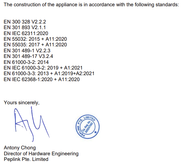

2.4GHz ( 2412 – 2472 MHz ) : 19.86 dBm
5GHz ( 5470 – 5725 MHz ) : 29.66 dBm
This equipment complies with CE radiation exposure limits set forth for an uncontrolled envi- ronment. This equipment should be installed and operated with a minimum distance of 20cm between the radiator & your body.
This equipment is restricted to indoor use only when operating in the 5150 to 5250 MHz frequency range in above countries.
contact as: https://www.peplink.com/
UK Statement for Peplink Routers ( AP Pro AX )

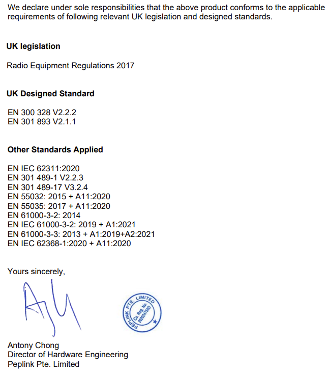
AP One Mini#
FCC Requirements for Operation in the United States
Federal Communications Commission (FCC) Compliance Notice:
For AP One Mini
Federal Communication Commission Interference Statement
Any changes or modifications not expressly approved by the party responsible for compliance could void your authority to operate the equipment.
This equipment has been tested and found to comply with the limits for a Class B digital device,
pursuant to part 15 of the FCC Rules. These limits are designed to provide reasonable
protection against harmful interference in a residential installation. This equipment generates,
uses and can radiate radio frequency energy and, if not installed and used in accordance with
the instructions, may cause harmful interference to radio communications. However, there is no
guarantee that interference will not occur in a particular installation. If this equipment does
cause harmful interference to radio or television reception, which can be determined by turning
the equipment off and on, the user is encouraged to try to correct the interference by one or
more of the following measures:
—Reorient or relocate the receiving antenna.
—Increase the separation between the equipment and receiver.
—Connect the equipment into an outlet on a circuit different from that to which the receiver is
connected.
—Consult the dealer or an experienced radio/TV technician for help.
This device complies with Part 15 of the FCC Rules. Operation is subject to the following two conditions:
(1) this device may not cause harmful interference and
(2) this device must accept any interference received, including interference that may cause undesired operation.
Radiation Exposure Statement
This equipment complies with FCC RF radiation exposure limits set forth for an uncontrolled
environment. This equipment should be installed and operated with a minimum distance of 20 cm between the radiator and your body.
Industry Canada Statement (AP One Mini)
This product meets the applicable Innovation, Science and Economic Development Canada
technical specifications.
Le présent produit est conforme aux spécifications techniques applicables d’Innovation,
Sciences et Développement économique Canada.
This device contains licence-exempt transmitter(s)/receiver(s) that comply with Innovation,
Science and Economic Development Canada’s licence-exempt RSS(s). Operation is subject to
the following two conditions:
(1) This device may not cause interference.
(2) This device must accept any interference, including interference that may cause undesired
operation of the device.
Le present appareil est conforme aux CNR d’Industrie Canada applicables aux appareils radio
ex-empts de licence. L’exploitation est autorisee aux deux conditions suivantes:
(1) l’appareil ne doit pas produire de brouillage, et
(2) l’utilisateur de l’appareil doit accepter tout brouillage radioelectrique subi, meme si le
brouillage est susceptible d’en
(i) The device for operation in the band 5150–5250 MHz is only for indoor use to reduce the
potent for harmful interference to co-channel mobile satellite systems;
(ii) For devices with detachable antenna(s), the maximum antenna gain permitted for devices
in the band 5725-5850 MHz shall be such that the equipment still complies with the e.i.r.p.
limits as appropriate; (detachable antenna only) ; and
The high-power radars are allocated as primary users (i.e. priority users) of the band 5725-5850
MHz and that these radars could cause interference and/or damage to LE-LAN devices.
(iii) For devices with detachable antenna(s), the maximum antenna gain permitted for devices in
the band 5725-5850 MHz shall be such that the equipment still complies with the e.i.r.p. limits
specified for point-to-point and non-point-to-point operation as appropriate.
(i) Le dispositif fonctionnant dans la bande 5150-5250 MHz est réservé uniquement pour une
utilisation à l’intérieur afin de réduire les risques de brouillage préjudiciable aux systèmes de
satellites mobiles utilisant les mêmes canaux;
(ii) Le gain maximal d’antenne permis pour les dispositifs avec antenne(s) amovible(s) utilisant
la bande 5725-5850 MHz doit se conformer à la limitation P.I.R.E spécifiée pour l’exploitation
point à point et non point à point, selon le cas.
En outre, les utilisateurs devraient aussi être avisés que les utilisateurs de radars de haute
puissance sont désignés utilisateurs principaux (c.-à-d., qu’ils ont la priorité) pour les bandes
5725-5850 MHz et que ces radars pourraient causer du brouillage et/ou des dommages aux
dispositifs LAN-EL.
(iii) Le gain maximal d’antenne permis pour les dispositifs avec antenne(s) amovible(s) utilisant
la bande 5725-5850 MHz doit se conformer à la limitation P.I.R.E spécifiée pour l’exploitation
point à point et non point à point.
Radiation Exposure Statement
This equipment complies with ISED RF radiation exposure limits set forth for an uncontrolled
environment. This equipment should be installed and operated with a minimum distance of 20
cm between the radiator and your body.
Cet appareil doit être installé et utilisé avec une distance minimale de 20cm entre l’émetteuret
votre corps. Cet appareil et sa ou ses antennes ne doivent pas être co-localisés ou fonctionner
en conjonction avec tout autre antenne ou transmetteur.
This radio transmitter IC: 20682-P1MT12 has been approved by Innovation, Science and
Economic Development Canada to operate with the antenna types listed below, with the
maximum permissible gain indicated. Antenna types not included in this list that have a gain
greater than the maximum gain indicated for any type listed are strictly prohibited for use with
this device.
WIFI Antenna type: PIFA
WIFI Antenna gain: 2.4GHz / 3.3 dBi
5150 ~ 5250 MHz / 3.3dBi
5725 ~ 5850 MHz / 3.9 dBi
Cet émetteur radio IC : 20682-P1MT12 a été approuvé par Innovation, Sciences et
Développement économique Canada pour fonctionner avec les types d’antennes répertoriés cidessous, avec le gain maximal autorisé indiqué. Les types d’antenne non inclus dans cette liste qui ont un gain supérieur au gain maximum indiqué pour tout type répertorié sont strictement interdits pour une utilisation avec cet appareil.
Type d’antenne WIFI : PIFA
Gain de l’antenne Wi-Fi : 2.4 GHz / 3.3 dBi
5150 ~ 5250 MHz / 3.3 dBi
5725 ~ 5850 MHz / 3.9 dBi
NCC Statement
取得審驗證明之低功率射頻器材,非經核准,公司、商號或使用者均不得擅自變更頻率、加大功率或變更原設計之特性及功能。 低功率射頻器材之使用不得影響飛航安全及干擾合法通信;經發現有干擾現象時,應立即停用, 並改善至無干擾時方得繼續使用。 前述合法通信,指依電信管理法規定作業之無線電通信。 低功率射頻器材須忍受合法通信或工業、科學及醫療用電波輻射性電機設備之干擾。
應避免影響附近雷達系統之操作。
BSMI Declaration of the Presence Condition of the Restricted Substances Marking

UK PSTI Statement of Compliance#
For AP One Mini

For AP Pro AX
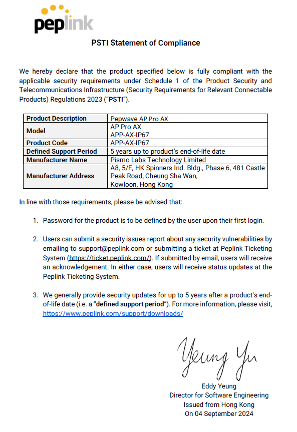
For AP One AX
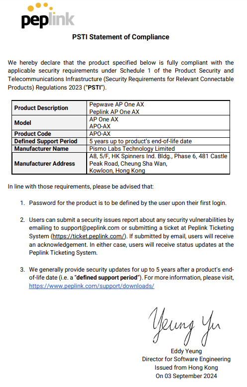
For AP One AX Lite
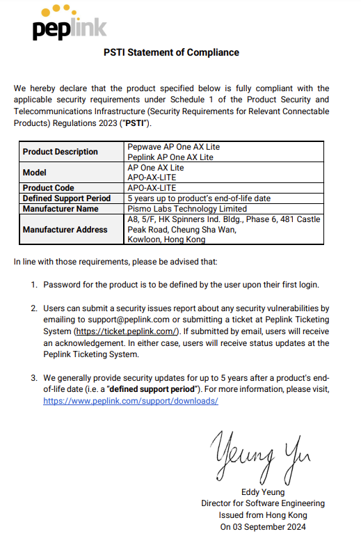
For AP One Rugged

EU Cybersecurity Declaration of Conformity#
For AP One Mini

For AP Pro AX

For AP One AX

For AP One AX Lite
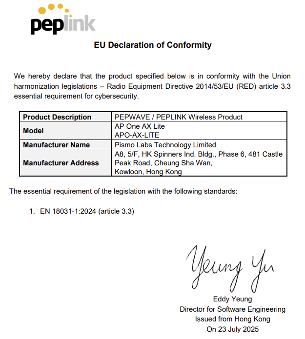
For AP One Rugged
