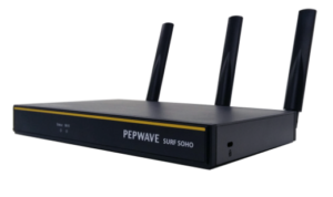
Peplink Surf SOHO
User Manual
Peplink Products:
Surf SOHO
Peplink Firmware 8.3.0
June 2025

Peplink Surf SOHO
User Manual
Peplink Products:
Surf SOHO
Peplink Firmware 8.3.0
June 2025
The Surf SOHO is a professional-grade router that is secure, reliable, and easy to use.
With the Surf SOHO, you can connect to the Internet using a USB cellular modem, Ethernet, or Wi-Fi. Hook the Surf SOHO up to Ethernet and Cellular connections, and it will automatically fail over from one to the other as needed. That way, you can stay connected even when a connection breaks
This manual covers setting up a Surf SOHO router and provides an introduction to their features and usage.
Tips

Want to know more about Pepwave routers? Visit our YouTube Channel for a video introduction.
The following terms, acronyms, and abbreviations are frequently used in this manual:
|
Term |
Definition |
|
3G |
3rd generation standards for wireless communications (e.g., HSDPA) |
|
4G |
4th generation standards for wireless communications (e.g., LTE) |
|
DHCP |
Dynamic Host Configuration Protocol |
|
DNS |
Domain Name System |
|
EVDO |
Evolution-Data Optimized |
|
FQDN |
Fully Qualified Domain Name |
|
HSDPA |
High-Speed Downlink Packet Access |
|
HTTP |
Hyper-Text Transfer Protocol |
|
ICMP |
Internet Control Message Protocol |
|
IP |
Internet Protocol |
|
LAN |
Local Area Network |
|
MAC Address |
Media Access Control Address |
|
MTU |
Maximum Transmission Unit |
|
MSS |
Maximum Segment Size |
|
NAT |
Network Address Translation |
|
PPPoE |
Point to Point Protocol over Ethernet |
|
QoS |
Quality of Service |
|
SNMP |
Simple Network Management Protocol |
|
TCP |
Transmission Control Protocol |
|
UDP |
User Datagram Protocol |
|
VPN |
Virtual Private Network |
|
VRRP |
Virtual Router Redundancy Protocol |
|
WAN |
Wide Area Network |
|
WINS |
Windows Internet Name Service |
|
WLAN |
Wireless Local Area Network |
Pepwave Surf SOHO routers enable all LAN users to share broadband Internet connections, and they provide advanced features to enhance Internet access. Our Surf SOHO routers support one Ethernet, one USB 4G LTE/3G WAN, and Wi-Fi as WAN for failover
It also includes three SMA dual-band antennas that allows better reliability, larger bandwidth, and increased wireless coverage. Below is a list of supported features on Pepwave routers. Features vary by model.
For more information, please visit our website.
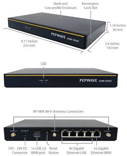
| Specifications | |
| WAN Interface | 1x 100/1000M Ethernet Port 1x USB 2.0 Interface Wi-Fi as WAN |
| LAN Interface | 4x 100/1000M Ethernet Ports Simultaneous Dual-Band 11ac Wi-Fi AP |
| Wi-Fi AP Operating Frequency | 2412 – 2472 MHz and 5180 – 5825 MHz |
| Wi-Fi Antenna | 3x External Wi-Fi Antenna |
| Recommended Users | 1-25 |
| Router Throughput | 120Mbps |
| Number of PPTP VPN Users | 3 |
| Number of PPTP VPN Users | 2 |
| Power Input | DC Jack: 10V − 24VDC
AC Adapter: AC Input 100V − 240V, DC Output 12V, 1.5A |
| Power Consumption | 26W (max) with USB WAN
22W (max) without USB WAN |
| Dimensions | 9.17 x 5.6 x 1.18 inch
233 x 142 x 30 mm |
| Weight | 0.86 pounds
388 grams |
| Operating Temperature | -14° to 113°F
-10° to 45°C |
| Humidity | 15% – 95% (non-condensing) |
| Certifications | FCC, CE, RoHS |
| Warranty | 1-Year Limited Warranty |
The statuses indicated by the front panel LEDs are as follows:
|
Wi-Fi and Status Indicators |
||
|
Wi-Fi |
OFF |
Disabled Intermittent |
|
Blinking |
Enabled but no client connected |
|
|
ON |
Client(s) connected to wireless network |
|
|
Continuous blinking |
Transferring data to wireless network |
|
|
Status |
OFF |
System initializing |
|
Red |
Booting up or busy |
|
|
Green |
Ready state |
|
|
LAN and Ethernet WAN Ports |
||
Green LED |
ON |
1000 Mbps |
|
OFF |
10 Mbps / 100 Mbps or port is not connected |
|
Orange LED |
ON |
Port is being connected |
|
Blinking |
Data is being transferred |
|
|
OFF |
No data is being transferred or port is not connected |
|
|
Port type |
Auto MDI/MDI-X ports |
|
|
Wi-Fi Signal |
|
|
Off |
No connection |
|
Signal strength |
Wi-Fi signal strength (low, medium, and high) |

As your organization grows, it may require more bandwidth, but modifying your network can be tedious. In Drop-in Mode, you can conveniently install your Peplink router without making any changes to your network. For any reason your Peplink router looses power, the LAN Bypass will safely and automatically bypass the Peplink router to resume your original network connection.

VoIP and videoconferencing are highly sensitive to latency. With QoS, Peplink routers can detect VoIP traffic and assign it the highest priority, giving you crystal-clear calls.
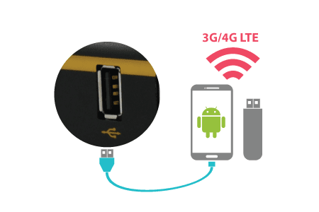
For increased WAN diversity, plug in a USB LTE modem as a backup. Peplink routers are compatible with over 250 modem types.

Use OpenVPN or L2TP with IPsec to safely and conveniently connect remote clients to your private network. L2TP with IPsec is supported by most devices, but legacy devices can also connect using PPTP.
Click here for the full instructions on setting up L2TP with IPsec.
Click here for the full instructions on setting up OpenVPN connections
The DPI report written in the updated KB article will show further information on InControl2 through breaking down application categories into subcategories.
sscs
Pepwave routers support Wi-Fi “Air Monitoring Mode” which used to troubleshoot remotely and proactively monitor Wi-Fi and WAN performance. The report can be viewed under InControl 2 > Reports > AirProbe Reports after enabling Wi-Fi Air Monitoring.
Note: To enable this feature, go to https://<Device’s IP>/cgi-bin/MANGA/support.cgi
![]()
The SP Default Configuration feature written in the updated KB article allows for the provisioning of custom made settings (a.k.a. InControl2 configuration) via the Ethernet LAN port and is ideal for those wanting to do a bulk deployment of many Peplink devices.
Note: If you would like to use this feature, please contact your purchase point (Eg.VAD).
Cloud Service Providers often restrict access to certain applications. With SFC Relay, you can route traffic before going out to the Internet, allowing access to previously restricted applications experienced with the public SpeedFusion Cloud nodes. Available as an add-on for your home router or as an upgradable license to your Peplink router, SFC Relay is sure to impress you and any peers you give access to.
DoH provides the benefits of communicating DNS information over a secure HTTPS connection in an encrypted manner. The protocol offers increased privacy and confidentiality by preventing data interception and man-in-the-middle attacks.
InTouch is Peplink’s zero-touch remote network management solution, leveraging InControl 2 and a SpeedFusion Connect (formerly known as SpeedFusion Cloud) data plan. This service extends a network administrator’s ability to reach any device UI backed by a Peplink/Pepwave router. To configure InTouch, all you need is a valid InControl 2 subscription, a SpeedFusion Connect data plan, and a Peplink/Pepwave router (which requires the latest 8.2.0 firmware).
To watch a demonstration and read the FAQ, visit https://www.peplink.com/enterprise-solutions/intouch/
Or learn to configure InTouch at https://youtu.be/zg0iavHGkJw
The following section details connecting Pepwave routers to your network.
Before installing your Pepwave router, please prepare the following as appropriate for your installation:
A computer with the TCP/IP network protocol and a web browser installed. Supported browsers include Microsoft Internet Explorer 11 or above, Mozilla Firefox 24 or above, Apple Safari 7 or above, and Google Chrome 18 or above.
Construct the network according to the following steps:
1: With an Ethernet cable, connect a computer to one of the LAN ports on the Pepwave router. Repeat with different cables for up to 4 computers to be connected.
2: With another Ethernet cable or a USB modem/Wi-Fi antenna/, connect to one of the WAN ports on the Pepwave router. Repeat the same procedure for other WAN ports.
Connect the power adapter to the power connector on the rear panel of the Pepwave router, and then plug it into a power outlet.
Start a web browser on a computer that is connected with the Pepwave Surf SOHO through the LAN.
To connect to the web admin of the Pepwave Surf SOHO, enter the following LAN IP address in the address field of the web browser: https://192.168.50.1
(This is the default LAN IP address of the Pepwave Surf SOHO.) Enter the following to access the web admin interface.)
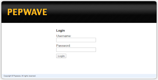
Username: admin
Password: admin
(This is the default admin user login of the Pepwave Surf SOHO.)
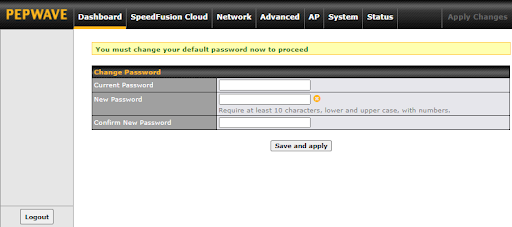
You must change the default password on the first successful logon.
Password requirements are: A minimum of 10 lower AND upper case characters, including at least 1 number.
When HTTP is selected, the URL will be redirected to HTTPS by default.
After successful login, the Dashboard of the web admin interface will be displayed.
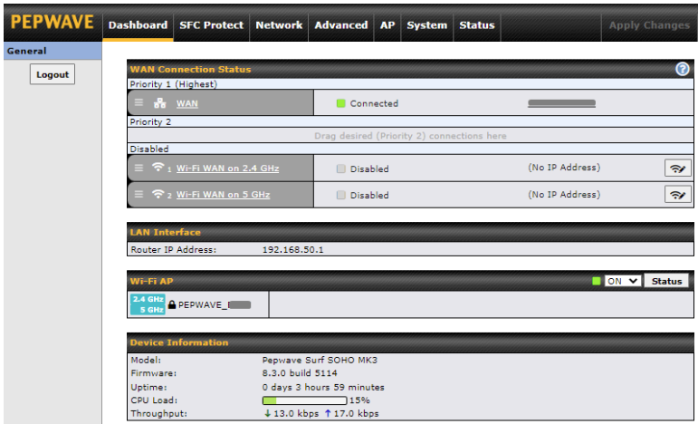
The Dashboard shows current WAN, LAN, and Wi-Fi AP statuses. Here, you can change WAN connection priority and switch on/off the Wi-Fi AP.
Device Information displays details about the device, including model name, firmware version,CPU Load, throughput and uptime..
|
Important Note |
|
Configuration changes (e.g. WAN, LAN, admin settings, etc.) will take effect only after clicking the Save button at the bottom of each page. The Apply Changes button causes the changes to be saved and applied. |
With Peplink products, your device is able to connect to SpeedFusion Cloud without the use of a second endpoint. This service has wide access to a number of SpeedFusion endpoints hosted from around the world, providing your device with unbreakable connectivity wherever you are.*

*SpeedFusion Connect Protect is supported in firmware version 8.1.0 and above. SpeedFusion Connect Protect is a subscription basis. SpeedFusion Connect Protect license can be purchased at https://estore.peplink.com/ > SpeedFusion Service > SpeedFusion Connect Protect.
All Care plans now come with SpeedFusion Connect Protect included. This data allowance will automatically begin and end in accordance with your warranty. No activation is required.
Access the Web Admin of the device you want to create as the Peplink Relay Server, navigating to the “AFC Protect” tab.
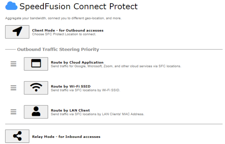
To set up a Peplink Relay Server, select “Relay Mode – for Inbound accesses” > Choose the SFC Protect Location you wish to connect to > Click on the green tick button to confirm the change.

The Relay Sharing Code will be generated and other peers can use this code to establish a SpeedFusion Connect connection that will forward the traffic to this device, allowing them to access local networks and the Internet via your WAN connection.

To connect to SpeedFusion Connect Protect, you can select a SFC Protect Location of your choice, or simply Automatic, then the device will establish a connection to the nearest cloud server.
Choose Automatic > Click on the green tick button to confirm the change.

Or you may select Home Sharing and use your Relay Sharing Code to create a profile if you have set up a Peplink Relay Client on another device.

Click on Apply Changes to save the change.

By default, the router will build a SpeedFusion tunnel to the SpeedFusion Cloud.

If you are running a latency sensitive service like video streaming or VOIP, a WAN Smoothing sub-tunnel can be created. Navigate to SFC Protect > Client Mode – for Outbound accesses > SFC.

A SpeedFusion tunnel configuration window will pop out. Click on the + sign to create the WAN Smoothing sub-tunnel.
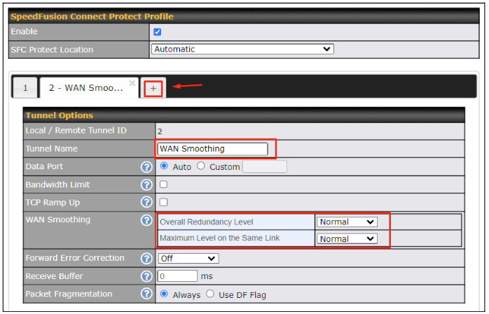
Click on Save and Apply Changes to save the configuration. Now, the router has 2 SpeedFusion tunnels to the SpeedFusion Cloud.

Create an outbound policy to steer the internet traffic to go into SFC Protect. Please go to Advanced > Outbound Policy, click on Add Rule to create a new outbound policy.
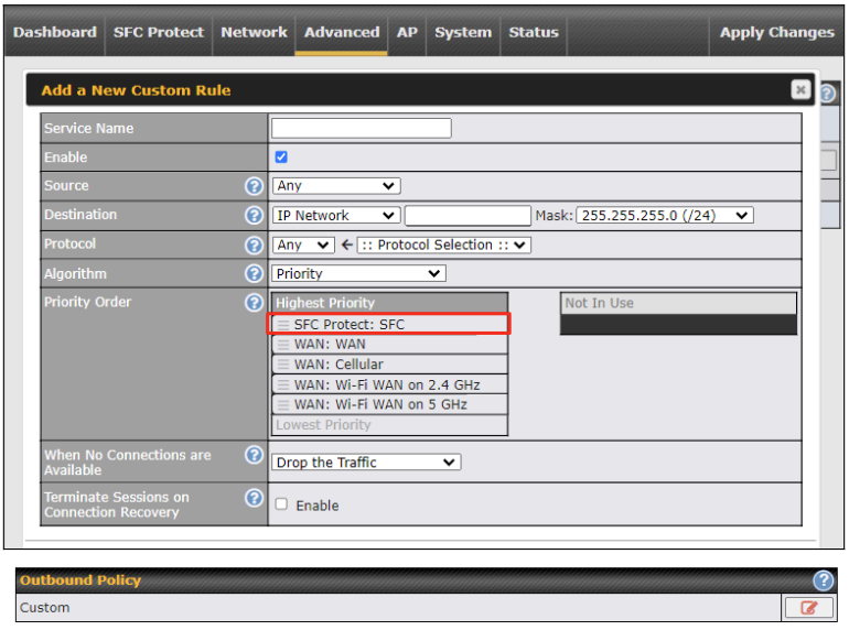
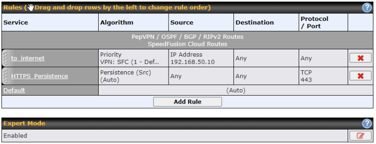
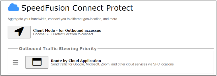
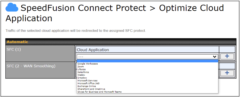
Optimize Cloud Application allows you to route Internet traffic to SpeedFusion Connect Protect based on the application. Go to SFC Protect > Route by Cloud Application.
Select a Cloud application to route through SpeedFusion Cloud from the drop down list > Click ![]() > Save > Apply Changes. Click the
> Save > Apply Changes. Click the ![]() to remove a selected Cloud application to route through SpeedFusion Cloud.
to remove a selected Cloud application to route through SpeedFusion Cloud.
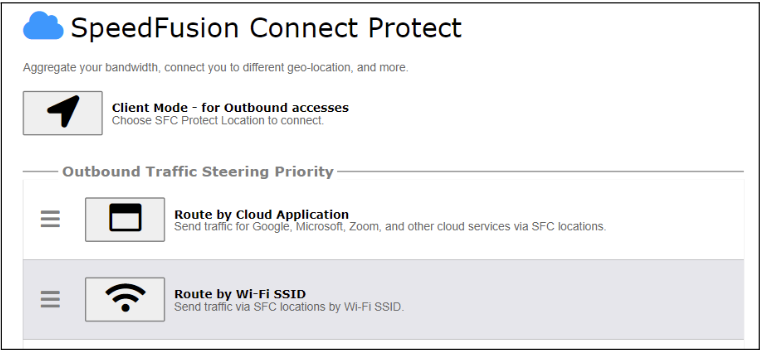
SpeedFusion Connect Protect provides a convenient way to route the Wi-Fi client to the cloud from SFC Protect > Route by Wi-Fi SSID.
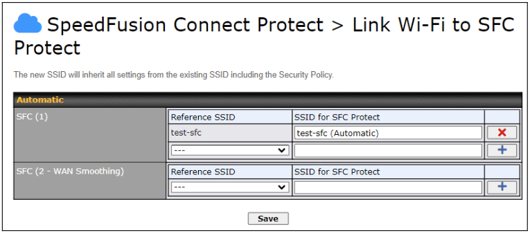
Create a new SSID for SFC Protect. The new SSID will inherit all settings from one of the existing SSIDs including the Security Policy. Then click Save followed by Apply Changes.
SFC Protect SSID will be shown on Dashboard.

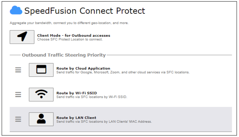
SpeedFusion Connect Protectt provides a convenient way to route the LAN client to the cloud from SFC Protect > Route by LAN Client.
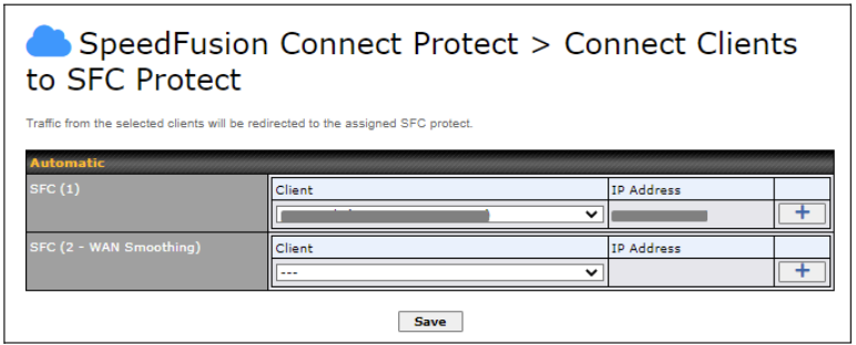
Choose a client from the drop down list > Click + > Save > Apply Changes.
LAN interface settings are located at Network > LAN > Network Settings. Navigating to that page will show the following dashboard:

This represents the LAN interfaces that are active on your router (including VLAN). A gray “X” means that the VLAN is used in other settings and cannot be deleted.
You can find which settings are using the VLAN by hovering over the gray “X”.
Alternatively, a red “X” means that there are no settings using the VLAN.
You can delete that VLAN by clicking the red “X”
Clicking any of the existing LAN interfaces (or creating a new one) will show the following:

|
IP Settings |
|
|
IP Address |
The IP address and subnet mask of the Pepwave router on the LAN. |

|
Network Settings |
|
|
Name |
Enter a name for the LAN. |
|
VLAN ID |
Enter a number for your VLAN. |
|
Inter-VLAN routing |
Check this box to enable routing between virtual LANs. |

|
Layer 2 SpeedFusion VPN Bridging |
|
|
SpeedFusion VPN Profiles to Bridge |
The remote network of the selected PepVPN profiles will be bridged with this local LAN, creating a Layer 2 PepVPN, they will be connected and operate like a single LAN, and any broadcast or multicast packets will be sent over the VPN. |
|
Spanning Tree Protocol |
Click the box will enable STP for this layer 2 profile bridge. |
|
DHCP Option 82 Injection |
Click on the question Mark if you want to enable DHCP Option 82. This allows the device to inject Option 82 with Router Name information before forwarding the DHCP Request packet to a PepVPN peer, such that the DHCP Server can identify where the request originates from. |
|
Override IP Address when bridge connected |
Select “Do not override” if the LAN IP address and local DHCP server should remain unchanged after the Layer 2 PepVPN is up. If you choose to override IP address when the VPN is connected, the device will not act as a router, and most Layer 3 routing functions will cease to work. |
|
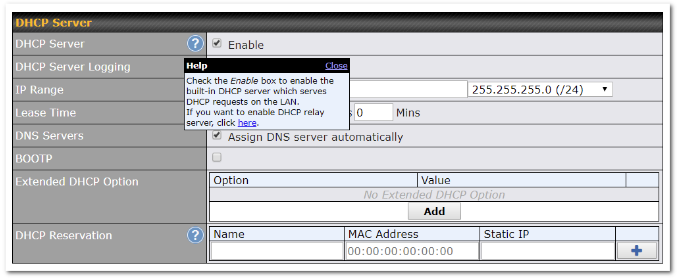
DHCP Server Settings |
|
|
DHCP Server |
When this setting is enabled, the DHCP server automatically assigns an IP address to each computer that is connected via LAN and configured to obtain an IP address via DHCP. The Pepwave router’s DHCP server can prevent IP address collision on the LAN. |
|
DHCP Server Logging |
Enable logging of DHCP events in the eventlog by selecting the checkbox. |
|
IP Range & Subnet Mask |
These settings allocate a range of IP addresses that will be assigned to LAN computers by the Pepwave router’s DHCP server. |
|
Lease Time |
This setting specifies the length of time throughout which an IP address of a DHCP client remains valid. Upon expiration of the lease time, the assigned IP address will no longer be valid and renewal of the IP address assignment will be required. |
|
DNS Servers |
This option allows you to input the DNS server addresses to be offered to DHCP clients. If Assign DNS server automatically is selected, the Pepwave router’s built-in DNS server address (i.e., LAN IP address) will be offered. |
|
BOOTP |
Check this box to enable BOOTP on older networks that still require it. |
|
Extended DHCP Option |
In addition to standard DHCP options (e.g., DNS server address, gateway address, subnet mask), you can specify the value of additional extended DHCP options, as defined in RFC 2132. With these extended options enabled, you can pass additional configuration information to LAN hosts. To define an extended DHCP option, click the Add button, choose the option to define and enter its value. For values that are in IP address list format, you can enter one IP address per line in the provided text area input control. Each option can be defined once only. |
|
DHCP Reservation |
This setting reserves the assignment of fixed IP addresses for a list of computers on the LAN. The computers to be assigned fixed IP addresses on the LAN are identified by their MAC addresses. The fixed IP address assignment is displayed as a cross-reference list between the computers’ names, MAC addresses, and fixed IP addresses. Name (an optional field) allows you to specify a name to represent the device. MAC addresses should be in the format of 00:AA:BB:CC:DD:EE. Press |

|
DHCP Relay Settings |
|
|
DHCP Relay |
Enter the address of the DHCP server here. DHCP requests will be relayed to it. |
|
DHCP Server IP Address |
DHCP requests from the LAN are relayed to the entered DHCP server. For active-passive DHCP server configurations, enter active and passive DHCP server IPs into the DHCP Server 1 and DHCP Server 2 fields. |
|
DHCP Option 82 |
This feature includes device information as relay agent for the attached client when forwarding DHCP requests from a DHCP client to a DHCP server. Device MAC address and network name are embedded to circuit ID and Remote ID in option 82. |
|
DHCP Relay Logging |
Check this box to log DHCP relay activity. |
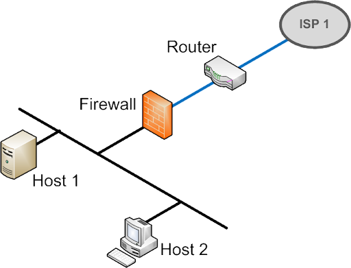
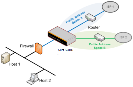
Drop-in mode (or transparent bridging mode) eases the installation of the Surf SOHO on a live network between the firewall and router, such that changes to the settings of existing equipment are not required.
The following diagram illustrates drop-in mode setup:
Check the box Enable to enable the Drop-in Mode. After enabling this feature and selecting the WAN for Drop-in mode, various settings including the WAN’s connection method and IP address will be automatically updated.
When drop-in mode is enabled, the LAN and the WAN for drop-in mode ports will be bridged. Traffic between the LAN hosts and WAN router will be forwarded between the devices. In this case, the hosts on both sides will not notice any IP or MAC address changes.
After successfully setting up the Surf SOHO as part of the network using drop-in mode, it will, depending on model, support one or more WAN connections. Some SOHO units also support multiple WAN connections after activating drop-in mode, though a SpeedFusion license may be required to activate more than one WAN port.
Please note the Drop-In Mode is mutually exclusive with VLAN.
|
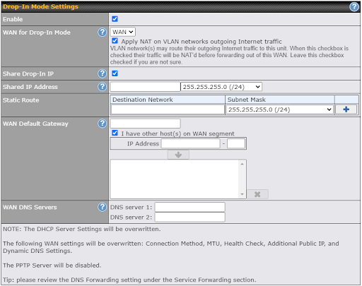
Drop-in Mode Settings |
|
|
Enable |
Drop-in mode eases the installation of the Surf SOHO on a live network between the existing firewall and router, such that no configuration changes are required on existing equipment. Check the box to enable the drop-in mode feature. |
|
WAN for Drop-In Mode |
Select the WAN port to be used for drop-in mode. If WAN is selected, the high availability feature will be disabled automatically. |
|
Shared Drop-In IP* |
When this option is enabled, the passthrough IP address will be used to connect to WAN hosts (email notification, remote syslog, etc.). The SOHO will listen for this IP address when WAN hosts access services provided by the SOHO (web admin access from the WAN, DNS server requests, etc.). To connect to hosts on the LAN (email notification, remote syslog, etc.), the default gateway address will be used. The SOHO will listen for this IP address when LAN hosts access services provided by the SOHO(web admin access from the WAN, DNS proxy, etc.). |
|
Shared IP Address* |
Access to this IP address will be passed through to the LAN port if this device is not serving the service being accessed. The shared IP address will be used in connecting to hosts on the WAN (e.g., email notification, remote syslog, etc.) The device will also listen on the IP address when hosts on the WAN access services served on this device (e.g., web admin accesses from WAN, DNS server, etc.) |
|
WAN Default Gateway |
Enter the WAN router’s IP address in this field. If there are more hosts in addition to the router on the WAN segment, click the |
|
WAN DNS Servers |
Enter the selected WAN’s corresponding DNS server IP addresses. |
* – Advanced feature, please click the ![]() button on the top right-hand corner to activate.
button on the top right-hand corner to activate.

|
Static Route Settings |
|
|
Static Route |
This table is for defining static routing rules for the LAN segment. A static route consists of the network address, subnet mask, and gateway address. The address and subnet mask values are in w.x.y.z format. The local LAN subnet and subnets behind the LAN will be advertised to the VPN. Remote routes sent over the VPN will also be accepted. Any VPN member will be able to route to the local subnets. Press Entries in this list will allow traffic to route to a different subnet that is connected to the LAN interface. Any traffic destined for a network/mask pair will be directed to the corresponding gateway instead of routed through WANs. |

n case of a network address conflict with remote peers (i.e. PepVPN / IPsec VPN / IP Forwarding WAN are considered as remote connections), you can define Virtual Network Mapping to resolve it.
Note: OSPF & RIPv2 settings should be updated as well to avoid advertising conflicted network.
For further details on virtual network mapping watch this video: https://youtu.be/C1FMdZCn3Z8
|
Virtual Network Mapping |
|
|
One-to-One NAT |
Every IP Address in the Local Network has a corresponding unique Virtual IP Address for NAT. |
|
Many-to-One NAT |
The subnet range defined in Local Network will be mapped to a single Virtual IP Address for NAT. Traffic can only be initiated from local to remote, and these traffic will be NAT’ed and behaves like coming from the same Virtual IP Address. |
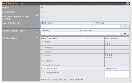
|
DNS Proxy Settings |
|
|
Enable |
To enable the DNS proxy feature, check this box, and then set up the feature at Network>LAN>DNS Proxy Settings. A DNS proxy server can be enabled to serve DNS requests originating from LAN/PPTP/SpeedFusionTM peers. Requests are forwarded to the DNS servers/resolvers defined for each WAN connection. |
|
DNS Caching |
This field is to enable DNS caching on the built-in DNS proxy server. When the option is enabled, queried DNS replies will be cached until the records’ TTL has been reached. This feature can improve DNS response time by storing all received DNS results for faster DNS lookup. However, it cannot return the most updated result for frequently updated DNS records. By default, DNS Caching is disabled. |
|
Include Google Public DNS Servers |
When this option is enabled, the DNS proxy server will forward DNS requests to Google’s public DNS servers, in addition to the DNS servers defined in each WAN. This could increase the DNS service’s availability. This setting is disabled by default. |
|
Local DNS Records |
This table is for defining custom local DNS records. A static local DNS record consists of a host name and IP address. When looking up the host name from the LAN to LAN IP of the Pepwave Surf SOHO, the corresponding IP address will be returned. To display the option to set TTL manually, click |
|
Domain Lookup Policy* |
DNS proxy will look up the domain names defined here using only the specified connections. |
|
DNS Resolvers* |
Check the box to enable the WINS server. A list of WINS clients will be displayed at Network>LAN>DNS Proxy Settings>DNS Resolvers. This field specifies which DNS resolvers will receive forwarded DNS requests. If no WAN/VPN/LAN DNS resolver is selected, all of the WAN’s DNS resolvers will be selected. |
* – Advanced feature, please click the ![]() button on the top right-hand corner to activate.
button on the top right-hand corner to activate.
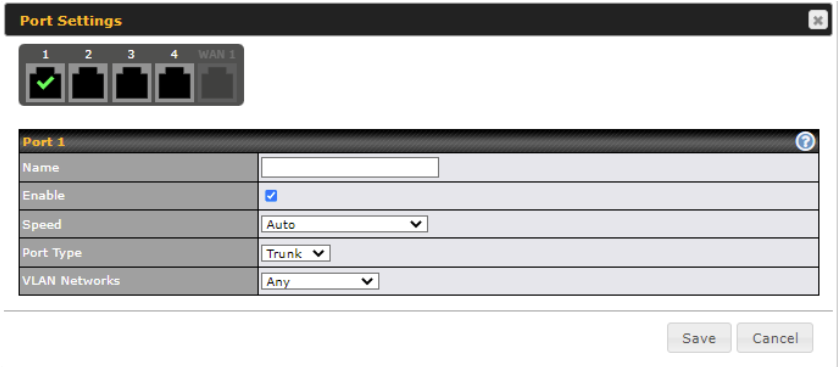
Click ![]() to configure port settings, navigate to Network > LAN > Port Settings
to configure port settings, navigate to Network > LAN > Port Settings

On this screen, you can enable specific ports, name the LAN ports, as well as determine the speed of the LAN ports.
| Port Settings | |
| Name | Enter a name for the LAN port. |
| Enable | Tick to enable or disable the specific port. |
| Speed | This is the port speed of the LAN interface. It should be set to the same speed as the connected device to avoid port negotiation problems. When a static speed is set, you may choose whether to advertise its speed to the peer device. Auto is selected by default. You can choose not to advertise the port speed if the port has difficulty negotiating with the peer device. |
| Port Type | This field is to configure the port type to Trunk or Access for the LAN port. |
| VLAN Networks | Assign a VLAN to a LAN port. |
WAN Interface settings are located at Network > WAN.
The router supports wan connections supplied by a USB 2.0 Interface USB cellular modem, Ethernet, or Wi-Fi.
To reorder the WAN priority, drag on the appropriate WAN by holding the left mouse button, move it to the desired priority (the first one would be the highest priority, the second one would be lower priority, and so on), and drop it by releasing the mouse button.
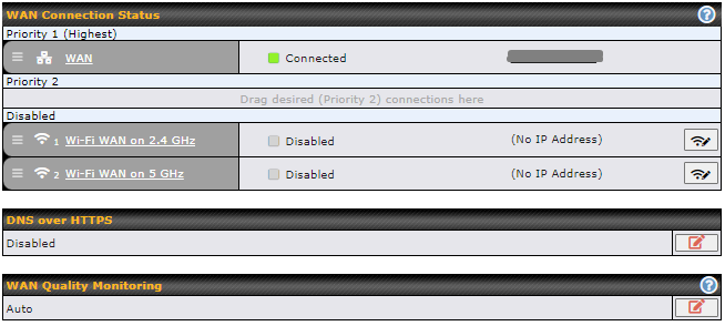
To disable a particular WAN connection, drag on the appropriate WAN by holding the left mouse button, move it the Disabled row, and drop it by releasing the mouse button.
You can also set priorities on the Dashboard. Click the WAN button in the corresponding row to modify the connection setting.
![]()
You can enable DoH (DNS over HTTPS) support in this section.

|
DNS over HTTPS |
|
|
Enable |
When this option is enabled, the DNS proxy server will use HTTPS connections to forward DNS requests to the DoH resolver; it will not fallback to traditional UDP DNS options. |
|
Server |
The options to configure DoH with a predefined server are:
|
This setting advice how WAN Quality information is being gathered.
By default, WAN Quality information will always be collected automatically for all WAN connections.
With a customized choice of WAN connections, the router will only collect the WAN Quality information of those selected WAN connections.

|
Important Note |
|
Connection details will be changed and become effective immediately after clicking the Save and Apply button. |
WAN connection details need to be configured to connect the router to the internet or another WAN
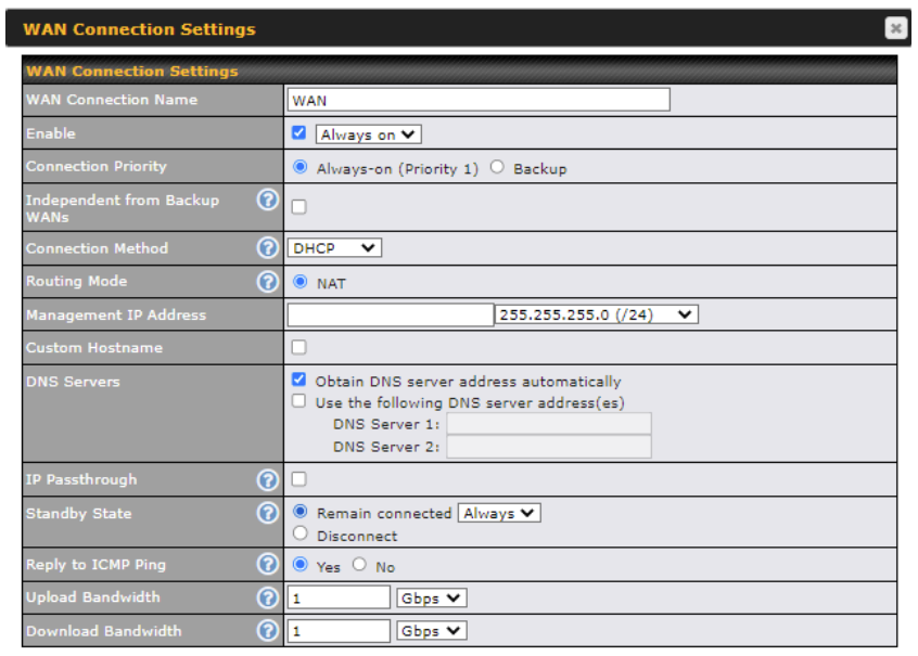
To start configuring the WAN connection choose Network > WAN from the menu and choose a WAN connection and then click it.
|
WAN Connection Settings |
|
|
WAN Connection Name |
Enter a name to represent this WAN connection. |
|
Enable |
This setting enables the WAN connection. If schedules have been defined, you will be able to select a schedule to apply to the connection. |
|
Connection Priority |
This option allows you to configure the WAN connection whether for normal daily usage or as a backup connection only. If Always-on is chosen, the WAN connection will be kept on continuously, regardless of the priority of other WAN connections. If Backup is chosen, the WAN connection will depend on other WAN connections. It will not be used when one or more higher priority dependent WAN connections are connected. |
|
Independent from Backup WANs |
If this is checked, the connection will be working independent from other Backup WAN connections. Those in Backup Priority will ignore the status of this WAN connection, and will be used when none of the other higher priority connections are available |
|
Connection Method |
There are five possible connection methods for Ethernet WAN:
The connection method and details are determined by, and can be obtained from the ISP. |
|
Routing Mode |
This field shows that NAT (network address translation) will be applied to the traffic routed over this WAN connection. IP Forwarding is available when you click the link in the help text. |
|
Management IP Address |
Management IP Address is available for configuration when you click the link in the help This option allows you to configure the management IP address for the DHCP WAN connection. |
|
Custom Hostname |
Provide a hostname for this WAN port if requested by the ISP |
|
DNS Servers |
Select a DNS server for this port to use. This port can either be automatically selected or manually designated. |
|
IP Passthrough |
When this IP Passthrough option is active, after the ethernet WAN connection is up, the router’s DHCP server will offer the connection’s IP address to one LAN client. All incoming or outgoing traffic will be routed without NAT. |
|
Standby State |
This option allows you to choose whether to remain the connection connected or disconnect it when this WAN connection is no longer in the highest priority and has entered the standby state. |
|
Reply to ICMP Ping |
If No is selected, this option is disabled and the system will not reply to any ICMP ping echo requests to the WAN IP addresses of this WAN connection(Default option is “Yes”) |
|
Upload Bandwidth |
This field refers to the maximum upload speed. This value is referenced when default weight is chosen for outbound traffic and traffic prioritization. A correct value can result in effective traffic prioritization and efficient use of upstream bandwidth. |
|
Download Bandwidth |
This field refers to the maximum download speed. Default weight control for outbound traffic will be adjusted according to this value. |

| Physical Interface Settings | |
| Port Speed | This setting specifies port speed and duplex configurations of the WAN port. By default, Auto is selected and the appropriate data speed is automatically detected by the Pepwave router. In the event of negotiation issues, the port speed can be manually specified. You can also choose whether or not to advertise the speed to the peer by selecting the Advertise Speed checkbox. |
| MTU | This setting specifies the maximum transmission unit. By default, MTU is set to Custom 1440. You may adjust the MTU value by editing the text field. Click Default to restore the default MTU value. Select Auto and the appropriate MTU value will be automatically detected. Auto-detection will run each time the WAN connection establishes. |
| MSS | This setting should be configured based on the maximum payload size that the local system can handle. The MSS (maximum segment size) is computed from the MTU minus 40 bytes for TCP over IPv4. If the MTU is set to Auto, the MSS will also be set automatically. By default, MSS is set to Auto. |
| MAC Address Clone | Some service providers (e.g., cable providers) identify the client’s MAC address and require the client to always use the same MAC address to connect to the network. In such cases, change the WAN interface’s MAC address to the original client PC’s MAC address via this field. The default MAC address is a unique value assigned at the factory. In most cases, the default value is sufficient. Clicking Default restores the MAC address to the default value. |
| VLAN | Click the square if you wish to enable VLAN functionality for the WAN connection and enable multiple broadcast domains. Once you enable VLAN, you will be able to enter a name for your network. |
To ensure traffic is routed to healthy WAN connections only, the Pepwave router can periodically check the health of each WAN connection. The health check settings for each WAN connection can be independently configured.

|
Health Check Settings |
|
|
Health Check Method |
This field specifies the Health Check method to be used for this WAN connection. This value can be configured as Disabled, PING, DNS Lookup, or HTTP.
When Disabled is chosen in the method field, the WAN connection will always be considered as up. The connection will NOT be treated as down in the event of IP routing errors.
The router will send an ICMP/PING packet to the specified IP address (or host name) to test WAN connectivity.
The router will perform a DNS lookup to the specified DNS server.
The router will perform an HTTP request to the specified URLs. Optional with strings to match. |
|
Timeout |
During any health check, the router will send a health check packet. The router will wait the specified number of seconds for a response before the health check is considered as failed. |
|
Health Check Interval |
This number specifies the period between each health check. |
|
Health Check Retries |
This number specified the number of health check attempts the router will make. Upon reaching this number, the link will be considered as failed |
|
Recovery Retries |
This specified the number of successful health checks a failed links needs before the link is considered as up again. |
The Bandwidth Allowance Monitor helps to keep track of your network usage.
To enable this function, connect to the Web Admin Interface and go to Network > WAN.
Check the box Enable next to Bandwidth Allowance Monitor and you can see the following:

|
Bandwidth Allowance Monitor |
|
|
Action |
If the feature Email Notification is enabled, you will be notified through email when usage hits 75% and 95% of the monthly allowance. If the box Disconnect when usage hits 100% of monthly allowance is checked, this WAN connection will be disconnected automatically when the usage hits the monthly allowance. It will not resume connection unless this option has been turned off or the usage has been reset when a new billing cycle starts. |
|
Start Day |
This option allows you to define which day in the month each billing cycle begins. |
|
Monthly Allowance |
This field is for defining the maximum bandwidth usage allowed for the WAN connection each month. |
The IP Address list represents the list of fixed Internet IP addresses assigned by the ISP, in the event that more than one Internet IP address is assigned to this WAN connection.
Enter the subnet IP Address and Subnet Mask, press the down arrow button, and the list will be populated by the IP addresses of the specified subnet. You should delete the WAN connection’s primary IP address and the gateway address from the list by pressing the Delete button after selecting them in the list.
These additional IP addresses can be assigned to a device on the LAN using NAT Mappings
Pepwave Surf SOHO routers allow registering domain name relationships to dynamic DNS service providers. Through registration with dynamic DNS service provider(s), the default public Internet IP address of each WAN connection can be associated with a hostname.
With dynamic DNS service enabled for a WAN connection, you can connect to your WAN’s IP address externally even if its IP address is dynamic.
You must register for an account from the listed dynamic DNS service providers before enabling this option.
If the WAN connection’s IP address is a reserved private IP address (i.e., behind a NAT router), the public IP of each WAN will be automatically reported to the DNS service provider.
Either upon a change in IP addresses or every 23 days without link reconnection, the Pepwave Surf SOHO will connect to the dynamic DNS service provider to update the provider’s IP address records.
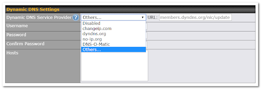
If your desired provider is not listed, you may check with DNS-O-Matic. This service supports updating 30 other dynamic DNS service providers. (Note: Peplink is not affiliated with DNS-O-Matic.)
To access Wi-Fi WAN settings, click Network > WAN > Wireless network connection.
The WiFi-WAN and USB WiFi Network connection configuration is similar to the Ethernet WAN configuration, but has a few unique options that are shown in this section.
The options that are the same as the ethernet WAN connection configuration are shown in the Ethernet WAN section.
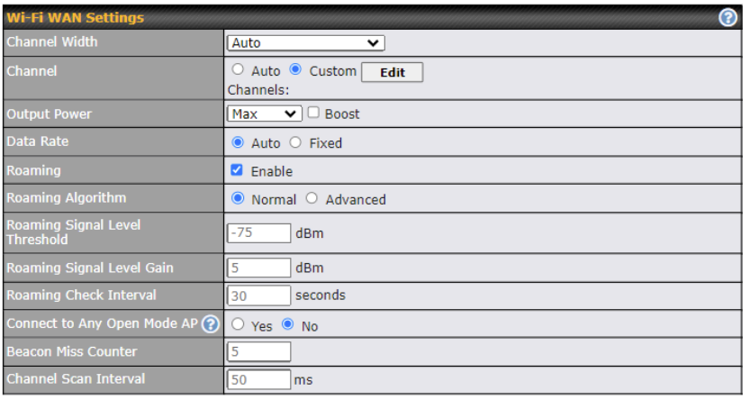
| Wi-Fi WAN Settings | |
| Channel Width | choose between the available options 20 Mhz, 20/40Mhz, 20/40/80 Mhz |
| Channel Selection | Determine whether the channel will be automatically selected. If you select custom, the following table will appear:
|
| Output Power | Low, Medium, High, Max (boost options for tickbox).
Max is the Maximum transmit power supported for that country / Maximum power supported of that device (the smaller value). High, Medium, Low is having -3dBm each from the previous level. Transmit power of 2.4Ghz is generally approximately 20dBm. |
| Data Rate | One of the available advanced options is the ability to configure the Data rate according to the MCS Index (see http://mcsindex.com/) |
| Roaming | Checking this box will enable Wi-Fi roaming.
|
| Roaming Algorithm | select Normal (default) pr Advanced (enables Intensive Scan options) |
| Roaming Signal Level Threshold | Configure the Roaming Signal Level Threshold in dBm |
| Roaming Signal Level Gain | Configure the Roaming Signal Level Gain in dBm |
| Roaming Check Interval | Configure the Roaming Check Interval in Seconds |
| Connect to Any Open Mode AP | This option is to specify whether the Wi-Fi WAN will connect to any open mode access points it finds. |
| Beacon Miss Counter | Client devices will disconnect from the AP when this amount of beacons is missed |
| Channel Scan Interval | Configure Channel Scan Interval in ms. |
You can manually create a profile to connect to a Wi-Fi connection. This is useful for creating a profile for connecting to hidden-SSID access points. Click Network > WAN Connection Name > Create Profile… to get started.
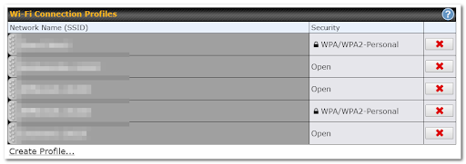
This will open a window similar to the one shown below:
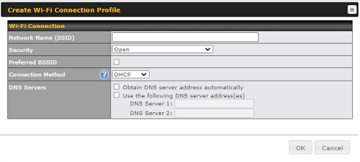
| Wi-Fi Connection Profile Settings | |
| Network Name (SSID) | Enter a name to represent this Wi-Fi connection. |
| Security |
This option allows you to select which security policy is used for this wireless network. Available options: WPA3 – Personal WPA2/WPA3 – Personal 802.1x with dynamic WEP key |
| Preferred BSSID | Configure the BSSID; the BSSID is the MAC address of the wireless access point (WAP) |
| Connection Method | Choose DHCP or Static IP |
| DNS servers | Configure the DNS servers that this WAN connection should use |
If signal threshold is defined, this connection will be treated as down when a weaker than threshold signal is determined.
The signal threshold can also be configured using values (this option can be enabled after selecting the question mark)
Indication of WiFi strength values:
| Signal Strength | Quality indication |
| -30 dBm | Maximum signal strength |
| -50 dBm | Excellent signal strength |
| -60 dBm | Good, reliable signal strength |
| -67 dBm | Minimum signal strength for applications that require very reliable, timely delivery of data packets. |
| -70 dBm | Not strong; goof for soet internet browsing and email |
| -80 dBm | Unreliable |
| -90 dBm | Unusable |
SpeedFusion VPN is the core engine of Peplink site-to-site VPN technology.
It is ideal for establishing a secure tunnel over any WAN link.
On top of all the benefits of IPsec and other conventional VPN technologies, the SpeedFusion VPN engine also offers:
Long-distance Ethernet cable − SpeedFusion VPN allows a secure and seamless Ethernet tunnel over any IP connection (Layer 2 over Layer 3). It virtually provides a long-distance Ethernet cable over any WAN link.
Works in any dynamic IP environment − SpeedFusion VPN is fully compatible with any dynamic IP environment and NAT, allowing you to establish a VPN behind a NAT gateway or firewall without worrying about static IP addresses (one public IP address is needed to establish a PepVPN Connection).
To start, navigate to Network > VPN > SpeedFusion and enter a Local ID and click save.
This device will be identified by other SpeedFusion Peers by this local ID
When a SpeedFusion VPN connection is established between sites, the local LAN subnet and subnets behind the LAN (defined under Static Route on the LAN settings page) will be advertised to the VPN. All VPN members (branch offices and headquarters) will be able to route to local subnets.
Note that all LAN subnets and the subnets behind them must be unique. Otherwise, VPN members will not be able to access each other.
All data can be routed over the VPN using the 256-bit AES encryption standard. Each profile specifies the settings for creating a VPN connection with one remote Pepwave or Peplink device.
The Pepwave Surf Soho supports 2 SpeedFusion VPN remote peers per device (5 with upgrade license).
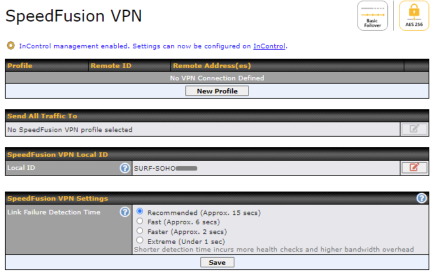
To configure SpeedFusion VPN, navigate to Advanced > SpeedFusion VPN and select New Profile.
The example below had all SpeedFusion VPN advanced features enabled.
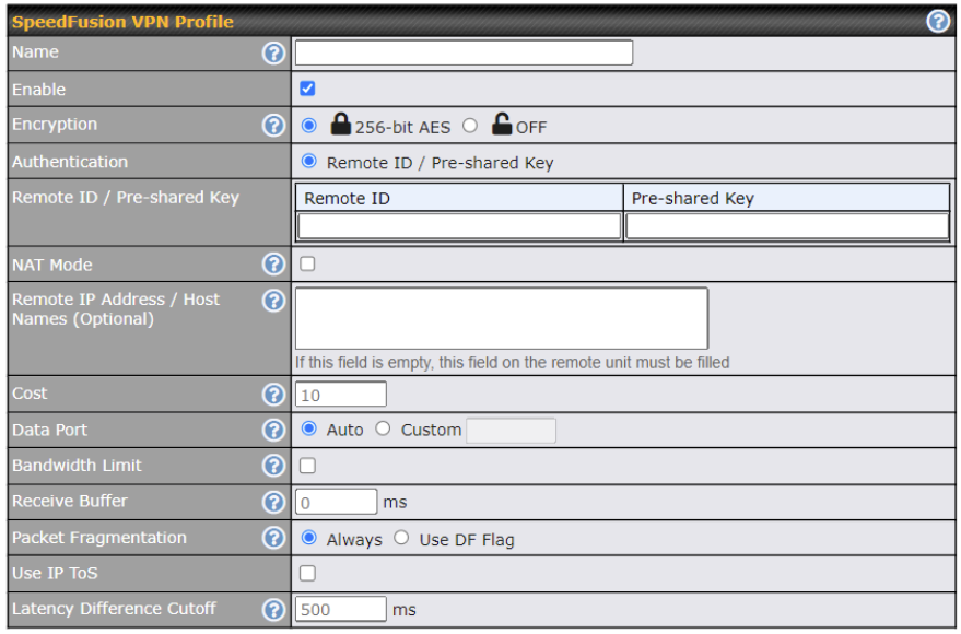
| SpeedFusion VPN Profile Settings | |
| Name | This field is for specifying a name to represent this profile. The name can be any combination of alphanumeric characters (0-9, A-Z, a-z), underscores (_), dashes (-), and/or non-leading/trailing spaces ( ). |
| Enable | When this box is checked, this VPN connection profile will be enabled. Otherwise, it will be disabled. |
| Encryption | By default, VPN traffic is encrypted with 256-bit AES. If Off is selected on both sides of a VPN connection, no encryption will be applied. |
| Authentication | Select from By Remote ID Only, Preshared Key. When selecting By Remote ID Only, be sure to enter a unique peer ID number in the Remote ID field. |
| Remote ID /
Pre-shared Key |
This optional field becomes available when Remote ID / Pre-shared Key is selected as the Pepwave Surf SOHO’s VPN Authentication method, as explained above. Pre-shared Key defines the pre-shared key used for this particular VPN connection. The VPN connection’s session key will be further protected by the pre-shared key. The connection will be up only if the pre-shared keys on each side match. When the peer is running firmware 5.0+, this setting will be ignored. |
| NAT Mode | Check this box to allow the local DHCP server to assign an IP address to the remote peer. When NAT Mode is enabled, all remote traffic over the VPN will be tagged with the assigned IP address using network address translation. |
| Remote IP Address / Host Names (Optional) | If NAT Mode is not enabled, you can enter a remote peer’s WAN IP address or hostname(s) here. If the remote uses more than one address, enter only one of them here. Multiple hostnames are allowed and can be separated by a space character or carriage return. Dynamic-DNS host names are also accepted.
This field is optional. With this field filled, the Pepwave Surf SOHO will initiate connection to each of the remote IP addresses until it succeeds in making a connection. If the field is empty, the Pepwave Surf SOHO will wait for connection from the remote peer. Therefore, at least one of the two VPN peers must specify this value. Otherwise, VPN connections cannot be established.
Click the |
|
Cost |
Define path cost for this profile.
OSPF will determine the best route through the network using the assigned cost. Default: 10 |
| Data Port | This field is used to specify a UDP or TCP port number for transporting outgoing VPN data. If Default is selected, UDP port 4500 will be used. Port 32015 will be used if port 4500 is unavailable. If Custom is selected, enter an outgoing port number from 1 to 65535. |
| Bandwidth Limit | Define maximum download and upload speed to each individual peer. This functionality requires the peer to use PepVPN version 4.0.0 or above. |
| Receive Buffer | Receive Buffer can help to reduce out-of-order packets and jitter, but will introduce extra latency to the tunnel. Default is 0 ms, which disable the buffer, and maximum buffer size is 2000 ms. |
| Packet Fragmentation | If the packet size is larger than the tunnel’s MTU, it will be fragmented inside the tunnel in order to pass through.
Select Always to fragment any packets that are too large to send, or Use DF Flag to only fragment packets with Don’t Fragment bit cleared. This can be useful if your application does Path MTU Discovery, usually sending large packets with DF bit set, if allowing them to go through by fragmentation, the MTU will not be detected correctly. |
| Use IP ToS^ | If Use IP ToS is enabled, the ToS value of the data packets will be copied to the PepVPN header during encapsulation. |
| Latency Difference Cutoff^ | Traffic will be stopped for links that exceed the specified millisecond value with respect to the lowest latency link. (e.g. Lowest latency is 100ms, a value of 500ms means links with latency 600ms or more will not be used) |
| Multiple PepVPN profiles between the same 2 sites^ | Enable this advanced feature to create up to 5 PepVPN tunnels from your router to the same remote location, each with different behavior.
See: https://forum.peplink.com/t/outbound-policies-within-a-pepvpn-or-speedfusion-tunnel/ |
^ – Advanced feature, please click the ![]() button on the top right-hand corner to activate.
button on the top right-hand corner to activate.
To enable Layer 2 Bridging between PepVPN profiles, navigate to Network > LAN > *LAN Profile Name*.

If your device supports it, you can specify the priority of WAN connections to be used for making VPN connections. WAN connections set to OFF will never be used. Only available WAN connections with the highest priority will be used.
To enable asymmetric connections, connection mapping to remote WANs, cut-off latency, and packet loss suspension time, click the ![]() button.
button.

This feature allows you to redirect all traffic to a specified PepVPN connection. Click the ![]() button to select your connection and the following menu will appear:
button to select your connection and the following menu will appear:

You can (optionally) specify a DNS server to resolve incoming DNS requests.

Handshake Port
Click the ![]() icon to customize the handshake port (TCP) used to initialize the SpeedFusion VPN connection.
icon to customize the handshake port (TCP) used to initialize the SpeedFusion VPN connection.
The handshake uses TCP port 32015 by default.
Link Failure Detection Time
The bonded VPN can detect routing failures on the path between two sites over each WAN connection. Failed WAN connections will not be used to route VPN traffic. Health check packets are sent to the remote unit to detect any failure. The more frequently checks are sent, the shorter the detection time, although more bandwidth will be consumed.
Generic Routing Encapsulation (GRE) is a tunneling protocol that can encapsulate a wide variety of network layer protocols inside virtual point-to-point links over an Internet Protocol network. A GRE tunnel is similar to IPSec or SpeedFusion VPN.
To configure a GRE Tunnel, navigate to Advanced > GRE Tunnel.

Click the New Profile button to create new GRE tunnel profiles that establish tunnel connections to remote tunnel endpoints via available WAN connections. To edit the profiles, click on its associated connection name in the leftmost column.
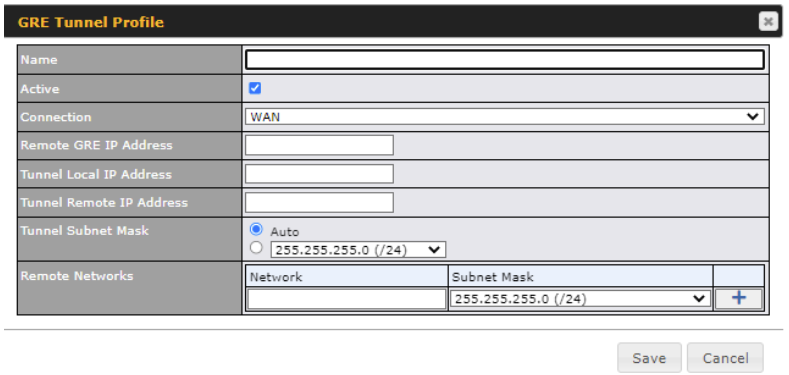
| GRE Tunnel Profile | |
| Name | This field is for specifying a name to represent this GRE Tunnel connection profile. |
| Active | When this box is checked, this GRE Tunnel connection profile will be enabled. Otherwise, it will be disabled. |
| Connection | Select the appropriate WAN connection from the drop-down menu. |
| Remote GRE IP Address | This field is for entering the remote GRE’s IP address |
| Tunnel Local IP Address | This field is for specifying the tunnel source IP address. |
| Tunnel Remote IP Address | This field is for specifying the tunnel destination IP address |
| Tunnel Subnet Mask | This field is to select the subnet mask that is to be used for the GRE tunnel. |
| Remote Networks | Input the LAN and subnets that are located at the remote site here. |
OpenVPN is a site to site VPN mode that can encapsulate a wide variety of network layer protocols inside virtual point-to-point links over an Internet Protocol network.
To configure a OpenVPN, navigate to Advanced > OpenVPN and click the New Profile.
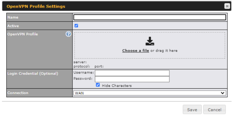
| OpenVPN Profile Settings | |
| Name | This field is for specifying a name to represent this OpenVPN profile. |
| Active | When this box is checked, this OpenVPN connection profile will be enabled. Otherwise, it will be disabled. |
| OpenVPN Profile | Upload the OpenVPN configuration (.ovpn) file from your service provider. |
| Login Credential (Optional) | This option is an optional for you to enter the username and password to login for the OpenVPN connection if the profile need to login. |
| Connection | Select the appropriate WAN connection from the drop-down menu. |
Pepwave routers can flexibly manage and load balance outbound traffic among WAN connections.
| Important Note |
| Outbound policies are applied only when more than one WAN connection is active. |
The settings for managing and load balancing outbound traffic are located at Advanced > Outbound Policy
The screenshot below shows the Outbound Policy window with Expert mode enabled.

The bottom-most rule HTPS_Peristence is Default. This rule manages the device’s default manner of controlling outbound traffic for all connections that do not match any of the rules above it.
To rearrange the priority of outbound rules, drag and drop them into the desired sequence.
Under Expert Mode, a special rule is displayed on the Custom Rules table which is “SpeedFusion VPN Routes”. It presents all PepVPN routes learned from remote VPN peers. By default, this bar is on the top of all custom rules. That means traffic for remote VPN subnets will be routed to its corresponding VPN peer. You can create custom Priority or Enforced rules and move them above the bar to override the PepVPN Routes.
Upon disabling the Expert Mode, all rules above the bar will be deleted.
Adding new Custom Outbound Policies
To add new custom rules (Outbound Policies) select Add Rule.
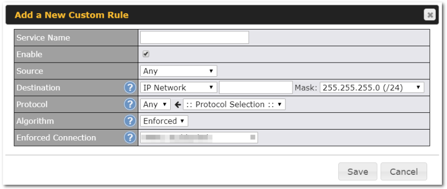
| Default Outbound Policy Settings | |
| Service Name | This field is for specifying a name to represent this profile. The name can be any combination of alphanumeric characters (0-9, A-Z, a-z), underscores (_), dashes (-), and/or non-leading/trailing spaces ( ). |
| Enable | When this box is checked, this outbound policy will be enabled. Otherwise, it will be disabled. |
| Source | This setting specifies the source IP address, IP network, MAC address, Client Type or Client’s Associated SSID for traffic that matches the rule.
|
| Destination | This setting specifies the destination IP address, IP network, Domain name for traffic that matches the rule.
|
| Protocol | This setting specifies the IP protocol and port of traffic that matches this rule. Via a drop-down menu, the following protocols can be specified:
Alternatively, the Protocol Selection Tool drop-down menu can be used to automatically fill in the protocol and port number of common Internet services (e.g., HTTP, HTTPS, etc.) After selecting an item from the Protocol Selection Tool drop-down menu, the protocol and port number remains manually modifiable. |
| Algorithm | This setting specifies the behavior of the Pepwave router for the custom rule.
One of the following values can be selected:
For a full explanation of each Algorithm, please see the following article: https://forum.peplink.com/t/exactly-how-do-peplinks-load-balancing-algorithmns-work/805 |
| Load Distribution Weight | This is to define the outbound traffic weight ratio for each WAN connection.. |
| When No Connections are Available | This field allows you to configure the default action when all the selected Connections are not available.
|
| Terminate Sessions on Connection Recovery | In the case when the highest priority connection is unavailable, matching sessions may routed through a lower priority connection or skipped to next matching rule (Fall-through to Next Rule). By checking this option, those sessions will be terminated upon connection recovery of any higher priority connections. Terminated sessions will go through all the rules again to determine the outgoing connection.
When Source is a MAC address, this option will be disabled automatically. Default: Disable |
Expert Mode is available on some Pepwave routers for use by advanced users. To enable the feature, click on the help icon and click turn on Expert Mode.
In Expert Mode, a new special rule, SpeedFusionTM Routes, is displayed in the Custom Rules table. This rule represents all SpeedFusionTM routes learned from remote VPN peers. By default, this bar is on the top of all custom rules. This position means that traffic for remote VPN subnets will be routed to the corresponding VPN peer. You can create custom Priority or Enforced rules and move them
above the bar to override the SpeedFusionTM routes.
Upon disabling Expert Mode, all rules above the bar will be removed.
Pepwave routers can act as a firewall that blocks, by default, all inbound access from the Internet. By using port forwarding, Internet users can access servers behind the Pepwave router. Inbound port forwarding rules can be defined at Advanced > Port Forwarding.
To define a new service, click Add Service.
| Port Forwarding Settings | |
| Enable | This setting specifies whether the inbound service takes effect. When Enable is checked, the inbound service takes effect: traffic is matched and actions are taken by the Pepwave router based on the other parameters of the rule. When this setting is disabled, the inbound service does not take effect: the Pepwave router disregards the other parameters of the rule. |
| Service Name | This setting identifies the service to the system administrator. Valid values for this setting consist of only alphanumeric and underscore “_” characters. |
| Protocol | The Protocol setting, along with the Port setting, specifies the protocol of the service as TCP, UDP, ICMP, or IP. Traffic that is received by the Pepwave router via the specified protocol at the specified port(s) is forwarded to the LAN hosts specified by the Servers setting. Please see below for details on the Port and Servers settings. Alternatively, the Protocol Selection Tool drop-down menu can be used to automatically fill in the protocol and a single port number of common Internet services (e.g. HTTP, HTTPS, etc.). After selecting an item from the Protocol Selection Tool drop-down menu, the protocol and port number remain manually modifiable. |
| Port |
The Port setting specifies the port(s) that correspond to the service, and can be configured to behave in one of the following manners:Any Port, Single Port, Port Range, Port Map, and Range Mapping Any Port: all traffic that is received by the Pepwave router via the specified protocol is forwarded to the servers specified by the Servers setting. For example, with IP Protocol set to TCP, and Port set to Any Port, all TCP traffic is forwarded to the configured servers. Single Port: traffic that is received by the Pepwave router via the specified protocol at the specified port is forwarded via the same port to the servers specified by the Servers setting. For example, with IP Protocol set to TCP, and Port set to Single Port and Service Port 80, TCP traffic received on port 80 is forwarded to the configured servers via port 80. Port Range: traffic that is received by the Pepwave router via the specified protocol at the specified port range is forwarded via the same respective ports to the LAN hosts specified by the Servers setting. For example, with IP Protocol set to TCP, and Port set to Port Range and Service Ports 80-88, TCP traffic received on ports 80 through 88 is forwarded to the configured servers via the respective ports. Port Mapping: traffic that is received by Pepwave router via the specified protocol at the specified port is forwarded via a different port to the servers specified by the Servers setting. For example, with IP Protocol set to TCP, and Port set to Port Mapping, Service Port 80, and Map to Port 88, TCP traffic on port 80 is forwarded to the configured servers via port 88.(Please see below for details on the Servers setting.) Range Mapping: traffic that is received by the Pepwave router via the specified protocol at the specified port range is forwarded via a different port to the servers specified by the Servers setting. |
UPnP and NAT-PMP are network protocols which allow a computer connected to a LAN port or WiFi AP to automatically configure the router to allow parties on the WAN port to connect to itself. That way, the process of inbound port forwarding becomes automated.
When a computer creates a rule using these protocols, the specified TCP/UDP port of all WAN connections’ default IP address will be forwarded.
Check the corresponding box(es) to enable UPnP and/or NAT-PMP. Enable these features only if you trust the computers connected to a LAN port or WiFi AP.
When the options are enabled, a table listing all the forwarded ports under these two protocols can be found at Status>UPnP / NAT-PMP.
In the example above, the UPnP device is running. When the UPnP device is disconnected, the router will suspend the service and incoming traffic will be dropped (without error/notification message). The UPnP rule will remain for an interval after the UPnP device is disconnected before being removed.
NAT mappings allow IP address mapping of all inbound and outbound NAT’d traffic to and from an internal client IP address. Settings to configure NAT mappings are located at Advanced>NAT Mappings.

To add a rule for NAT mappings, click Add NAT Rule.
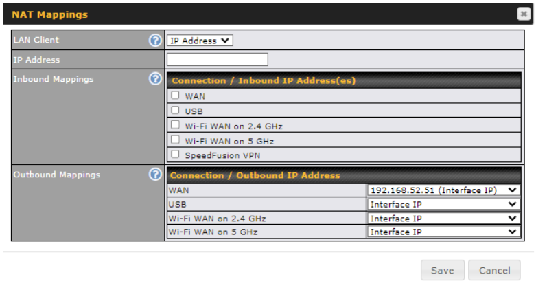
| NAT Mapping Settings | |
| LAN Client | NAT mapping rules can be defined for a single LAN IP Address, an IP Range, or an IP Network. |
| IP Address | This refers to the LAN host’s private IP address. The system maps this address to a number of public IP addresses (specified below) in order to facilitate inbound and outbound traffic. This option is only available when IP Address is selected. |
| IP Range | The IP range is a contiguous group of private IP addresses used by the LAN host. The system maps these addresses to a number of public IP addresses (specified below) to facilitate outbound traffic. This option is only available when IP Range is selected. |
| IP Network | The IP network refers to all private IP addresses and ranges managed by the LAN host. The system maps these addresses to a number of public IP addresses (specified below) to facilitate outbound traffic. This option is only available when IP Network is selected. |
| Inbound Mappings | This setting specifies the WAN connections and corresponding WAN-specific Internet IP addresses on which the system should bind. Any access to the specified WAN connection(s) and IP address(es) will be forwarded to the LAN host. This option is only available when IP Address is selected in the LAN Client(s) field.
Note that inbound mapping is not needed for WAN connections in drop-in mode or IP forwarding mode. Also note that each WAN IP address can be associated to one NAT mapping only. |
| Outbound Mappings | This setting specifies the WAN IP addresses that should be used when an IP connection is made from a LAN host to the Internet. Each LAN host in an IP range or IP network will be evenly mapped to one of each selected WAN’s IP addresses (for better IP address utilization) in a persistent manner (for better application compatibility).
Note that if you do not want to use a specific WAN for outgoing accesses, you should still choose default here, then customize the outbound access rule in the Outbound Policy section. Also note that WAN connections in drop-in mode or IP forwarding mode are not shown here. |
Click Save to save the settings when configuration has been completed.
| Important Note |
| Inbound firewall rules override the Inbound Mappings settings. |
LAN and PPTP clients can be categorized into three user groups: Manager, Staff, and Guest. This menu allows you to define rules and assign client IP addresses or subnets to a user group. You can apply different bandwidth and traffic prioritization policies on each user group in the Bandwidth Control and Application sections (note that the options available here vary by model).
The table is automatically sorted by rule precedence. The smaller and more specific subnets are put towards the top of the table and have higher precedence; larger and less specific subnets are placed towards the bottom.
Click the Add button to define clients and their user group. Click the ![]() button to remove the defined rule. Two default rules are pre-defined and put at the bottom. They are All DHCP reservation clients and Everyone, and they cannot be removed. The All DHCP reservation client represents the LAN clients defined in the DHCP Reservation table on the LAN settings page. Everyone represents all clients that are not defined in any rule above. Click on a rule to change its group.
button to remove the defined rule. Two default rules are pre-defined and put at the bottom. They are All DHCP reservation clients and Everyone, and they cannot be removed. The All DHCP reservation client represents the LAN clients defined in the DHCP Reservation table on the LAN settings page. Everyone represents all clients that are not defined in any rule above. Click on a rule to change its group.

| Add / Edit User Group | |
| Grouped by | From the drop-down menu, choose whether you are going to define the client(s) by an IP Address or a Subnet. If IP Address is selected, enter a name defined in DHCP reservation table or a LAN client’s IP address. If Subnet is selected, enter a subnet address and specify its subnet mask. |
| User Group | This field is to define which User Group the specified subnet / IP address belongs to. |
Once users have been assigned to a user group, their internet traffic will be restricted by rules defined for that particular group. Please refer to the following two sections for details.
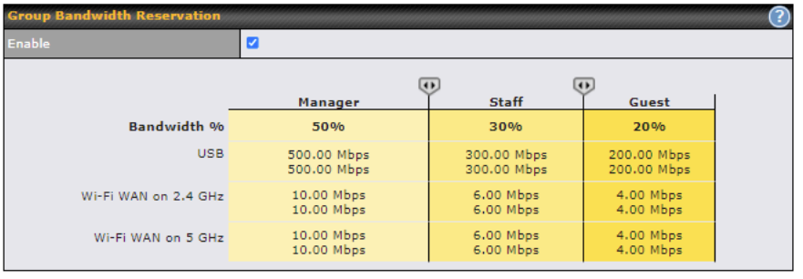
This section is to define how much minimum bandwidth will be reserved to each user group when a WAN connection is in full load. When this feature is enabled, a slider with two indicators will be shown. You can move the indicators to adjust each group’s weighting. The lower part of the table shows the corresponding reserved download and uploads bandwidth value of each connection.
By default, 50% of bandwidth has been reserved for Manager, 30% for Staff, and 20% for Guest.
The default download and upload limits are set to unlimited (set as 0). This can be changed as necessary to restrict the speeds to individual devices connected to the router, either wired or wireless. Note, this limit is applied to all devices.

This section is to define the QoS Application Queue. You can set guaranteed bandwidth for a queue and assign it to applications.

Click the Add button to create the QoS Application Queue.

| Add Queue | |
| Name | This setting specifies a name for the QoS Application Queue. |
| Bandwidth | Bandwidth to be reserved (for each WAN connection) for this queue. When WAN is congested, this bandwidth will remain available for applications assigned to this queue. |
| Borrow Spare Bandwidth | Enable this option if you want this queue to utilize WAN’s unused bandwidth. |
Three application priority levels can be set: ↑High,━ Normal, and↓Low. Pepwave routers can detect various application traffic types by inspecting the packet content. Select an application by choosing a supported application, or by defining a custom application manually. The priority preference of supported applications is placed at the top of the table. Custom applications are at the bottom.
Click the Add button to define a custom application. Click the button in the Action column to delete the custom application in the corresponding row.
When Supported Applications is selected, the Pepwave router will inspect network traffic and prioritize the selected applications. Alternatively, you can select Custom Applications and define the application by providing the protocol, scope, port number, and DSCP value.
DSL/cable-based WAN connections have lower upload bandwidth and higher download bandwidth. When a DSL/cable circuit’s uplink is congested, the download bandwidth will be affected. Users will not be able to download data at full speed until the uplink becomes less congested. DSL/Cable Optimization can relieve such an issue. When it is enabled, the download speed will become less affected by the upload traffic. By default, this feature is enabled.
Enable this option to grant PepVPN traffic the highest priority when WAN is congested.
A firewall is a mechanism that selectively filters data traffic between the WAN side (the Internet) and the LAN side of the network. It can protect the local network from potential hacker attacks, access to offensive websites, and/or other inappropriate uses.
The firewall functionality of Pepwave routers supports the selective filtering of data traffic in both directions:
The firewall also supports the following functionality:
Outbound Firewall Rules
The outbound firewall settings are located at Advanced > Firewall > Access Rules.

To enable or disable the Outbound Firewall to manage device local network traffic, click on the help icon ![]() and click here, the sceen will shown below.
and click here, the sceen will shown below.

| Note |
| To utilize the Outbound Firewall Rule to block the Peplink device from contacting InControl 2. may refer to the link below:
https://forum.peplink.com/t/faq-prevent-device-reaching-incontrol-2./63f48fdfd466df34ab475f55/ |
Click Add Rule to display the following screen:
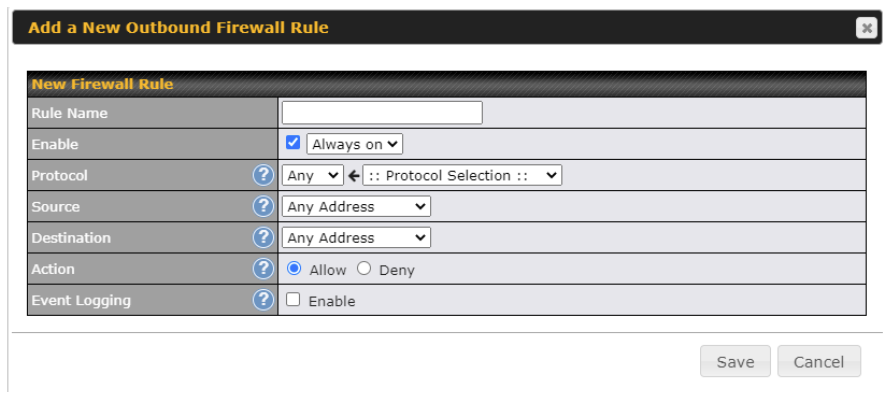
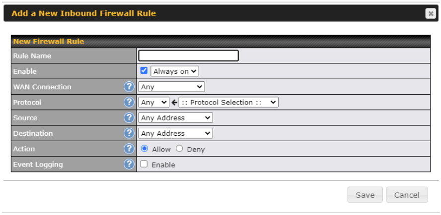
Inbound Firewall Rules
Inbound firewall settings are located at Advanced > Firewall > Access Rules.

Click Add Rule to display the following screen:
Internal Firewall Rules
Internal Network Firewall settings are located at Advanced > Firewall > Access Rules.

Click Add Rule to display the following screen:
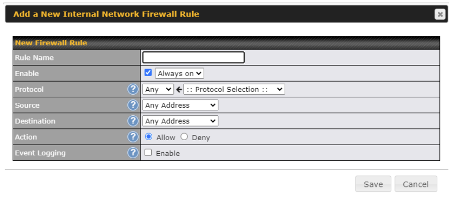
| Inbound / Outbound / Internal Network Firewall Settings | |
| Rule Name | This setting specifies a name for the firewall rule. |
| Enable | This setting specifies whether the firewall rule should take effect. If the box is checked, the firewall rule takes effect. If the traffic matches the specified protocol/IP/port, actions will be taken by the Pepwave router based on the other parameters of the rule. If the box is not checked, the firewall rule does not take effect. The Pepwave router will disregard the other parameters of the rule.
Click the dropdown menu next to the checkbox to place this firewall rule on a time schedule. |
| WAN Connection (Inbound) | Select the WAN connection that this firewall rule should apply to. |
| Protocol | This setting specifies the protocol to be matched. Via a drop-down menu, the following protocols can be specified:
Alternatively, the Protocol Selection Tool drop-down menu can be used to automatically fill in the protocol and port number of common Internet services (e.g., HTTP, HTTPS, etc.) After selecting an item from the Protocol Selection Tool drop-down menu, the protocol and port number remains manually modifiable. |
| Source IP & Port | This specifies the source IP address(es) and port number(s) to be matched for the firewall rule. A single address, Network, MAC Address or Grouped Network can be specified as the Source setting. |
| Destination IP & Port | This specifies the destination IP address(es) and port number(s) to be matched for the firewall rule. A single address, Network, MAC Address or a Grouped Network, can be specified as the Destination setting. |
| Action | This option allows you to define whether to allow or deny an IP session matching this Firewall Rule |
| Event Logging | This setting specifies whether or not to log matched firewall events. The logged messages are shown on the page Status>Event Log. A sample message is as follows:
Aug 13 23:47:44 Denied CONN=Ethernet WAN SRC=20.3.2.1 DST=192.168.1.20 LEN=48 PROTO=TCP SPT=2260 DPT=80 ● CONN: The connection where the log entry refers to ● SRC: Source IP address ● DST: Destination IP address ● LEN: Packet length ● PROTO: Protocol ● SPT: Source port ● DPT: Destination port |
Click Save to store your changes. To create an additional firewall rule, click the Add Rule and repeat the above steps.
To change a rule’s priority, simply drag and drop the rule:

To remove a rule, click the ![]() button.
button.
Rules are matched from top to bottom. If a connection matches any one of the upper rules, the matching process will stop. If none of the rules match, the Default rule will be applied. By default, the Default rule is set as Allow for Outbound, Inbound and Internal Network access.
| Tip |
| If the default inbound rule is set to Allow for NAT-enabled WANs, no inbound Allow firewall rules will be required for inbound port forwarding and inbound NAT mapping rules. However, if the default inbound rule is set as Deny, a corresponding Allow firewall rule will be required. |
Intrusion Detection and DoS Prevention
Pepwave routers can detect and prevent intrusions and denial-of-service (DoS) attacks from the Internet. To turn on this feature, click , check the Enable check box, and press the Save button.
When this feature is enabled, the Pepwave router will detect and prevent the following kinds of intrusions and denial-of-service attacks.
Local Service Firewall settings are located at Advanced > Firewall > Access Rules.

Click Add Rule to display the following window:
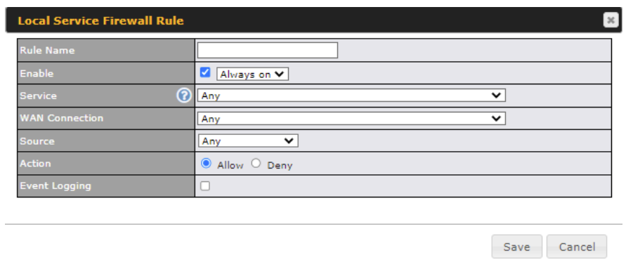
| Local Service Firewall Settings | |
| Rule Name | This setting specifies a name for the firewall rule. |
| Enable | This setting specifies whether the firewall rule should take effect. If the box is checked, the firewall rule takes effect. If the traffic matches the specified protocol/IP/port, actions will be taken by the Pepwave router based on the other parameters of the rule. If the box is not checked, the firewall rule does not take effect. The Pepwave router will disregard the other parameters of the rule.
Click the dropdown menu next to the checkbox to place this firewall rule on a time schedule. |
| Service | This option allows you to define the supported local service to be matched.
If Any is chosen, the firewall rule will match to all supported local services from the list. Via a drop-down menu, the following services can be specified:
|
| WAN Connection | Select the WAN connection that this firewall rule should apply to. |
| Source | This specifies the source IP address and IP Network to be matched for the firewall rule. |
| Action | With the value of Allow for the Action setting, the matching traffic passes through the router (to be routed to the destination). If the value of the Action setting is set to Deny, the matching traffic does not pass through the router (and is discarded). |
| Event Logging | This setting specifies whether or not to log matched firewall events. The logged messages are shown on the page Status>Event Log. A sample message is as follows:
Aug 13 23:47:44 Denied CONN=Ethernet WAN SRC=20.3.2.1 DST=192.168.1.20 LEN=48 PROTO=TCP SPT=2260 DPT=80
|
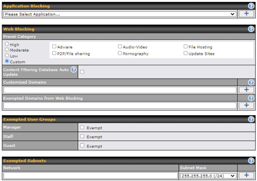
Choose applications to be blocked from LAN/PPTP/SpeedFusion VPN peer clients’ access, except for those on the Exempted User Groups or Exempted Subnets defined below.
Defines website domain names to be blocked from LAN/PPTP/SpeedFusion VPN peer clients’ access except for those on the Exempted User Groups or Exempted Subnets defined below.
If “foobar.com” is entered, any web site with a host name ending in foobar.com will be blocked, e.g. www.foobar.com, foobar.com, etc. However, “myfoobar.com” will not be blocked.
You may enter the wild card “.*” at the end of a domain name to block any web site with a host name having the domain name in the middle. If you enter “foobar.*”, then “www.foobar.com”, “www.foobar.co.jp”, or “foobar.co.uk” will be blocked. Placing the wild card in any other position is not supported.
The device will inspect and look for blocked domain names on all HTTP and HTTPS traffic.
Check and select pre-defined user group(s) who can be exempted from the access blocking rules. User groups can be defined at QoS>User Groups section. Please refer to Section 17.1 for details.
With the subnet defined in the field, clients on the particular subnet(s) will be exempted from the Web blocking rules.
The Pepwave Surf SOHO supports OSPF ,RIPv2 and BGP dynamic routing protocols.
Click the Advanced tab from the top bar, and then click the Routing Protocols > OSPF & RIPv2 item on the sidebar to reach the following menu.

|
OSPF |
|
|
Router ID |
This field determines the ID of the router. By default, this is specified as the LAN IP address. If you want to specify your own ID, enter it in the Custom field. |
|
Area |
This is an overview of the OSPFv2 areas you have defined. Click on the area name to configure it. To set a new area, click Add. To delete an existing area, click |

|
OSPF Settings |
|
|
Area ID |
Determine the name of your Area ID to apply to this group. Machines linked to this group will send and receive related OSPF packets, while unlinked machines will ignore it. |
|
Link Type |
Choose the network type that this area will use. |
|
Authentication |
Choose an authentication method, if one is used, from this drop-down menu. Available options are MD5 and Text. Enter the authentication key next to the drop-down menu. |
|
Interfaces |
Determine which interfaces this area will use to listen to and deliver OSPF packets |
|
Interface Cost |
Enable the advanced option (question mark) to be able to configure a custom cost for each interface. |
To access RIPv2 settings, click ![]() .
.

|
RIPv2 Settings |
|
|
Authentication |
Choose an authentication method, if one is used, from this drop-down menu. Available options are MD5 and Text. Enter the authentication key next to the drop-down menu. |
|
Interfaces |
Determine which interfaces this group will use to listen to and deliver RIPv2 packets. |

|
OSPF & RIPv2 Route Advertisement |
|
|
SpeedFusion VPN Route Isolation |
Enable this option if you want to isolate PepVPN peers from each other. Received PepVPN routes will not be forwarded to other PepVPN peers to reduce bandwidth consumption. Note: This will only hide routing information between PepVPN peers, if you want to fully block inter-PepVPN traffics, you should configure Firewall rules instead. |
|
Network Advertising |
Selected networks will be advertised over OSPF & RIPv2. If no network is selected, all LAN / VLAN networks will be advertised by default. All the networks belonging to interfaces that have OSPF or RIPv2 enabled will be advertised even if they are not selected in this table. |
|
Static Route Advertising |
Enable this option to advertise LAN static routes over OSPF & RIPv2. Static routes that match the Excluded Networks table will not be advertised. |
BGP (Border Gateway Protocol) is a protocol that manages how packets are routed across the internet through the exchange of routing and reachability information between edge routers. BGP directs packets between autonomous systems (AS) — networks managed by a single enterprise or service provider.
Click the Network tab from the top bar, and then click the BGP item on the sidebar to configure BGP.
Click “x” to delete a BGP profile
Click “Add” to add a new BGP profile
|
BGP Profile |
|
|
Name |
This field is for specifying a name to represent this profile. |
|
Enable |
When this box is checked, this BGP profile will be enabled. |
|
Interface |
The interface in which the BGP neighbor is located. |
|
Autonomous System |
The Autonomous System Number (ASN) assigned to this profile. |
|
Neighbor |
BGP Neighbors and their details. |
|
IP address |
The IP address of the Neighbor. |
|
Autonomous System |
The Neighbor’s ASN. |
|
Multihop/TTL |
This field determines the Time-to-live (TTL) of BGP packets. |
|
Password |
(Optional) Assign a password for MD5 authentication of BGP sessions. |
|
AS-Path Prepending: |
AS path to be prepended to the routes received from this Neighbor. For example: inputting “64530,64531” will prepend “64530, 64531” to received routes. |
|
Hold Time |
Wait time in seconds for a keepalive message from a Neighbor before considering the BGP connection as stalled. The value must be either 0 (infinite hold time) or between 3 and 65535 inclusively. Default: 240 |
|
Next Hop Self |
Enable this option to advertise your own source address as the next hop when propagating routes. |
|
iBGP Local Preference |
This is the metric advertised to iBGP Neighbors to indicate the preference for external routes. The value must be between 0 to 4294967295 inclusively. Default: 100 |
|
BFD |
Enable this option to add Bidirectional Forwarding Detection for path failure. All directly connected Neighbors that use the same physical interface share the same BFD settings. All mulithop Neighbors share the same multihop BFD settings. You can configure BFD settings in the BGP profile listing page after this option is enabled. |

|
Route Advertisement Settings |
|
|
Network Advertising |
Select the Networks that will be advertised to the BGP Neighbor. |
|
Static Route Advertising |
Enable this option to advertise static LAN routes. Static routes that match the Excluded Networks table will not be advertised. |
|
Custom Route Advertising |
Additional routes to be advertised to the BGP Neighbor. |
|
Advertise OSPF Route |
When this box is checked, every learnt OSPF route will be advertised. |
|
Set Community |
Assign a prefix to a Community Community: Two numbers in new-format. e.g. 65000:21344 Well-known communities: no-export 65535:65281 no-advertise 65535:65282 no-export-subconfed 65535:65283 no-peer 65535:65284 Route Prefix: Comma separated networks. e.g. 172.168.1.0/24,192.168.1.0/28 |
| Filter Mode | This field allows for the selection of the filter mode for route import.None: All BGP routes will be accepted.Accept: Routes in “Restricted Networks” will be accepted, routes not in the list will be rejected.Reject: Routes in “Restricted Networks” will be rejected, routes not in the list will be accepted. |
| Restricted / Blocked Networks | This field specifies the network(s) in the “route import” entry.Exact Match: When this box is checked, only routes with the same Network and Subnet Mask will be filtered. Otherwise, routes within the Networks and Subnets will be filtered. |
|
Filter Mode |
This field allows for the selection of the filter mode for route export. None: All BGP routes will be accepted. Accept: Routes in “Restricted Networks” will be accepted, routes not in the list will be rejected. Reject: Routes in “Restricted Networks” will be rejected, routes not in the list will be accepted. |
|
Restricted / Blocked Networks |
This field specifies the network(s) in the “route export” entry. Exact Match: When this box is checked, only routes with the same Network and Subnet Mask will be filtered. |
|
Export to other BGP Profile |
When this box is checked, routes learnt from this BGP profile will be exported to other BGP profiles. |
|
Export to OSPF |
When this box is checked, routes learnt from this BGP profile will be exported to the OSPF routing protocol. |
A remote-access VPN connection allows an individual user to connect to a private business network from a remote location using a laptop or desktop computer connected to the Internet. Networks routed by a Peplink router can be remotely accessed via OpenVPN, L2TP with IPsec or PPTP. To configure this feature, navigate to Advanced > Remote User Access and choose the required VPN type.

| L2TP with IPsec | |
| Pre-shared Key | Enter your pre shared key in the text field. Please note that remote devices will need this preshared key to access the Balance. |
| Disable Weak Ciphers | Click the When checked, weak ciphers such as 3DES will be disabled. |
| Listen On | This setting is for specifying the WAN IP addresses that allow remote user access. |
Continue to configure the authentication method.

Select OpenVPN and continue to configure the authentication method.
The OpenVPN Client profile can be downloaded from the Status > device page after the configuration has been saved.
![]()
You have a choice between 2 different OpenVPN Client profiles.

No additional configuration required.
The Point-to-Point Tunneling Protocol (PPTP) is an obsolete method for implementing virtual private networks. PPTP has many well known security issues
Continue to configure authentication methods.

| Authentication Method | |
| Connect to Network | Select the VLAN network for remote users to enable remote user access on. |
| User Accounts | This setting allows you to define the Remote User Accounts. Click Add to input username and password to create an account. After adding the user accounts, you can click on a username to edit the account password. Note: The username must contain lowercase letters, numerics, underscores(_), dash(-), at sign(@), and period(.) only.
|
RADIUS Server settings are located at Advanced > Misc. Settings > RADIUS Server.

Click New Profile to display the following screen:
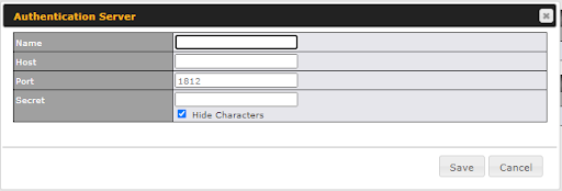
| Authentication Server | |
| Name | This field is for specifying a name to represent this profile. |
| Host | Specifies the IP address or hostname of the RADIUS server host. |
| Authentication Port | This setting specifies the UDP destination port for authentication requests. By default, the port number is 1812. |
| Secret | This field is for entering the secret key for communicating to the RADIUS server. |
| Accounting Port | This setting specifies the UDP destination port for accounting requests. By default, the port number is 1813. |
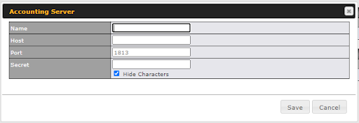
| Accounting Server | |
| Name | This field is for specifying a name to represent this profile. |
| Host | Specifies the IP address or hostname of the RADIUS server host. |
| Authentication Port | This setting specifies the UDP destination port for authentication requests. By default, the port number is 1812. |
| Secret | This field is for entering the secret key for communicating to the RADIUS server. |
| Accounting Port | This setting specifies the UDP destination port for accounting requests. By default, the port number is 1813. |
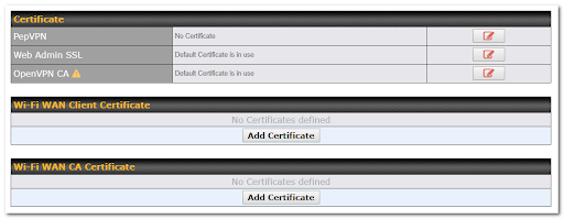
This section allows you to assign certificates for the local VPN, OpenVPN, Captive Portal, Mediafast, Contenthub, Wi-Fi WAN (Client and CA) and web admin SSL for extra security.
Read the following knowledgebase article for full instructions on how to create and import a self-signed certificate: https://forum.peplink.com/t/how-to-create-a-self-signed-certificate-and-import-it-to-a-peplink-product/
Service forwarding settings are located at Advanced > Misc. Settings > Service Forwarding.
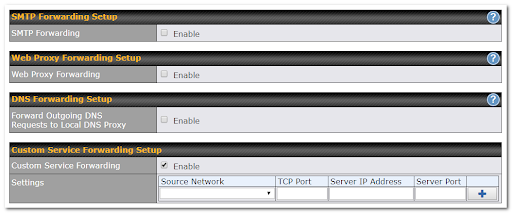
Some ISPs require their users to send emails via the ISP’s SMTP server. All outgoing SMTP connections are blocked except those connecting to the ISP’s. Pepwave routers support intercepting and redirecting all outgoing SMTP connections (destined for TCP port 25) via a WAN connection to the WAN’s corresponding SMTP server.
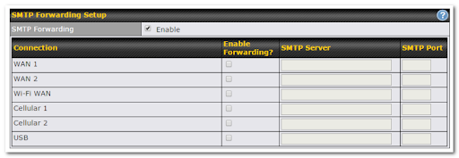
To enable the feature, select Enable under SMTP Forwarding Setup. Check Enable Forwarding for the WAN connection(s) that needs forwarding. Under SMTP Server, enter the ISP’s email server hostname or IP address. Under SMTP Port, enter the TCP port number for each WAN.
The Pepwave router will intercept SMTP connections. Choose a WAN port according to the outbound policy, and then forward the connection to the SMTP server if the chosen WAN has enabled forwarding. If the forwarding is disabled for a WAN connection, SMTP connections for the WAN will be simply be forwarded to the connection’s original destination.
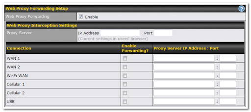
When this feature is enabled, the Pepwave router will intercept all outgoing connections destined for the proxy server specified in Web Proxy Interception Settings, choose a WAN connection with reference to the outbound policy, and then forward them to the specified web proxy server and port number. Redirected server settings for each WAN can be set here. If forwarding is disabled for a WAN, web proxy connections for the WAN will be simply forwarded to the connection’s original destination.

When DNS forwarding is enabled, all clients’ outgoing DNS requests will also be intercepted and forwarded to the built-in DNS proxy server.

After clicking the enable checkbox, enter your TCP port for traffic heading to the router, and then specify the IP Address and Port of the server you wish to forward the service to.
Service passthrough settings can be found at Advanced > Misc. Settings > Service Passthrough.
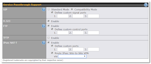
Some Internet services need to be specially handled in a multi-WAN environment. Pepwave routers can handle these services such that Internet applications do not notice being behind a multi-WAN router. Settings for service passthrough support are available here.
| Service Passthrough Support | |
|---|---|
| SIP | Session initiation protocol, aka SIP, is a voice-over-IP protocol. The Pepwave router can act as a SIP application layer gateway (ALG) which binds connections for the same SIP session to the same WAN connection and translate IP address in the SIP packets correctly in NAT mode. Such passthrough support is always enabled, and there are two modes for selection: Standard Mode and Compatibility Mode. If your SIP server’s signal port number is non-standard, you can check the box Define custom signal ports and input the port numbers to the text boxes. |
| H.323 | With this option enabled, protocols that provide audio-visual communication sessions will be defined on any packet network and pass through the Pepwave router. |
| FTP | FTP sessions consist of two TCP connections; one for control and one for data. In a multi-WAN situation, they must be routed to the same WAN connection. Otherwise, problems will arise in transferring files. By default, the Pepwave router monitors TCP control connections on port 21 for any FTP connections and binds TCP connections of the same FTP session to the same WAN. If you have an FTP server listening on a port number other than 21, you can check Define custom control ports and enter the port numbers in the text boxes. |
| TFTP | The Pepwave router monitors outgoing TFTP connections and routes any incoming TFTP data packets back to the client. Select Enable if you want to enable TFTP passthrough support. |
| Service Passthrough Support | |
| SIP | Session initiation protocol, aka SIP, is a voice-over-IP protocol. The Pepwave router can act as a SIP application layer gateway (ALG) which binds connections for the same SIP session to the same WAN connection and translate IP address in the SIP packets correctly in NAT mode. Such passthrough support is always enabled, and there are two modes for selection: Standard Mode and Compatibility Mode. If your SIP server’s signal port number is non-standard, you can check the box Define custom signal ports and input the port numbers to the text boxes. |
| IPsec NAT-T | This field is for enabling the support of IPsec NAT-T passthrough. UDP ports 500, 4500, and 10000 are monitored by default. You may add more custom data ports that your IPsec system uses by checking Define custom ports. If the VPN contains IPsec site-to-site VPN traffic, check Route IPsec Site-to-Site VPN and choose the WAN connection to route the traffic to. |

Using “Grouped Networks” you can group and name a range of IP addresses, which can then be used to define firewall rules or outbound policies.
Start by clicking on “add group” then fill in the appropriate fields.
In this example we’ll create a group “accounting”
Click save when you have finished adding the required networks.

The grouped network “accounting” can now be used to configure a group policy or firewall rule.
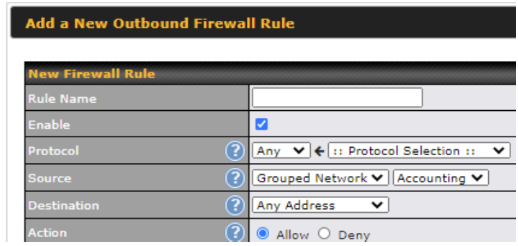
The SIM Toolkit, accessible via Advanced>Settings>SIM Toolkit supports two functionalities, USSD and SMS.
![]()
Unstructured Supplementary Service Data (USSD) is a protocol used by mobile phones to communicate with their service provider’s computers. One of the most common uses is to query the available balance.

Enter your USSD code under the USSD Code text field and click Submit.

You will receive a confirmation. To check the SMS response, click Get.

After a few minutes you will receive a response to your USSD code

The SMS option allows you to read SMS (text) messages that have been sent to the SIM in your Peplink routers.

You may define the UDP reply by clicking the Advanced > Misc Setting > UDP Relay. You can click ![]() to enable the UPD Broadcast or Multicast traffic for LAN/VLAN/SpeedFusion VPN.
to enable the UPD Broadcast or Multicast traffic for LAN/VLAN/SpeedFusion VPN.

Click “New UDP Relay Rule” to define the relay rule.
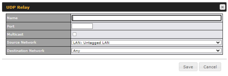
| UDP Relay | |
| Name | This field is for specifying a name to represent this profile. |
| Port | This feid is to enter the specific port number for the UDP relay |
| Multicast | If Multicast is not selected, it will broadcast relay rule. If Multicast is selected, you may need to enter a valid multicast address. |
| Secure Network | Select the specific connection as a source network to where the device is to relay UDP Broadcast packets. |
| Destination Network | You may select the specific connection from the drop-down list or may custom combination network as a destination network that receives the UDP packet relays. |
Use the controls on the AP tab to set the wireless SSID and AP settings.
Wireless network settings, including the name of the network (SSID) and security policy can be defined and managed in this section via AP > Wireless SSID

Click New SSID to create a new network profile, or click the existing network profile to modify its settings.
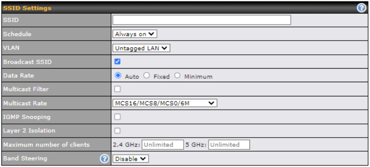
| SSID Settings | |
| SSID | This setting specifies the Router SSID that Wi-Fi clients will see when scanning. |
| Schedule | Click the drop-down menu to choose predefined schedules as your starting point. Please note that upon selection, previous changes on the schedule map will be deleted. |
| VLAN | Some service providers require the router to enable VLAN tagging for Internet traffic. If it is required by your service provider, you can enable this field and enter the VLAN ID that the provider requires. |
| Broadcast SSID | This setting specifies whether or not Wi-Fi clients can scan the SSID of this wireless network. Broadcast SSID is enabled by default. |
| Data Rate | Select Auto to allow your access point to set the data rate automatically, or select Fixed and choose a rate from the drop-down menu. Click the MCS Index link to display a reference table containing MCS and matching HT20 and HT40 values. |
| Multicast Filter | This setting enables the filtering of multicast network traffic to the wireless SSID. |
| Multicast Rate | This setting specifies the transmit rate to be used for sending multicast network traffic. |
| IGMP Snooping | To allow your access point to convert multicast traffic to unicast traffic for associated clients, select this option. |
| Layer 2 Isolation | Layer 2 refers to the second layer in the ISO Open System Interconnect model.
When this option is enabled, it will block communication between Wi-Fi clients within the same VLAN, SSID or subnet, as a security measure that best suits a company Guest/Visitor Wi-Fi access scenario. Do refer to this link (https://forum.peplink.com/t/lan-isolation-with-balance30-and-ap-one-ac-mini-help-needed/3914/3) for visual illustration of the feature. By default, the setting is disabled. |
| Maximum number of Clients | Enter the maximum number of clients that can simultaneously connect to your SSID, or enter 0 to allow unlimited Wi-Fi clients. |
| Band Steering | To reduce 2.4 GHz band overcrowding, AP with band steering steers clients capable of 5 GHz operation to 5 GHz frequency.
Force – Clients capable of 5 GHz operation are only offered with 5 GHz frequency. Prefer – Clients capable of 5 GHz operation are encouraged to associate with 5 GHz frequency. If the clients insist to attempt on 2.4 GHz frequency, 2.4 GHz frequency will be offered. Default: Disable |
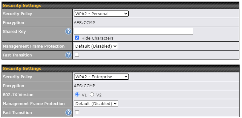
| Security Settings | |
|---|---|
| Security Policy | This setting configures the wireless authentication and encryption methods. Available options: :
When WPA/WPA2 – Enterprise is selected, RADIUS-based 802.1 x authentication is enabled. Under this configuration, the Shared Key option does not apply and is therefore hidden. When using this method, select the appropriate version using the V1/V2 controls. The security level of this method is known to be very high. When WPA/WPA2 – Personal is selected, a shared key is used for data encryption and authentication. When using this configuration, the Shared Key option should be enabled. Key length must be between eight and 63 characters (inclusive). The security level of this method is known to be high. NOTE: When WPA2/WPA3- Personal is configured, if a managed AP which is NOT WPA3 PSK capable, the AP Controller will not push those WPA3 and WPA2/WPA3 SSID to that AP. |
| Management Frame Protection | This feature protects stations against forged management frames spoofed from other devices.
Frames that are protected include Disassociation, Deauthentication and QoS Action. |
| Fast Transition | When WPA2/WPA3 – (Personal / Enterprise) is selected, the Fast Transition option is the standard defined for 801.11r to reduce the association process when it roams from one Access Point to another Access Point. |

| Access Control | |
| Restricted Mode | The settings allow administrators to control access using Mac address filtering. Available options are None, Deny all except listed, Accept all except and RADIUS MAC Authentication. |
| MAC Address List | Connections originating from the MAC addresses in this list will be either denied or accepted based on the option selected in the previous field. |
When the RADIUS MAC Authentication is selected in Restricted Mode, the RADIUS Settings will be showing:
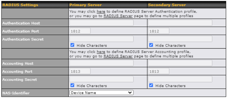
| RADIUS Server | |
| Host | Specifies the IP address or hostname of the RADIUS server host. |
| Secret | This field is for entering the secret key for communicating to the RADIUS server. |
| Authentication Port | This setting specifies the UDP destination port for authentication requests. By default, the port number is 1812. |
| Accounting Port | This setting specifies the UDP destination port for accounting requests. By default, the port number is 1813. |
| NAS-Identifier | The setting allows administrators to identify the client to the RADIUS server.
Available options are Device Name, LAN Mac Address Device Serial Number and Custom Value. |

| RADIUS Server | |
| Block All Private IP | Check this box to deny all connection attempts by private IP addresses. |
| Custom Subnet | To create a custom subnet for guest access, enter the IP address and choose a subnet mask from the drop-down menu. |
| Block Exception | To block access from a particular subnet, enter the IP address and choose a subnet mask from the drop-down menu. |

| Firewall Settings | |
| Firewall Mode | The settings allow administrator to control access to the SSID based on Firewall Rules.
Available options are Disable,Lockdown – Block all except… and Flexible –Allow all except… |
| Firewall Exceptions | Create Firewall Rules based on Port, IP Network, MAC address or Domain Name |
Wireless Mesh Support is available on devices running 802.11ac (Wi-Fi 5) and above. Along with the AP Controller, mesh network extensions can be established, which can expand network coverage. Note that the Wireless Mesh settings need to match the Mesh ID and Shared Key of the other devices on the same selected frequency band.

To create a new Wireless Mesh profile, go to AP > Wireless Mesh, and click Add.

| Wireless Mesh Settings | |
| Mesh ID | Enter a name to represent the Mesh profile. |
| Frequency | Select the 2.4GHz or 5GHz frequency to be used. |
| Shared Key | Enter the shared key in the text field. Please note that it needs to match the shared keys of the other APs in the Wireless Mesh settings.
Click Hide / Show Characters to toggle visibility. |
Navigating to AP>Settings displays a screen similar to the one shown below:
| Wi-Fi AP Settings | |
| SSID | Select if an SSID is broadcasting on 2.4 Ghz, 5 Ghz or both bands |
| Operating Country | This option sets the country whose regulations the Pepwave router follows. |
| Protocol | This option allows you to specify which client association requests will be accepted. By default, 802.11ng is selected. |
| Channel Width | Settings for 2.4 GHz AP and 5GHz AP can be configured here: 2.4 GHz: 40 MHz, 20/40 MHz and 20 MHz are available. The default setting is 20/40 MHz, which allows both widths to be used simultaneously. 80 MHz , 40 Mhz, 20 Mhz, and(20/40 MH) are available. The default setting is 80 MHz. Note: 802.11ng and 802.11na are not part of the 802.11 standard. It is simply a notation for indicating 802.11n use on the 2.4-GHz band (11ng) or 802.11n use on the 5-GHz band (11na). |
| Channel | This option allows you to select which 802.11 RF channel will be used. |
| Auto Channel Update | Indicate the time of day for updating the automatic channel selection. |
| Output Power | This option is for specifying the transmission output power for the Wi-Fi AP. There are 4 relative power levels available – Max, High, Mid, and Low. The actual output power will be bound by the regulatory limits of the selected country. |
| Client Signal Strength Threshold | This field determines that maximum signal strength each individual client will receive. The measurement unit is dBm. |
| Maximum number of clients | Enter the maximum number of clients that can simultaneously connect to the wireless network or enter 0 to allow an unlimited number of connections. |
| Discover Nearby NetworksA | This option is to turn on and off to scan the nearby the AP.
Note: Feature will be automatically turned on with Auto Channel / Dynamic Output Power |
| Beacon RateA | This option is for setting the transmit bit rate for sending a beacon. By default, 1Mbps is selected. |
| Beacon IntervalA | This option is for setting the time interval between each beacon. By default, 100ms is selected. |
| DTIMA | This field allows you to set the frequency for the beacon to include a delivery traffic indication message. The interval is measured in milliseconds. The default value is set to 1 ms. |
| RTS Threshold | Set the minimum packet size for your access point to send an RTS using the RTS/CTS handshake. Setting 0 disables this feature. |
| Fragmentation ThresholdA | Determines the maximum size (in bytes) that each packet fragment will be broken down into. Set 0 to disable fragmentation. |
| Distance/Time ConverterA | Select the distance you want your Wi-Fi to cover in order to adjust the below parameters. Default values are recommended. |
| Slot TimeA | This field is for specifying the wait time before the Surf SOHO transmits a packet. By default, this field is set to 9 µs. |
| ACK TimeoutA | This field is for setting the wait time to receive an acknowledgement packet before performing a retransmission. By default, this field is set to 48 µs. |
A – Advanced feature. Click the ![]() button on the top right-hand corner to activate.
button on the top right-hand corner to activate.
A detailed breakdown of data usage for each AP is available at AP > Access Point.
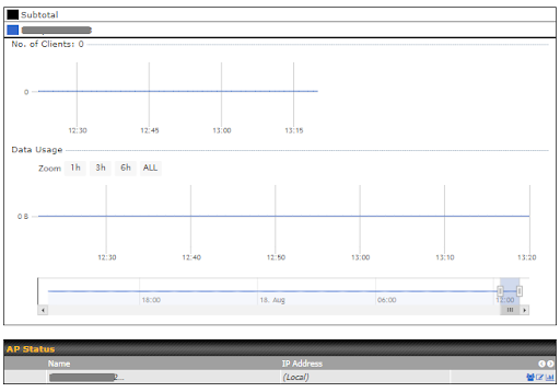
| Access Point | |
| AP Name/Serial Number | This field allows you to quickly find your device if you know its name or serial number. Fill in the field to begin searching. Partial names and serial numbers are supported. |
| AP Status | This table shows the detailed information of each AP, including channel, number of clients, upload traffic, and download traffic. On the right-hand side of the table, you will see the following icons: Clicking on the
For easier network management, you can give each client a name and designate its location. You can also designate which firmware pack (if any) that this client will follow, as well as the channels that the client will broadcast on. Clicking on the
Click on any point in the graphs to display detailed usage and client information for that device, using that SSID, at that point in time. On the Data Usage by menu, you can display the information by SSID or by AP send/receive rate. Click the Event tab next to Wireless Usage to view a detailed event log for that particular device. |
In-depth wireless SSID reports are available under AP > Wireless SSID.
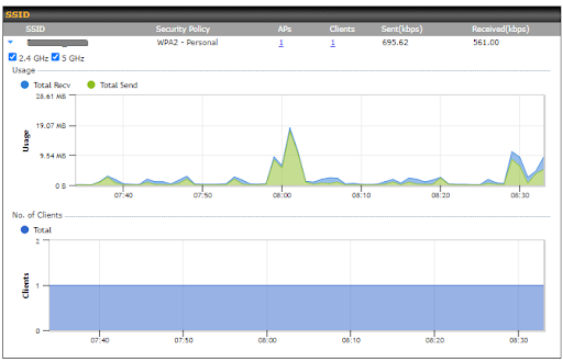
Click the blue arrow on any SSID to obtain more detailed information on usage for each SSID.
You can search for specific Wi-Fi users by navigating to AP > Wireless Client.
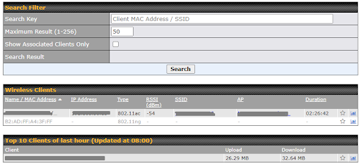
Here, you will be able to see your network’s heaviest users as well as search for specific users. Clicking on the![]() icon bookmarks the specific user, and clicking on the
icon bookmarks the specific user, and clicking on the![]() icon displays additional details about the user.
icon displays additional details about the user.
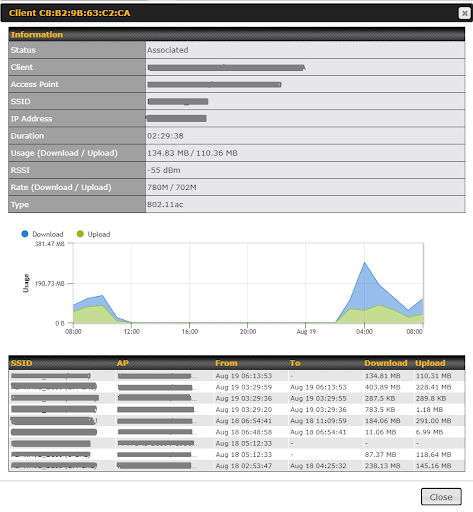
Mesh / WDS allows you to monitor the status of your wireless distribution system (WDS) or mesh network. Track activity by MAC address by navigating to AP > Mesh / WDS. This table shows the detailed information of each AP, including protocol, transmit rate (sent / received), signal strength, and duration.
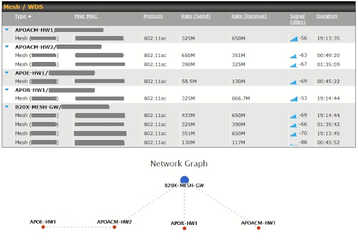
A list of nearby devices can be accessed by navigating to AP > Nearby Device.
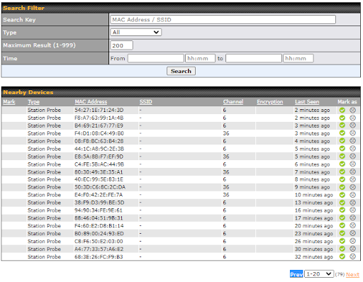
| Suspected Rogue Devices |
| Hovering over a device’s MAC address will result in a popup with information on how the device was detected. Clicking on the |
You can access the AP Controller Event log by navigating to AP > Event Log.

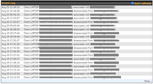
| Events |
| This event log displays all of the activity on your AP network, down to the client level. Use a filter to search for events by MAC address, SSID, AP Serial Number, or AP Profile name. Click View Alerts to see only alerts, and click the More… for additional records. |
The options on the System tab control login and security settings, firmware upgrades, SNMP settings, and other settings.
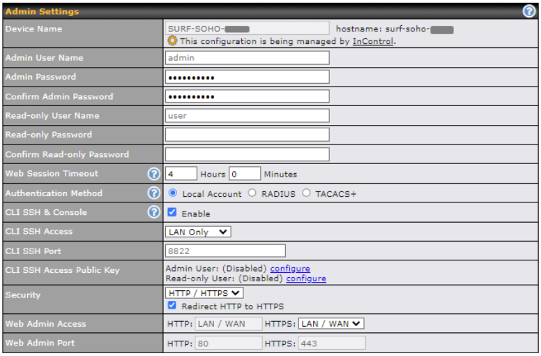
The Admin Settings section allows you to set up your access point’s name, password, security settings, and other options
| Admin Settings | |||||||||||||||||||||||
| Device Name | This field allows you to define a name for this Pepwave router. By default, Router Name is set as surf-soho-XXXX, where XXXX refers to the last 4 digits of the unit’s serial number. | ||||||||||||||||||||||
| Admin User Name | Admin User Name is set as admin by default, but can be changed, if desired. | ||||||||||||||||||||||
| Admin Password | This field allows you to specify a new administrator password. | ||||||||||||||||||||||
| Confirm Admin Password | This field allows you to verify and confirm the new administrator password. | ||||||||||||||||||||||
| Read-only User Name | Read-only User Name is set as user by default, but can be changed, if desired. | ||||||||||||||||||||||
| User Password | This field allows you to specify a new user password. Once the user password is set, the read-only user feature will be enabled. | ||||||||||||||||||||||
| Confirm User Password | This field allows you to verify and confirm the new user password. | ||||||||||||||||||||||
| Web Session Timeout | This field specifies the number of hours and minutes that a web session can remain idle before the Pepwave router terminates its access to the web admin interface. By default, it is set to 4 hours. | ||||||||||||||||||||||
| Authentication Method | With this external authentication is selected, the web admin will authenticate using the corresponding external server. Authenticated users are treated as either “admin” with full read-write permission or “user” with read-only access. Local admin and user accounts will be disabled. However, when the device is not able to communicate with the external server, local accounts are enabled to allow emergency access. By default, it is set to Local Account.
Available options:
|
||||||||||||||||||||||
| CLI SSH & Console | The CLI (command line interface) can be accessed via SSH. This field enables CLI support. For additional information regarding CLI, please refer to Section 30.5. | ||||||||||||||||||||||
| CLI SSH Access | This menu allows you to choose between granting access to LAN and WAN clients, or to LAN clients only. | ||||||||||||||||||||||
| CLI SSH Port | This field determines the port on which clients can access CLI SSH. | ||||||||||||||||||||||
| CLI SSH Access Public Key | This field is for entering the Public Key for Admin Users and Read-only Users to access CLI SSH. | ||||||||||||||||||||||
| Security | This option is for specifying the protocol(s) through which the web admin interface can be accessed:
HTTP to HTTPS redirection is enabled by default to force HTTPS access to the web admin interface. |
||||||||||||||||||||||
| Web Admin Access | This option is for specifying the network interfaces through which the web admin interface can be accessed:
If LAN/WAN is chosen, the WAN Connection Access Settings form will be displayed. |
||||||||||||||||||||||
| Web Admin Port | This field is for specifying the port number on which the web admin interface can be accessed. | ||||||||||||||||||||||
Upgrading firmware can be done in one of three ways.
Using the router’s interface to automatically check for an update, using the router’s interface to manually upgrade the firmware, or using InControl2 to push an upgrade to a router.
The automatic upgrade can be done from System > Firmware.

If an update is found the buttons will change to allow you to Download and Update the firmware.

Click on the Download and Upgrade button. A prompt will be displayed advising to download the Current Active Configuration. Please click on the underlined download text. After downloading the current config click the Ok button to start the upgrade process.
The router will download and then apply the firmware. The time that this process takes will depend on your internet connection’s speed.

The firmware will now be applied to the router*. The amount of time it takes for the firmware to upgrade will also depend on the router that’s being upgraded.

*Upgrading the firmware will cause the router to reboot.
Web admin interface : install updates manually
In some cases, a special build may be provided via a ticket or it may be found in the forum. Upgrading to the special build can be done using this method, or using IC2 if you are using that to manage your firmware upgrades. A manual upgrade using the GA firmware posted on the site may also be recommended or required for a couple of reasons.
All of the Peplink/Pepwave GA firmware can be found here Navigate to the relevant product line (ie. Balance, Max, FusionHub, SOHO, etc). Some product lines may have a dropdown that lists all of the products in that product line. Here is a screenshot from the Balance line.

If the device has more than one firmware version the current hardware revision will be required to know what firmware to download.
Navigate to System > Firmware and click the Choose File button under the Manual Firmware Upgrade section. Navigate to the location that the firmware was downloaded to select the “.img” file and click the Open button.
Click on the Manual Upgrade button to start the upgrade process.

A prompt will be displayed advising to download the Current Active Configuration. Please click on the underlined download text. After downloading the current config click the Ok button to start the upgrade process. The firmware will now be applied to the router*. The amount of time it takes for the firmware to upgrade will depend on the router that’s being upgraded.
*Upgrading the firmware will cause the router to reboot.
The InControl method
Time Settings enables the system clock of the Pepwave router to be synchronized with a specified time server. Time settings are located at System>Time.

| Time Settings | |
| Time Zone | This specifies the time zone (along with the corresponding Daylight Savings Time scheme). The Time Zone value affects the time stamps in the Pepwave router’s event log and e-mail notifications. Check Show all to show all time zone options. |
| Time Server | This setting specifies the NTP network time server to be utilized by the Pepwave router. |
Enable and disable different functions (such as WAN connections, outbound policy, and firewalls at different times, based on a user-scheduled configuration profile. The settings for this are located at System > Schedule

Enable scheduling, and then click on your schedule name or on the New Schedule button to begin.
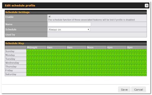
| Edit Schedule Profile | |
| Enabling | Click this checkbox to enable this schedule profile. Note that if this is disabled, then any associated features will also have their scheduling disabled. |
| Name | Enter your desired name for this particular schedule profile. |
| Schedule | Click the drop-down menu to choose pre-defined schedules as your starting point. Please note that upon selection, previous changes on the schedule map will be deleted. |
| Schedule Map | Click on the desired times to enable features at that time period. You can hold your mouse for faster entry. |
Email notification functionality provides a system administrator with up-to-date information on network status. The settings for configuring email notifications are found at System > Email Notification.
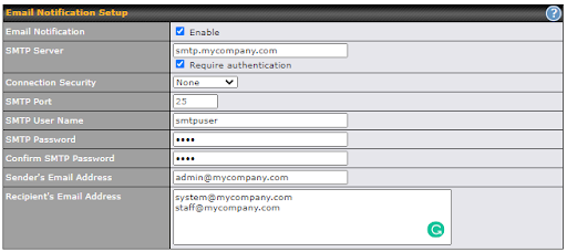
| Email Notification Setup | |
|---|---|
| Email Notification | This setting specifies whether or not to enable email notification. If Enable is checked, the Pepwave router will send email messages to system administrators when the WAN status changes or when new firmware is available. If Enable is not checked, email notification is disabled and the Pepwave router will not send email messages. |
| SMTP Server | This setting specifies the SMTP server to be used for sending email. If the server requires authentication, check Require authentication. |
| Connection Security | This setting specifies via a drop-down menu one of the following valid connection security:
When connection security is selected, SMTP Port will set a default port number automatically. |
| SMTP Port | This field is for specifying the SMTP port number. By default, this is set to 25; when STARTTLS is selected, the default port number will be set to 587. When SSL/TTS is selected, the default port number will be set to 465. You may customize the port number by editing this field. |
| SMTP User Name / Password | This setting specifies the SMTP username and password while sending email. These options are shown only if Require authentication is checked in the SMTP Server setting. |
| Confirm SMTP Password | This field allows you to verify and confirm the new administrator password. |
| Sender’s Email Address | This setting specifies the email address the Pepwave router will use to send reports. |
| Recipient’s Email Address | This setting specifies the email address(es) to which the Pepwave router will send email notifications. For multiple recipients, separate each email using the enter key. |
After you have finished setting up email notifications, you can click the Test Email Notification button to test the settings before saving. After Test Email Notification is clicked, you will see this screen to confirm the settings:

Click Send Test Notification to confirm. In a few seconds, you will see a message with detailed test results.
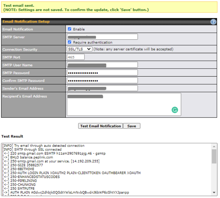
Event log functionality enables event logging at a specified remote syslog server. The settings for configuring the remote system log can be found at System>Event Log.
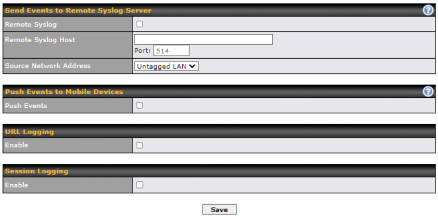
| Event Log Settings | |
| Remote Syslog | This setting specifies whether or not to log events at the specified remote syslog server. |
| Remote Syslog Host | This setting specifies the IP address or hostname of the remote syslog server and port that is used. |
| Source Network Address | Via drop-down list, you may choose the LAN interface for Event Log, URL Logging, Sessions Logging and RADIUS. |
| Push Events | The Pepwave router can also send push notifications to mobile devices that have our Mobile Router Utility installed. Check the box to activate this feature.
For more information on the Router Utility, go to: www.peplink.com/products/router-utility |
| URL Logging | This setting is to enable event logging at the specified log server. |
| URL Logging Host | This setting specifies the IP address or hostname of the URL log server. |
| Session Logging | This setting is to enable event logging at the specified log server. |
| Session Logging Host | This setting specifies the IP address or hostname of the Session log server. |
SNMP or simple network management protocol is an open standard that can be used to collect information about the Pepwave router. SNMP configuration is located at System>SNMP.
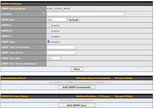
| SNMP Settings | |
| SNMP Device Name | This field shows the router name defined at System>Admin Security. |
| SNMP Port | This option specifies the port which SNMP will use. The default port is 161. |
| SNMPv1 | This option allows you to enable SNMP version 1. |
| SNMPv2 | This option allows you to enable SNMP version 2. |
| SNMPv3 | This option allows you to enable SNMP version 3. |
| SNMP Trap | This option allows you to enable SNMP Trap. If enabled, the following entry fields will appear. |
| SNMP Trap Community | This setting specifies the SNMP Trap community name. |
| SNMP Trap Server | Enter the IP address of the SNMP Trap server. |
| SNMP Trap Port | This option specifies the port which the SNMP Trap server will use. The default port is 162. |
| SNMP Trap Server Heartbeat | This option allows you to enable and configure the heartbeat interval for the SNMP Trap server. |
To add an SNMP community, click the Add SNMP Community button in the Community Name table; the following screen will be displayed:

| SNMP Community Settings | |
| Community Name | This setting specifies the SNMP community name. |
| Allowed Source Subnet Address | This setting specifies a subnet from which access to the SNMP server is allowed. Enter subnet address here (e.g., 192.168.1.0) and select the appropriate subnet mask. |
To define a username for SNMPv3, click Add SNMP User in the SNMPv3 User Name table, upon which the following screen is displayed:

| SNMPv3 User Settings | |
| User Name | This setting specifies a user name to be used in SNMPv3. |
| Authentication Protocol | This setting specifies via a drop-down menu one of the following valid authentication protocols:
When MD5 or SHA is selected, an entry field will appear for the password. |
| Privacy Protocol | This setting specifies via a drop-down menu one of the following valid privacy protocols:
When AES or DES is selected, an entry field will appear for the password. |

InControl is a cloud-based service which allows you to manage all of your Peplink and Pepwave devices with one unified system. With it, you can generate reports, gather statistics, and configure your devices automatically. All of this is now possible with InControl.
When this checkbox is checked, the device’s status information will be sent to the Peplink InControl system. This device’s usage data and configuration will be sent to the system if you enable the features in the system.
When the box Restricted to Status Reporting Only is ticked, the router will only report its status, but can’t be managed or configured by InControl.
Alternatively, you can also privately host InControl. Simply check the “Privately Host InControl” box and enter the IP Address of your InControl Host. If you have multiple hosts, you may enter the primary and backup IP addresses for the InControl Host and tick the “Fail over to InControl in the cloud” box. The device will connect to either the primary InControl Host or the secondary/backup ICA/IC2.
You can sign up for an InControl account at https://incontrol2.peplink.com/. You can register your devices under the account, monitor their status, see their usage reports, and receive offline notifications.
Backing up Pepwave router settings immediately after successful completion of initial setup is strongly recommended. The functionality to download and upload Pepwave router settings is found at System>Configuration. Note that the available options vary by model.
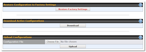
| Configuration | |
| Restore Configuration to Factory Settings | The Restore Factory Settings button is to reset the configuration to factory default settings. After clicking the button, you will need to click the Apply Changes button on the top right corner to make the settings effective. |
| Download Active Configurations | Click Download to backup the current active settings. |
| Upload Configurations | To restore or change settings based on a configuration file, click Choose File to locate the configuration file on the local computer, and then click Upload. The new settings can then be applied by clicking the Apply Changes button on the page header, or you can cancel the procedure by pressing discard on the main page of the web admin interface. |
Some Pepwave routers have features that can be activated upon purchase. Once the purchase is complete, you will receive an activation key. Enter the key in the Activation Key field, click Activate, and then click Apply Changes.

This page provides a reboot button for restarting the system. For maximum reliability, the Pepwave router can equip with two copies of firmware. Each copy can be a different version. You can select the firmware version you would like to reboot the device with. The firmware marked with (Running) is the current system boot up firmware.
Please note that a firmware upgrade will always replace the inactive firmware partition.

The ping test tool sends pings through a specific Ethernet interface or a SpeedFusion™ VPN connection. You can specify the number of pings in the field Number of times, to a maximum number of 10 times. Packet Size can be set to a maximum of 1472 bytes. The ping utility is located at System > Tools > Ping, illustrated below:
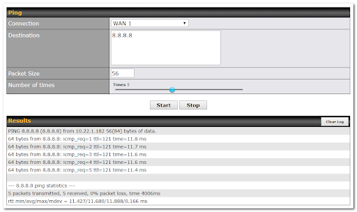
| Tip |
| A system administrator can use the ping utility to manually check the connectivity of a particular LAN/WAN connection. |
The traceroute test tool traces the routing path to the destination through a particular Ethernet interface. The traceroute test utility is located at System > Tools > Traceroute.
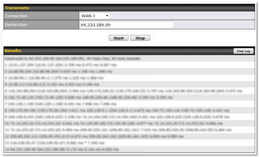
| Tip |
| A system administrator can use the traceroute utility to analyze the connection path of a LAN/WAN connection. |
Peplink routers can send special “magic packets” to any client specified from the Web UI. To access this feature, navigate to System > Tools > Wake-on-LAN.

Select a client from the drop-down list and click Send to send a “magic packet”
The WAN Analysis feature allows you to run a WAN to WAN speed test between 2 Peplink devices .
You can set a device up as a Server or a Client. One device must be set up as a server to run the speed tests and the server must have a public IP address.
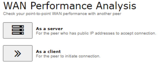
The default port is 6000 and can be changed if required. The IP address of the WAN interface will be shown in the WAN Connection Status section.
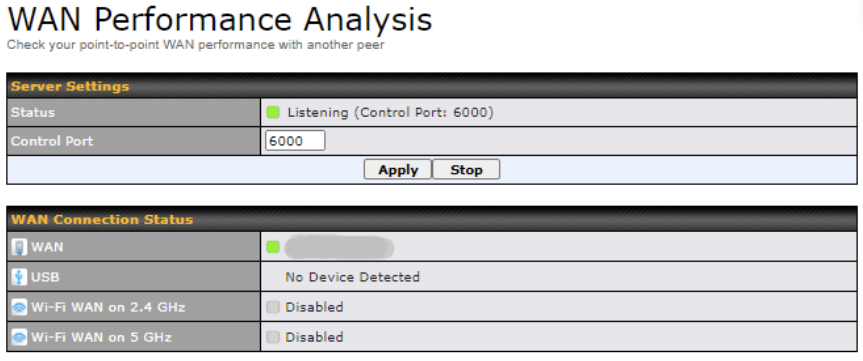
The client side has a few more settings that can be changed. Make sure that the Control Port matches what’s been entered on the server side. Select the WAN(s) that will be used for testing and enter the Servers WAN IP address. Once all of the options have been set, click the Start Test button.
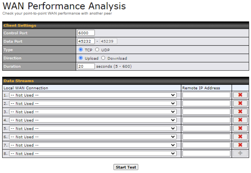
The test output will show the Data Streams Parameters, the Throughput as a graph, and the Results.
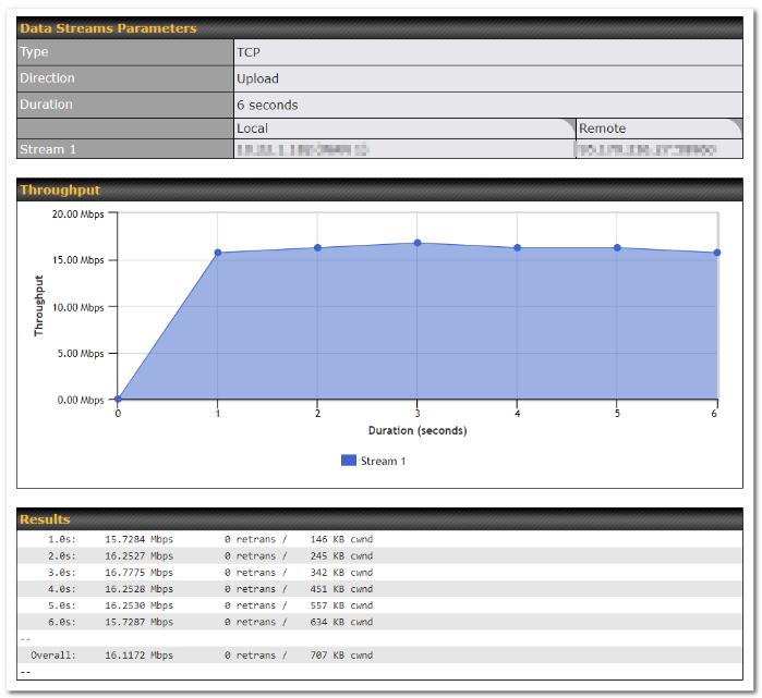
The test can be run again once it’s complete by clicking the Start button or you can click Close and change the parameters for the test.
System information is located at Status > Device.
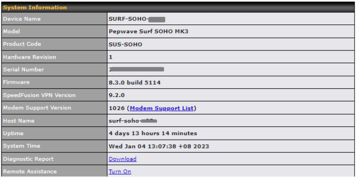
| System Information | |
| Device Name | This is the name specified in the Device Name field located at System > Admin Security. |
| Model | This shows the model name and number of this device. |
| Product Code | If your model uses a product code, it will appear here. |
| Hardware Revision | This shows the hardware version of this device. |
| Serial Number | This shows the serial number of this device. |
| Firmware | This shows the firmware version this device is currently running. |
| SpeedFusion VPN Version | This shows the current PepVPN version. |
| Modem Support Version | This shows the modem support version. For a list of supported modems, click Modem Support List. |
| InControl Managed Configurations | If the router is (partly) managed by InControl, the options controlled by InControl are listed in this field. |
| Host Name | The host name assigned to the Pepwave router appears here. |
| Uptime | This shows the length of time since the device has been rebooted. |
| System Time | This shows the current system time. |
| Diagnostic Report | The Download link is for exporting a diagnostic report file required for system investigation. |
| Remote Assistance | This option is to Turn on remote assistance with the time duration. |

The second table shows the MAC address of each LAN/WAN interface connected. To view your device’s
End User License Agreement (EULA), follow the Legal link
| Important Note |
| If you encounter issues and would like to contact the Pepwave Support Team, please download the diagnostic report file and attach it along with a description of your issue. |
Information on active sessions can be found at Status>Active Sessions>Overview.
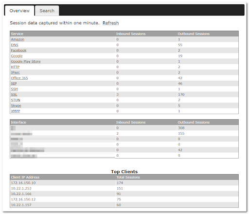
This screen displays the number of sessions initiated by each application. Click on each service listing for additional information. This screen also indicates the number of sessions initiated by each WAN port. In addition, you can see which clients are initiating the most sessions.
You can also perform a filtered search for specific sessions. You can filter by subnet, port, protocol, and interface.
To perform a search, navigate to Status > Active Sessions > Search.
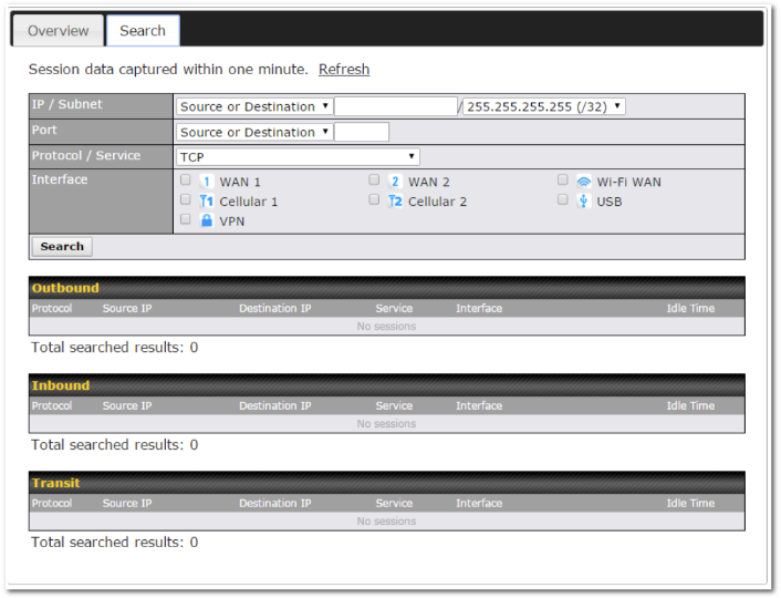
This Active Sessions section displays the active inbound/outbound sessions of each WAN connection on the Pepwave router. A filter is available to sort active session information. Enter a keyword in the field or check one of the WAN connection boxes for filtering.
The client list table is located at Status > Client List. It lists DHCP and online client IP addresses, names (retrieved from the DHCP reservation table or defined by users), current download and upload rate, and MAC address. Clients can be imported into the DHCP reservation table by clicking the ![]() button on the right. You can update the record after import by going to Network > LAN.
button on the right. You can update the record after import by going to Network > LAN.
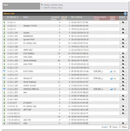

Information on OSPF and RIPv2 can be found in this section.

Information on BGP can be found in this section.
PepVPN Status shows the current connection status of each connection profile and is displayed at Status> PepVPN/SpeedFusion.

Click on the corresponding peer name to explore the WAN connection(s) status and subnet information of each VPN peer.

Click button for a chart displaying real-time throughput, latency, and drop-rate information for each WAN connection.
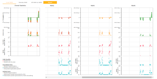
When pressing the ![]() button the following menu will appear:
button the following menu will appear:
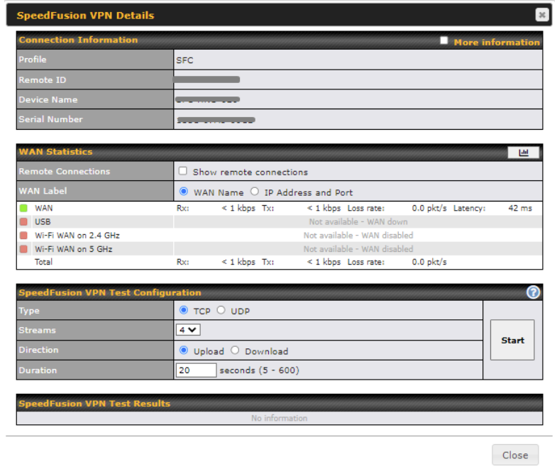
The Speedfusion status page shows all related information about the PepVPN connection.
This screen also allows you to run PepVPN Tests allowing throughput tests.
Peplink also published a whitepaper about Speedfusion which can be downloaded from the following url:
http://download.peplink.com/resources/whitepaper-speedfusion-and-best-practices-2019.pdf
Event log information is located at Status > Event Log
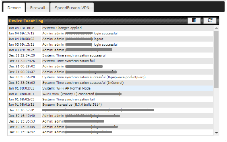
The log section displays a list of events that has taken place on the Pepwave router. Check Auto Refresh to refresh log entries automatically. Click the Clear Log button to clear the log.
WAN Quality allows you to select each WAN and view current WAN Quality.
Detailed information can be seen when selecting a point on the graph.
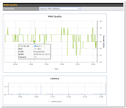
This section shows bandwidth usage statistics and is located at Status>Bandwidth. Bandwidth usage at the LAN while the device is switched off (e.g., LAN bypass) is neither recorded nor shown.
Real Time
The Data transferred since installation table indicates how much network traffic has been processed by the device since the first bootup. The Data transferred since last reboot table indicates how much network traffic has been processed by the device since the last boot up.
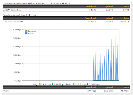
Hourly
This page shows the hourly bandwidth usage for all WAN connections, with the option of viewing each individual connection. Select the desired connection to check from the drop-down menu.
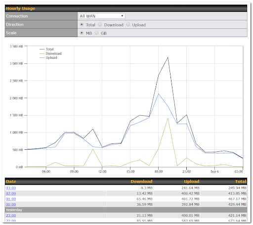
Daily
This page shows the daily bandwidth usage for all WAN connections, with the option of viewing each individual connection.
Select the connection to check from the drop-down menu. If you have enabled the Bandwidth Monitoring feature, the Current Billing Cycle table for that WAN connection will be displayed.
Click on a date to view the client bandwidth usage of that specific date. This feature is not available if you have selected to view the bandwidth usage of only a particular WAN connection. The scale of the graph can be set to display megabytes (MB) or gigabytes (GB).
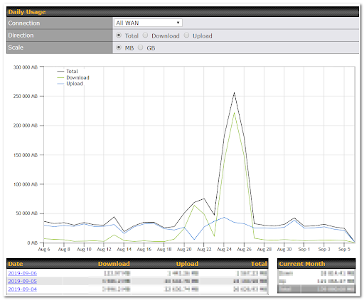
Monthly
This page shows the monthly bandwidth usage for each WAN connection. If you have enabled the Bandwidth Monitoring feature, you can check the usage of each particular connection and view the information by Billing Cycle or by Calendar Month.
Click the first two rows to view the client bandwidth usage in the last two months. This feature is not available if you have chosen to view the bandwidth of an individual WAN connection. The scale of the graph can be set to display megabytes (MB) or gigabytes (GB).
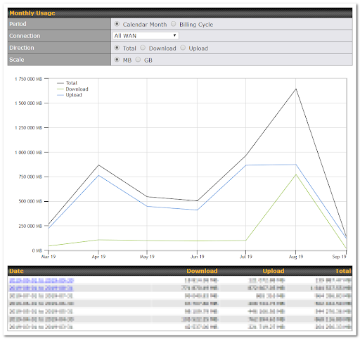
To restore the factory default settings on your Pepwave Surf SOHO unit, follow the steps below:
Hold for approximately 10 seconds for factory reset (Note: The LED status light shows in RED, until the status light off and release the button).
After the Pepwave Surf SOHO finishes rebooting, the factory default settings will be restored.
| Important Note |
| All previous configurations and bandwidth usage data will be lost after restoring factory default settings. Regular backup of configuration settings is strongly recommended. |
| Default Port Number | Usage | Service | Inbound/Outbound | Default Status |
| UDP 5246 | Data flow | InControl | Outbound | Enabled |
| TCP 443 | HTTPS service | InControl | Outbound | Enabled |
| TCP 5246 | Optional, used when TCP 443 is not responding | InControl | Outbound | Enabled |
| TCP 5246 | Remote Web Admin | InControl Virtual Appliance | Outbound | Enabled |
| TCP 4500 | VPN Data (TCP Mode) | PepVPN / SpeedFusion | Inbound / Outbound* | Disabled |
| TCP 32015 | VPN handshake | PepVPN / SpeedFusion | Inbound / Outbound* | Disabled |
| UDP 4500 | VPN Data | PepVPN / SpeedFusion | Inbound / Outbound* | Disabled |
| UDP 32015º | VPN Data (alternative) | PepVPN / SpeedFusion | Inbound / Outbound* | Disabled |
| TCP/UDP 4500+N-1^ | VPN Sub-Tunnels Data | PepVPN / SpeedFusion | Inbound / Outbound* | Disabled |
| UDP 32015+N-1^ | VPN Sub-Tunnels Data (alternative) | PepVPN / SpeedFusion | Inbound / Outbound* | Disabled |
| UDP 4500 | VPN Data | IPsec | Inbound / Outbound* | Disabled |
| UDP 500 | VPN initiation | IPsec | Inbound / Outbound* | Disabled |
| UDP 500 | L2TP | Remote User Access | Inbound | Disabled |
| UDP 1701 | L2TP | Remote User Access | Inbound | Disabled |
| UDP 4500 | L2TP | Remote User Access | Inbound | Disabled |
| UDP 1194 | OpenVPN | Remote User Access | Inbound | Disabled |
| IP 47 | PPTP (GRE) | Remote User Access | Inbound | Disabled |
| TCP 2222 | Remote Assistance Direct connection | Peplink Troubleshooting Assistance | Outbound | Enabled |
| TCP 80 | HTTP traffic | Web Admin Interface access | Inbound | Enabled |
| TCP 443 | HTTPS traffic | Web Admin Interface access (secure) | Inbound | Enabled |
| TCP 8822 | SSH | SSH | Inbound | Disabled |
| UDP 161 | SNMP Get | SNMP monitoring | Inbound | Disabled |
| UDP 162 | SNMP Trap | SNMP monitoring | Outbound | Disabled |
| TCP, UDP 1812 | Radius Authentication | Radius | Outbound | Disabled |
| TCP, UDP 1813 | Radius Accounting | Radius | Outbound | Disabled |
| UDP 123 | Network Time Protocol | NTP | Inbound
Outbound |
Disabled
Enabled |
| TCP 60660 | Real-time location data in NMEA format | GPS | Outbound | Disabled |
Disclaimer:
The default UDP data ports used when using (N number of Sub-Tunnel profiles) are: 4500…4500+N-1, or (when port 4500 is in use by IPsec or L2TP/IPsec) 32015… 32015+N-1″.
Ethernet Cables
We recommend that you use a shielded cable to connect the Ethernet ports for the network.
This device complies with Part 15 of the FCC Rules. Operation is subject to the following two conditions: (1) This device may not cause harmful interference, and (2) this device must accept any interference received, including interference that may cause undesired operation.
This equipment has been tested and found to comply with the limits for a Class B digital device, pursuant to Part 15 of the FCC Rules. These limits are designed to provide reasonable protection against harmful interference in a residential installation. This equipment generates, uses and can radiate radio frequency energy and, if not installed and used in accordance with the instructions, may cause harmful interference to radio communications. However, there is no guarantee that interference will not occur in a particular installation. If this equipment does cause harmful interference to radio or television reception, which can be determined by turning the equipment off and on, the user is encouraged to try to correct the interference by one of the following measures:
-Reorient or relocate the receiving antenna.
-Increase the separation between the equipment and receiver.
-Connect the equipment into an outlet on a circuit different from that to which the receiver is connected.
-Consult the dealer or an experienced radio/TV technician for help.
Any changes or modifications not expressly approved by the party responsible for compliance could void the user’s authority to operate this equipment.
Operations in the 5.15-5.25GHz band are restricted to indoor usage only.
Radiation Exposure Statement
This equipment complies with FCC RF radiation exposure limits set forth for an uncontrolled environment. This equipment should be installed and operated with a minimum distance of 20 cm between the radiator and your body.
The availability of some specific channels and/or operational frequency bands are country dependent and are firmware programmed at the factory to match the intended destination.

2.4GHz ( 2412 – 2472 MHz ) : 19.88 dBm
5GHz ( 5150 – 5250 MHz ) : 22.57 dBm
This equipment complies with CE radiation exposure limits set forth for an uncontrolled envi- ronment. This equipment should be installed and operated with a minimum distance of 20cm between the radiator & your body.
This equipment is restricted to indoor use only when operating in the 5150 to 5250 MHz frequency range in above countries.
contact as: https://www.peplink.com/
USB WAN Modem Port Specification
Surf SOHO Series
| Surf SOHO | |
| Output Rating | 5V DC, 2A |